


- Effect of La2O3 on the microstructure and electrical properties of ZnO linear resistors
Yajun Fu#, Jiajia Lu#, Jin Wang and Liangfeng Li*
School of Materials and Chemistry, Southwest University of Science and Technology, Mianyang 621010, China
This article is an open access article distributed under the terms of the Creative Commons Attribution Non-Commercial License (http://creativecommons.org/licenses/by-nc/4.0) which permits unrestricted non-commercial use, distribution, and reproduction in any medium, provided the original work is properly cited.
ZnO-MgO-Al2O3-TiO2-Y2O3 linear resistors with different amount of La2O3 were successfully prepared by the conventional solid-state sintering method. The crystalline phase composition, microstructure, and electrical properties of La2O3 doped ZnO linear resistors were investigated. The results show that La2O3 influences the lattice of ZnO and generates La-rich phase at the grain boundaries, which improves the dense density of ZnO linear resistors. The addition of La2O3 further affect the electrical properties of ZnO linear resistors, such as the temperature stability. The sample with 0.5 wt.% La2O3 show excellent electrical performance with an resistance-temperature coefficient of 0.21×10⁻³/°C and an nonlinear coefficient of 1.05
Keywords: ZnO linear resistor, La2O3, Microstructure, Electrical properties
As an n-type semiconductor with a wide bandgap of 3.37 eV, ZnO has been widely used in solar cells [1-3], sensors [4-6], high frequency devices [7-9], photocatalysis [10-12], varistors [13-15], linear resistors [16-18] and so on. ZnO linear resistor, which has low resistance-temperature coefficient and small nonlinear coefficient, is a kind of composite resistance material with ZnO as the host material and oxides such as MgO, Al2O3, TiO2, and SiO2 as the additives [17-22]. Compared with traditional metal and carbon based resistors, ZnO linear resistors have large flow density, adjustable resistivity, better stability, and excellent resistance-temperature characteristic [22-24]. Therefore, ZnO linear resistors have been widely used in high energy areas such as neutral grounding resistors and circuit breakers [16].
The addition of oxides is one of the most efficient way to improve the performance of ZnO linear resistances. Fe2O3 can be used as a donor dopant to reduce the barrier height of the grain boundary and improve the linear current-voltage (I-V) characteristic of ZnO linear resistors [21]. The addition of NiO into ZnO linear resistors improves the microstructure uniformity, energy density, and resistance-temperature characteristic [25]. CaO doping can limit the grain size of ZnO linear resistors, and then improve the electrical properties, including decrease the grain boundary barrier height and nonlinear coefficient, as well as optimize the resistance-temperature coefficient [26]. The doping of Sc2O3 enhances the linear characteristics of ZnO linear resistor, and further affects its dielectric properties [17].
In addition to the type of the doped oxides, the reactions of the doped oxides and ZnO also influence the performance of ZnO linear resistors [20, 27, 28]. The added oxides react with ZnO to produce spinel during the sintering process, which can modulate the resistance of the linear resistor and improve its resistance-temperature characteristic [22, 23]. As a rare earth oxide, La2O3 may react with ZnO, that is, the La3+ plays a donor dopant to substitute Zn2+ in the ZnO grains and create lattice defects [29]. On the other hand, the addition of La2O3 is likely to lead to La-rich phase in the ZnO linear resistors. Thus, the barrier height at the grain boundary and the resistance characteristic of ZnO linear resistor may be modulated by the doping amount of La2O3. Recent report on La2O3 doped ZnO linear resistors indicates that La2O3 doping can promote the performance of ZnO linear resistors and could enables its application in high-frequency electric field [22]. Further investigating the effect of La2O3 doping on ZnO linear resistors helps to better understand the mecha nism of the promoted electrical performance and further modulate its electrical properties. In our work, ZnO-MgO-Al2O3-TiO2-Y2O3 linear resistors with different addition amounts of La2O3 were prepared via conventional solid-state sintering method. We studied the phase composition and microstructure of the ZnO linear resistors, and analysed the mechanism of the effect of La2O3 on the electrical properties of ZnO linear resistors.
ZnO linear resistors were fabricated through conventional solid-state sintering method with analytical grade raw materials. The mass compositions was (86.684-x) wt.% ZnO+7 wt.% Al2O3+5 wt.% MgO+0.6 wt.% TiO2+0.716 wt.%Y2O3+x wt.% La2O3 (x = 0, 0.25, 0.5, 0.75 or 1). The raw materials were mixed with deionized water in a planetary ball mill at a speed of 356 r/min for 24 h. The mass ratio of powders, water, and zirconia balls was 1:3:3. The resulting slurry was dried at 100 ℃ for 24 h in an air dry oven. The obtained dry mixture was crashed into powders and prilled with 8 wt.% PVA, followed by aging for 24 h. The prilled powders were pressed into discs with 20 mm in diameter and 3 mm in thickness under the pressure of 10 MPa, and then the discs were sintered for 3 h at 1360 ℃. Finally, after a cooling procedure (2 ℃/min), the specimens were polished and coated with aluminum electrodes for further electric measurement.
The microstructure of the as-prepared specimens was observed by a scanning electron microscope (Hitachi desktop TM - 4000, Japan), and the grain size was calculated based on the linear intercept method [30]. The elemental distribution of the specimens were determined by an energy dispersive spectrometer (EDS). The crystalline phase and lattice constants of the specimens were characterized by an X-ray diffractometer (XRD, DMAX1400, Japanese physics) using Cu Kα radiation (λ = 0.154 nm).
The I-V curves of ZnO linear resistors at 0-4 V were measured by HRMS-800 high temperature insulating material resistivity measurement system. The nonlinear coefficient of was calculated by the following equation [31]:

where U1 and U2 are the voltage values at two different points of an I-V curve, I1 and I2 are the current values at the voltage of U1 and U2 respectively. In this paper, the obtained α is averaged over 10 data points. The resistance-temperature (R-T) curves of ZnO linear resistors in the temperature range of 25-300 ℃ were tested by HRMS-900 high temperature insulating material resistivity measurement system. The resistance-temperature coefficient is calculated by the following equation [32]:
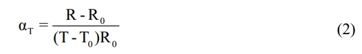
where T0 is the initial temperature of the test (25 ℃), R0 is the resistance of the sample at 25 °C, R is the resistance of the sample at temperature T. The calculation is averaged over 10 data points.
XRD characterization
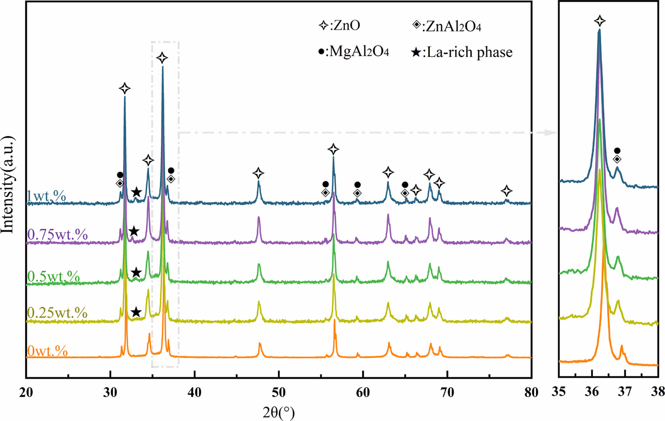
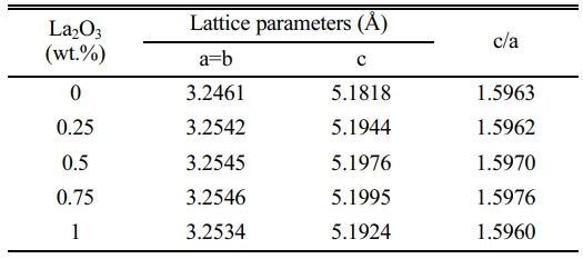
Fig. 1 shows XRD patterns of the ZnO linear resistors with different amounts of La2O3 additive. The main crystalline phase compositions of the ZnO linear resistors without La2O3 are ZnO, ZnAl2O4, and MgAl2O4. After the addition of La2O3, a diffraction peak with a low intensity appears at 32°-33°, and its intensity increases with the increase of La2O3 addition. The phase corresponding to this diffraction peak is La-rich phase [22, 33]. The enlarged XRD patterns in the range of 35-38° shows that the addition of La2O3 leads to a leftward shift (towards the small diffraction angle) of the diffraction peak of ZnO, which means the increase of lattice parameters. This is due to the replacement of Zn2+ (74 pm) by La3+ (106 pm) during sintering. With the increase of La2O3 addition, the lattice parameters of ZnO increase first and then decrease, as shown in Table 1. When the addition of La2O3 is 0.75 wt.%, the lattice parameters of ZnO reach the maximum. Further increasing La2O3 to 1 wt.% decreases the lattice parameters of ZnO. This may be due to the fact that when too much La2O3 is added, it is more likely to segregate at the grain boundaries and resulting in less La3+ entering the ZnO lattice.
Bulk density
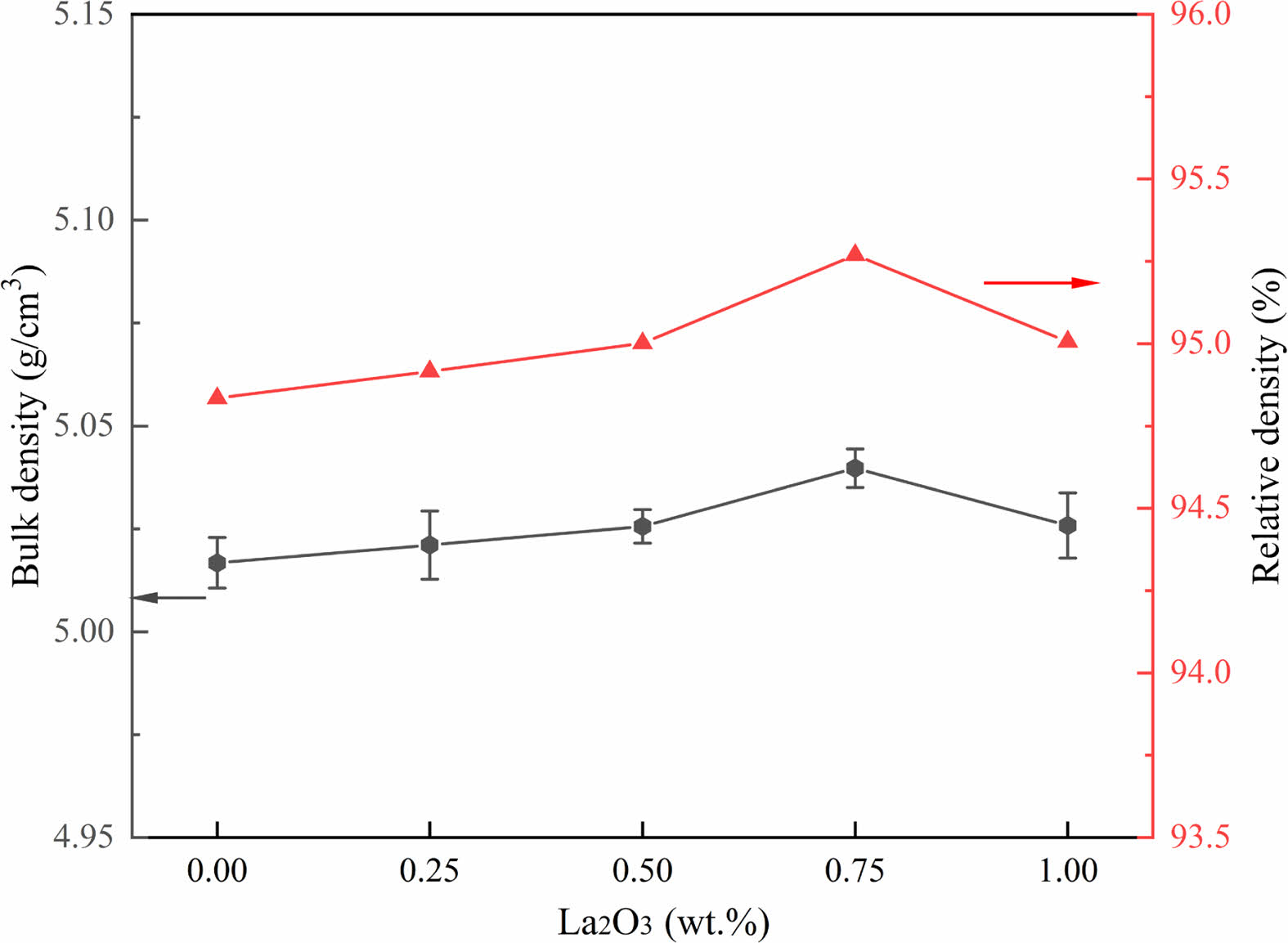
The bulk density and relative density of the samples with different different amounts of La2O3 are shown in Fig. 2. The density of the samples increases with the increase of La2O3 addition, and slightly decreases when the addition of La2O3 is greater than 0.75 wt.%. When the addition of La2O3 is 0.75 wt.%, the bulk density and relative density of the ZnO linear resistors are 5.040 g/cm3 and 95.27% respectively, which are the maximum values of these samples. The slightly increased density of the samples with the addition of La2O3 is because La2O3 has the effect of activating the lattice [22]. However, when the La2O3 addition is 1 wt.%, the segregation of the La-rich phase at the grain boundaries affects the homogeneity of ZnO [29] and cause the decrease of density.
Microstructure characterization
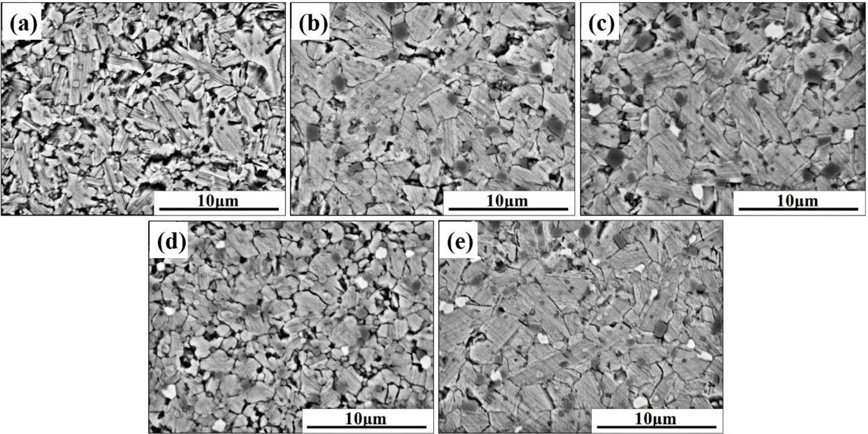
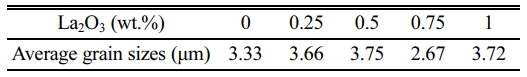
To understand the impact of the La2O3 on the microstructure, we observed the morphology of the samples with different amounts of La2O3 by SEM, as shown in Fig. 3. Without the addition of La2O3, the ZnO grains are irregularly slender in shape. With the increase of La2O3 addition, a new phase (bright areas in Fig. 3(c-e)) appeared, which may be La-rich phase that manifested in XRD patterns. Moreover, the ZnO grain size increases with the increase of La2O3 addition except the sample with La2O3 addition of 0.75 wt.% (as summarized in Table 2). When the addition of La2O3 is 0.75 wt.%, the ZnO grain size is significantly refined and uniformly distributed.
During the sintering process, atoms diffuse along the grain boundaries, causing migration of grain boundaries and growth of grains [34, 35]. The migration of grain boundaries is determined by the distribution of the second phase at the grain boundaries and the defects in other regions. The effect of La2O3 on the microstructure of ZnO linear resistors is mainly manifested in two ways: (1) La3+ distributes at the grain boundaries and activates the migration of grain boundaries, leading to the growth of ZnO grains; (2) La3+ enters the lattice of ZnO by substituting Zn2+ [29], which inhibit the migration of grain boundaries and the growth of grains. When the amount of La2O3 is small, La3+ ions mainly distribute at the grain boundaries, which results in the increase of grain size. However, with the increase of La2O3, more La3+ ions enter the lattice of ZnO and inhibit the growth of grains.
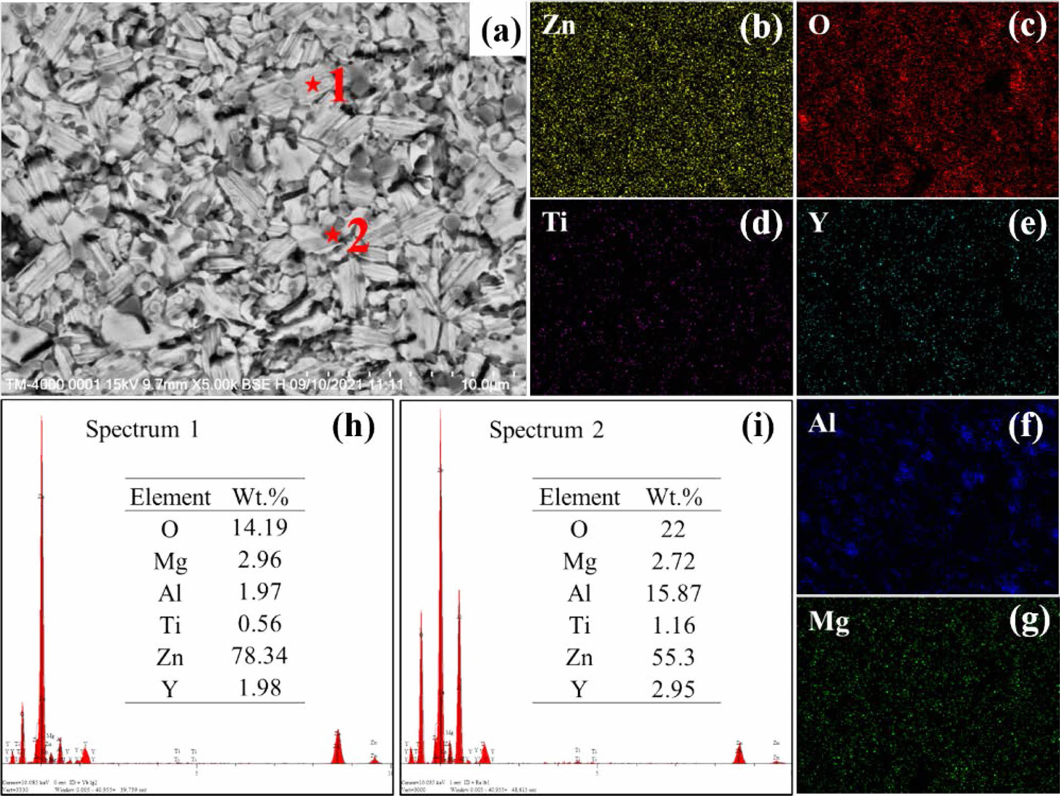
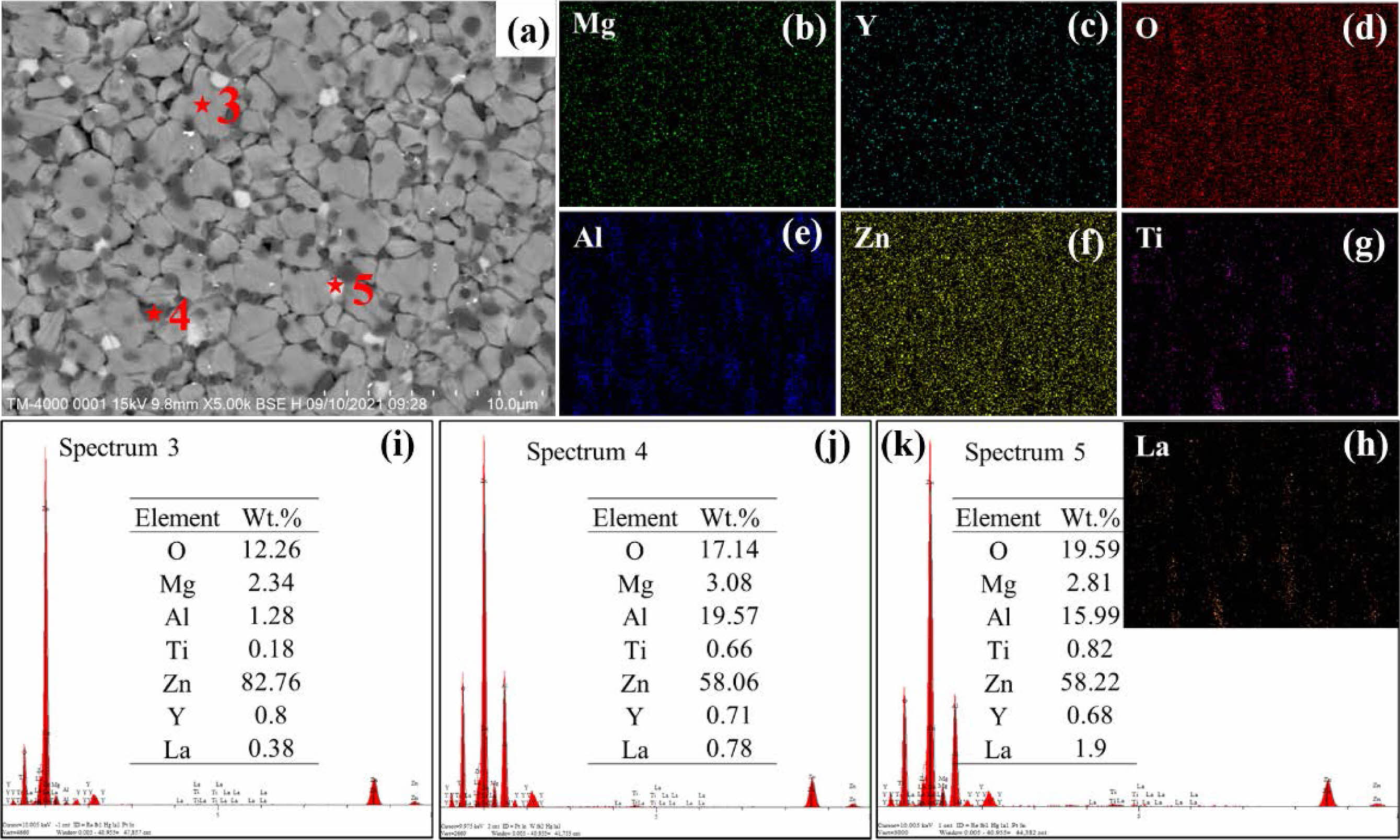
To further determine the phase composition of the ZnO linear resistors, we performed EDS measurements. Fig. 4 and Fig. 5 show the EDS results of ZnO linear resistors without and with 0.75 wt.% La2O3, respectively. According to the element mappings and element ratios results, the sample without addition of La2O3 is mainly composed of ZnO (light grey areas) and spinel phase (dark grey areas). In the sample with 0.75 wt.% La2O3, La element is mainly distributed at the grain boundaries and formed the La-rich phase (bright areas). In addition, the aggregation of Ti element at the grain boundaries in the sample with 0.75 wt.% La2O3 is significantly enhanced compared with the sample without addition of La2O3. Ti element can enter the ZnO lattice and promote the growth of grain [16]. The aggregation of Ti element at the grain boundaries indicate that there is less Ti in ZnO lattice, which may be a reason that cause the refinement of ZnO grains in the sample with 0.75 wt.% La2O3.
Electrical properties
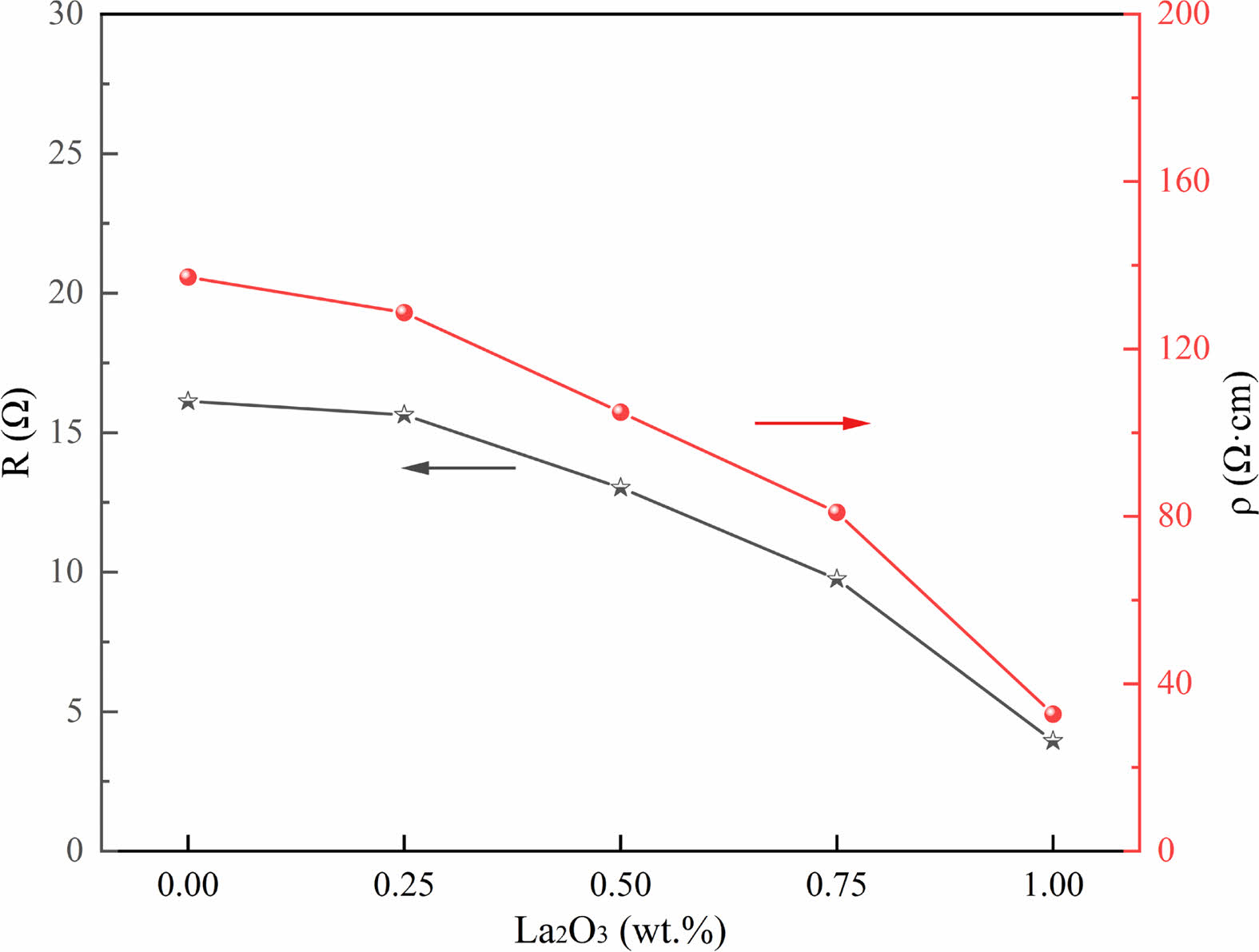
It is critical to know the electrical properties of La2O3 doped ZnO linear resistors, such as the resistivity, resistance-temperature coefficient, and nonlinear coefficient of the samples. Fig. 6 shows the resistance and resistivity of ZnO linear resistors with different amounts of La2O3. The resistance and resistivity of ZnO linear resistors decrease significantly with the increase of La2O3. The resistance (resistivity) values of the sample without addition of La2O3 is 16.12 Ω (137.18 Ω·cm), and the resistance (resistivity) values of the sample with 1 wt.% La2O3 is decreased to 3.95 Ω (32.76 Ω·cm). The resistance of ZnO linear resistors is determined by both the low resistance ZnO grain and the high resistance grain boundary phase. The addition of La2O3 not only affects the grain boundaries, but also reduces the resistance of ZnO grains because La3+ enter the lattice of ZnO can increase the concentration of free electrons [29]. As a result, the resistance and resistivity of ZnO linear resistors decreases with the addition of La2O3.
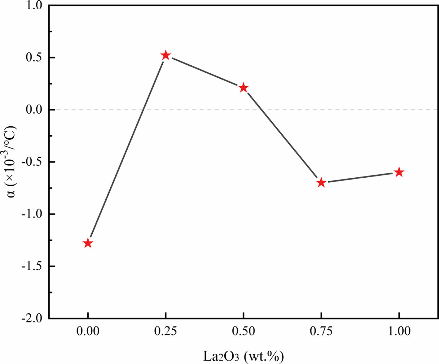
The resistance-temperature coefficients of the ZnO linear resistors are shown in Fig. 7. The absolute values of the ZnO linear resistors with different amounts of La2O3 were reduced to smaller than 10-3/°C, which indicate that the addition of La2O3 improves the temperature stability of the ZnO linear resistors noticeably. When the addition of La2O3 is 0.5 wt.%, the sample has the best temperature stable performance with a resistance-temperature coefficient of 0.21 × 10⁻³/°C. The improvement of the temperature stable performance of ZnO linear resistors is because the added La2O3 influenced the grain boundaries and promoted the conductance of ZnO.
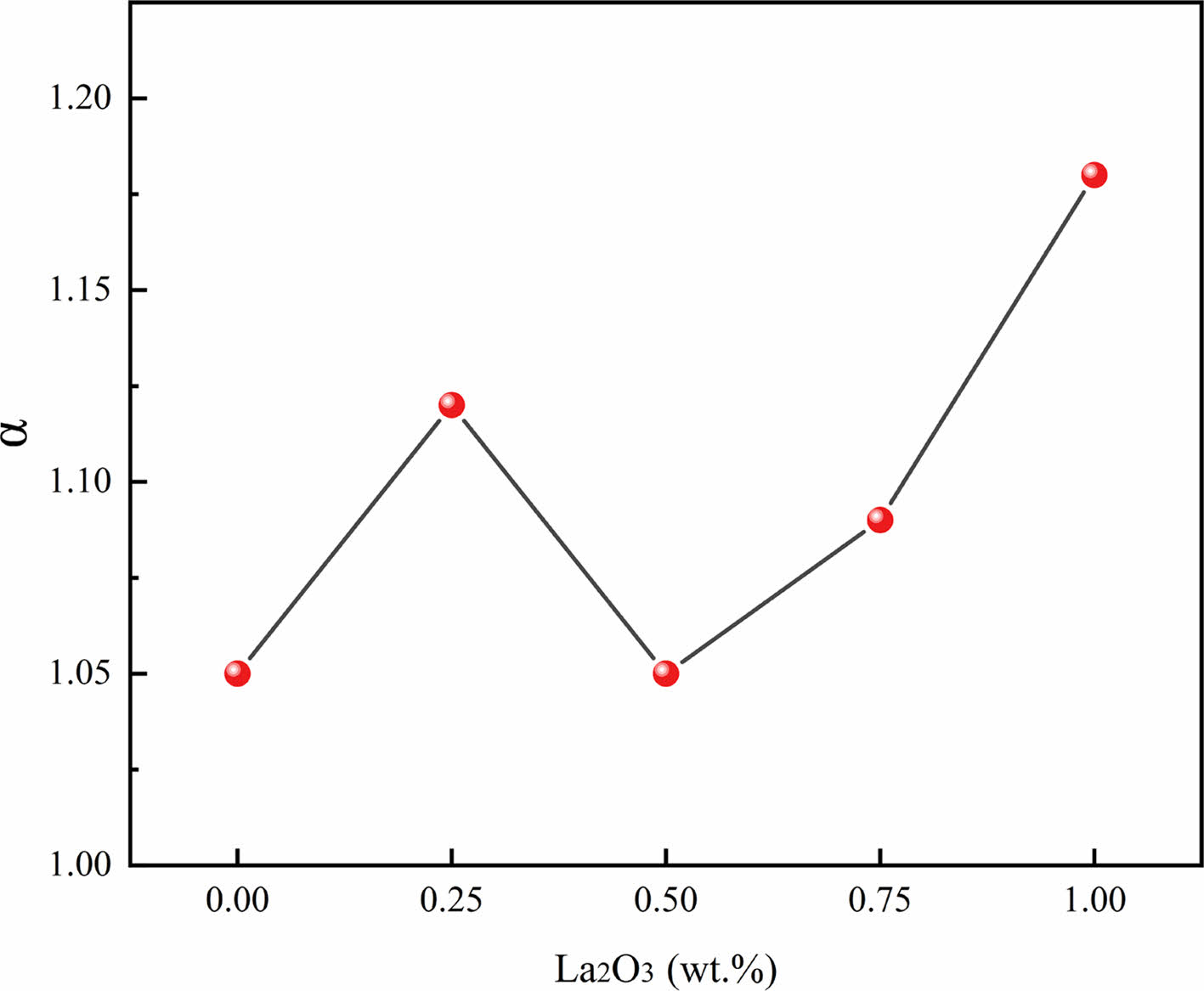
Fig. 8 shows the nonlinear coefficient of ZnO linear resistors with different amounts of La2O3. The addition of La2O3 increases the nonlinear coefficient of the samples except the sample with 0.5 wt.% La2O3. We further analysed the temperature dependent resistivity according to the thermally activated conduction mechanism because the electrical transport in semiconductor ceramics is thermally activated. The resistivity of ZnO linear resistors can be expressed as [17, 22]

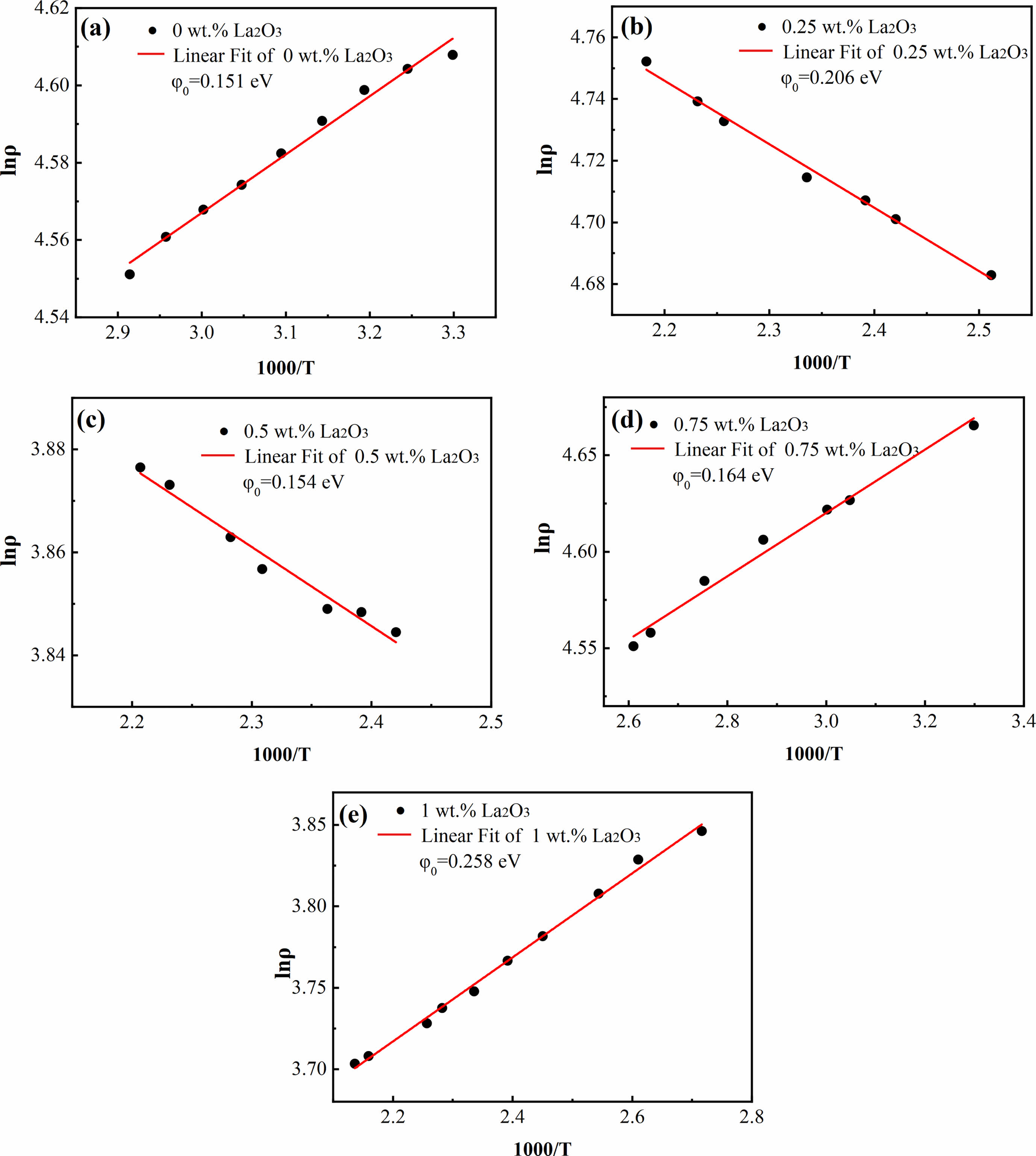
where ρ is the resistivity of the sample, ρ0 is the resistivity of the sample as the temperature tends to infinity; φ0 is the height of the grain boundary potential barrier (equal to value of the activation energy), k is the Boltzmann constant, and T is the absolute temperature. The Arrhenius plots of the temperature dependent resistivity of ZnO linear resistors are shown in Fig. 9. We linearly fitted the relationship between lnρ and 1000/T and obtained the height of the grain boundary potential barrier by calculating the slops. Here, all the coefficient of determination (R2) are greater than 0.98, indicating that the electrical transport in ZnO linear resistors matches the thermally activated conduction mechanism well. The addition of La2O3 increases φ0 obviously except the sample with 0.5 wt.% La2O3, which is consistent with the trend of nonlinear coefficient. This indicate that the nonlinearly electrical characteristic of La2O3 doped ZnO linear resistors is determined by the grain boundary potential barrier, which is adjusted by the addition of La2O3.
The potential barrier height φ0 is expressed by the following equation [17, 22]:
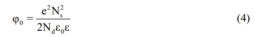
where e is the elementary charge, NS is the density of interfacial state, Nd is the donor density, ε is relative dielectric constant, and ε0 is the vacuum dielectric constant. When La2O3 is added into ZnO linear resistors, some of the La3+ ions enter ZnO lattice to increase the donor density Nd and decrease φ0; the other La3+ ions distribute at the grain boundaries to generate La-rich phase, which increase the density of interfacial state NS and thus increase φ0. Because ionic radius of La3+ (106 pm) is much greater than that of Zn2+ (74 pm), the amount of La3+ ions that entering ZnO lattice is limited and most of the La3+ ions are distribute at the grain boundaries to generate La-rich phase. As a result, the height of the grain boundary potential barrier is increased and the nonlinearity of the I-V curves also increased.
Due to the complicated components of La2O3 doped ZnO linear resistors, all the main crystalline phases, including ZnO, spinel phase, and La-rich phase, can affect the grain boundary potential barrier and charge transport, which makes the factors that affect their electrical conductance quite complex. Thus, more researches are needed in the future to better understand the resistance-temperature characteristic and I-V characteristic.
|
Fig. 1 XRD patterns of the ZnO linear resistors with different amount of La2O3. |
|
Fig. 2 The bulk density and relative density of ZnO linear resistors with different amount of La2O3. |
|
Fig. 3 SEM images of ZnO linear resistors with different amount of La2O3. (a) without La2O3, (b) 0.25 wt.% La2O3, (c) 0.5 wt.% La2O3, (d) 0.75 wt.% La2O3, and (e) 1 wt.% La2O3. |
|
Fig. 4 EDS characterization of ZnO linear resistor without addition of La2O3. (a) SEM image, (b)-(g) element mappings of Zn, O, Ti, Y, Al, and Mg. (h) and (i) show the energy dispersive spectra of the ZnO grain (position 1) and spinel phase (position 2), respectively. |
|
Fig. 5 EDS characterization of ZnO linear resistor with 0.75 wt.% La2O3. (a) SEM image, (b)-(h) element mappings of Mg, Y, O, Al, Zn, Ti, and La. (i)-(k) show the energy dispersive spectra of the ZnO grain (position 3), spinel phase (position 4), and La-rich phase (position 5), respectively. |
|
Fig. 6 Resistance and resistivity of ZnO linear resistors with different amount of La2O3. |
|
Fig. 7 Resistance-temperature coefficient of ZnO linear resistors with different amount of La2O3. |
|
Fig. 8 Nonlinear coefficient of ZnO linear resistors with different amount of La2O3. |
|
Fig. 9 Arrehenius plots of the temperature dependent resistivity of ZnO linear resistors with different amount of La2O3. (a) without La2O3, (b) 0.25 wt.% La2O3, (c) 0.5 wt.% La2O3, (d) 0.75 wt.% La2O3, and (e) 1 wt.% La2O3. |
|
Table 1 Lattice parameters of ZnO in ZnO linear resistors added different amounts of La2O3. |
|
Table 2 Average grain size of ZnO linear resistors with different amounts of La2O3. |
ZnO-MgO-Al2O3-TiO2-Y2O3 linear resistors doped with different amount of doping were prepared through the conventional solid-state sintering method, and the effect of La2O3 on the microstructure and electrical properties of these resistors was investigated. The addition of La2O3 increased the lattice constant of ZnO due the substitution of La3+ for Zn2+, and generated La-rich phase at the grain boundaries due to the reaction between La2O3 and the components of ZnO linear resistor. As a result, the addition of La2O3 modulated the grain boundary potential barrier and improved the temperature stability of ZnO linear resistors. The sample with 0.5 wt.% La2O3 showed excellent resistance-temperature characteristic with an resistance-temperature coefficient of 0.21×10⁻³/°C, and good linear I-V characteristic with an nonlinear coefficient of 1.05. This work indicates that the doping of rare earth oxides may modulate the microstructure and hence benefits the performance improvement of ZnO based linear resistors.
This study was sponsored by the National Natural Science Foundation of China (No. 11405140), the Scientific Research Fund of Sichuan Provincial Education Department (No. 17ZA0395) and the Longshan Academic Talent Research Supporting Program of SWUST (No. 18LZX609, 18LZX679).
the authors declare that there are no conflicts of interest.
- 1. J. Wang, J. Wang, J. Ding, Y Wei, and J. Zhang, Solid State Sci. 127 (2022) 106860.
-

- 2. D.B. Lakshmi, R.S. Rajendran, J. Suthakorn, and B.M. Pillai, J. Ceram. Process. Res. 23 (2022) 878-883.
-
- 3. P. Fan, D. Zhang, Y. Wu, J. Yu, and T.P. Russell, Adv. Funct. Mater. 30 (2020) 2002932.
-
- 4. A.L. Nikolaev, M.A. Kazmina, N.V. Lyanguzov, K.G. Abdulvakhidov, and E.M. Kaidashev, J. Adv. Dielectr. 12 (2022) 2160020.
-
- 5. H. Parka, H. Ahnb, S.H. Kimc, and D.J. Kima, J. Ceram. Process. Res. 17 (2016) 632-636.
-
- 6. S. Park, G.J. Sun, and C. Lee, J. Ceram. Process. Res. 16 (2015) 367-371.
-
- 7. S. Fu, W. Wang, L. Qian, Q. Li, Z. Lu, J. Shen, C. Song, F. Zeng, and F. Pan, IEEE Electr. Device L. 40 (2018) 103-106.
-
- 8. B. Bayraktaroglu, K. Leedy, and R. Neidhard, IEEE Electr. Device L. 30 (2009) 946-948.
-
- 9. S. Krishnamoorthy, and A.A. Iliadis, Solid State Electron. 52 (2008) 1710-1716.
-
- 10. S. Goktas and A. Goktas, J. Alloy. Compd. 863 (2021) 158734.
-
- 11. F. Song, Y. Sun, and P. Rao, J. Ceram. Process. Res. 22 (2021) 521-526.
-
- 12. M. Ji and Y.I. Lee, J. Ceram. Process. Res. 22 (2021) 386-393.
-
- 13. L. Levinson and H. Philipp, IEEE Trans. Parts, Hybrids, Packag. 13 (1977) 338-343.
-
- 14. S.H. Lee, C.K. Sohn, A. Djafar, M.T. Cho, and J.R. Yoon, J. Ceram. Process. Res. 20 (2019) 164-168.
-
- 15. Z. Cheng, Z. Hou, T. Wu, Y. Wang, R. Li, Y. Lin, J. Li, S. Li, and K. Wu, J. Appl. Phys. 133 (2023) 054101.
-
- 16. J. Zhu, Y. Zhou, H. Yang, and F. Wang, J. Mater. Sci: Mater. Electron. 23 (2012) 445-450.
-
- 17. J. Liu, X. Luo, and W. Cao, J. Alloy. Compd. 946 (2023) 169445.
-
- 18. Y. Luo, K. He, R. H. Yu, J. P. Qi, H. M. Yuan, J. Xie, and D. Xu, Mater. Res. Innovations. 18 (2014) S4-639.
-
- 19. J. Zhu, Q. Liu, J. Wang, Y. Zhou, W. Ye, and F. Wang, J. Mater. Sci: Mater. Electron. 27 (2016) 818-824.
-
- 20. J. Zhu, Q. Liu, J. Wang, Y. Zhou, W. Ye, and F. Wang, J. Mater. Sci: Mater. Electron. 25 (2014) 2273-2278.
-
- 21. J. Zhu, Q. Liu, J. Wang, F. Wang, H. Yang, and L. Wang, J. Mater. Sci: Mater. Electron. 27 (2016) 5729-5734.
-
- 22. J. Liu, J. Chen, R. Zhang, J. Su, Y. Qiao, X. Xie, and W. Cao, J. Alloy. Compd. 866 (2021) 158855.
-
- 23. M. Chen, Q. Liu, J. Zhu, and F. Wang, J. Alloy. Compd. 750 (2018) 213-219.
-
- 24. T. Shirakawa, M. Miyayama, Y. Nakamura, and H. Yanagida, J. Mater. Sci. Lett. 10 (1991) 381-383.
-
- 25. J. Zhu, J. Wang, Y. Zhou, and F. Wang, J. Mater. Sci: Mater. Electron. 25 (2014) 791-796.
-
- 26. J. Yin, C. Huang, Z. Tang, and C. Shen, J. Electron. Mater. 49 (2020) 4864-4871.
-
- 27. M. Shoji, S. Tanaka, S. Shirakawa, and S. Yamada, J. Ceram. Soc. Jpn. 108 (2000) 89-93.
-
- 28. N. Obradovic, M. Mitric, M.V. Nikolic, D. Minic, N. Mitrovic, and M.N. Ristic, J. Alloys Compd. 471 (2009) 272-277.
-
- 29. J. Wang, J. Zhu, Y. Zhou, and F. Wang, J. Mater. Sci: Mater. Electron. 25 (2014) 3301-3307.
-
- 30. J.C. Wurst and J.A. Nelson, J. Am. Ceram. Soc. 55 (1972) 109.
-
- 31. R. Einzinger, Annu. Rev. Mater. Sci. 17 (1987) 299-321.
-
- 32. F. Zandman and J. Szwarc, J. Vishay Precision Group, Tech. Rep. 108 (2013) 55.
- 33. X. Dong, Y. Gan, Y. Wang, S. Peng, and L. Dong, J. Alloy. Compd. 581 (2013) 52-55.
-
- 34. M. Inada, Jpn. J. Appl. Phys. 17 (1978) 1-10.
-
- 35. J. Lu, L. Li, B. Zhou, X. Ma, and H. Yan, ECS J. Solid State Sci. 10 (2021) 103014.
-
 This Article
-
2023; 24(4): 728-735
Published on Aug 31, 2023
- 10.36410/jcpr.2023.24.4.728
- Received on Jun 5, 2023
- Revised on Jul 17, 2023
- Accepted on Jul 28, 2023
Services
- Abstract
introduction
experimental and methods
results and discussion
conclusions
- Acknowledgements
- Conflict of Interest
- References
- Full Text PDF
Shared
Correspondence to
- Liangfeng Li
-
School of Materials and Chemistry, Southwest University of Science and Technology, Mianyang 621010, China
Tel : +86-0816-2419203 - E-mail: liliangfeng@swust.edu.cn
Clean-Energy Research Institute(CRI), Hanyang University, 222, Wangsimni-ro, Seongdong-gu, Seoul, 04763, Korea
E-mail: jcpr@hanyang.ac.kr