


- Chatter identification in turning of difficult-to-machine materials using moving window standard deviation and decision tree algorithm
Viswajith S Nair, K. Rameshkumar and S. Saravanamurugan*
Department of Mechanical Engineering, Amrita School of Engineering, Coimbatore, Amrita Vishwa Vidyapeetham, India
This article is an open access article distributed under the terms of the Creative Commons Attribution Non-Commercial License (http://creativecommons.org/licenses/by-nc/4.0) which permits unrestricted non-commercial use, distribution, and reproduction in any medium, provided the original work is properly cited.
Chatter during machining operations is extremely detrimental to cutting tool life and the surface quality of the workpiece. Online monitoring methods are becoming more relevant for chatter detection and prediction in automated machining operations. While the utilization of vibration signals for the direct detection of chatter has been extensively researched, there are limited studies that explore the use of certain other sensor signatures, such as force signals. The present work aims to expand on the area of chatter detection in the turning of difficult-to-machine materials through Machine Learning (ML) using force signals acquired through multi-component tool dynamometer. An experimental setup has been established to collect force signature during dry turning operation under various process parameters selected on the basis of analytical Stability Lobe Diagrams (SLDs). Statistical features of Standard Deviation (SD) & Moving Window Standard Deviation (MWSD) extracted from the time-domain force signatures for different machining conditions are used to build statistical models using the Decision Tree (DT) Algorithm. The feasibility and performance of classifier models using the feature of MWSD are studied in the present paper. The DT classifier trained using MWSD of window size 100 has been found to provide a classification accuracy of 97.511%
Keywords: Chatter, Orthogonal Turning, CART Decision Tree, Tool Dynamometer, Moving Window Standard Deviation
Over the years, machining vibration, or chatter, has been a target of zealous research, studied extensively due to the significant impact it has on the outcome of a wide range of machining processes. “Chatter” is used to describe a type of cutting vibration attributed to the characteristics of the processing system, under the continuous action of an aperiodic external exciting force. Despite having been researched for over a century, chatter remains a major impediment to the improvement of productivity, dimensional accuracy, material removal rate (MRR) & surface quality in machining processes such as milling, drilling, turning, etc. This is mainly due to cutting chatter being a complex non-linear phenomenon. Stability Lobe Diagrams (SLDs) based on regenerative chatter theory offer selection of chatter-free process parameters that accommodate the complex nature of chatter. In severe cases, chatter has been known to cause fast tool wear, worsen the workpiece quality, shorten the machine’s useful life, affect the reliability and reduce production efficiency [1,2].
Altintas [3] conducted extensive studies on a unified mathematical model to predict chatter stability in machining operations like boring, turning, drilling, and milling. It boasts universal application, even though the accuracy of the force predictions by analytical models are limited when it comes to oblique cutting operations as orthogonal cutting parameters are used to establish the cutting constants. Tang et al. [4] studied the mechanical properties and machinability of Al2O3 based ceramics that are used in dental implants, showing that the cutting force decreased with increasing cutting speed or decreasing depth of cut. The effects of machining parameters such as machining force on the characteristics of MRR and tool wear during the machining of Al2O3 ceramics have also been explored by Lee and Kim [5]. Experimental investigation on palm kernel fiber-reinforced epoxy-based composite carried out by Senthil et al. [6] explored the effects of machining parameters such as spindle speed, depth of cut & feed on the characteristics such as surface roughness, machining force, tool life, etc. Anuj Kumar et al. [7] employed analytical SLDs developed by considering the dynamics of a single degree of freedom (SDoF) orthogonal turning process in combination with tool wear equations to study the effects of chatter on tool wear. Recently, N. Subhash et al. [8] investigated the machinability and machining stability of super duplex stainless steel (SDSS) during dry turning process through the mechanistic approach. They established the limits for stable cutting conditions by generating SLDs using experimentally determined cutting force coefficients. The validity of the predicted analytical stability limits was supported by the experimental results. From their findings, the cutting forces and the cutting coefficients were determined to be relatively independent of the speed. Recent research on chatter focuses on the appli- cations of advanced Machine Learning (ML), Artificial Intelligence (AI), and Deep Learning (DL), as these approaches are highly effective at solving problems of high complexity and nonlinearity, by employing large amounts of data [1, 2, 9]. Mohanraj et al. [10] reviewed the numerous indirect tool condition monitoring techniques, feature extraction techniques, and machine learning algorithms for monitoring the tool condition utilized in milling process. The application of different types of AI techniques in machining operations such as parameter optimization, chatter stability, predictive modelling, process control, tool wear, etc., have been explored in detail by Chuo et al. [11]. Generally, in such data-driven methods, the signals of cutting force, cutting vibration, sound, and current are collected into a sample set of labeled cutting big data to train the model. The cutting chatter is then directly predicted using the model trained to identify the relation between the input and output parameters [1, 2, 10-12]. The processing technology for automatic detection in unmanned machining was developed by Tlusty and Andrew [13], who used dimensional & proximity sensors, cutting force, spindle force & feed force sensors, spindle motor torque & power sensors, and acoustic emission (AE) sensors to measure process parameters such as cutting force, vibration, soundwave, etc. Further experimental analysis showed that cutting force sensors worked best at clearly distinguishing chatter. Kuljanic et al.[14] studied the data fusion of various sensors and concluded that cutting force signatures and vibration signatures were the most suitable for chatter recognition. A simple DT-based ML classifier was used by Arun et al. [15] to develop a model to predict the grinding wheel conditions in a surface grinding process using the AE signature in the time-domain. A similar work that used a classification and regression tree (CART) classifier for the prediction of grinding wheel condition was also carried out by Mouli and Rameshkumar [16] using AE signatures. Artificial Neural Networks (ANNs) have been successfully employed for the prediction of tool wear using cutting force and surface roughness by Thangarasu et al. [17] for the turning of EN8 steel. Baig et al. [18] developed an ANN model using vibration signals for tool wear prediction during the turning of EN9 and EN24 steels. Saravanamurugan et al. [19] studied an ML technique for the active prediction of chatter in boring process. They used accelerometers to acquire vibration signals during boring considering the parameters of feed rate, spindle speed & depth of cut, as well as the dynamics of the tool and workpiece. Support vector machine (SVM) classifier was used to classify the extracted features into stable, transition & chatter patterns and validated using surface roughness values. Krishnakumar et al. [20] explored the application of ML classifiers for the feature-level fusion of AE & vibration signals to monitor tool conditions. They used different classifiers such as C4.5 DT, SVM, Naive Bayes, and ANN. Their findings show that the classification accuracies of the algorithms were improved through feature-level fusion. Feature level fusion was found to be more effective in the time-domain. Recently, the appli- cation of process model guided ML for the categorization & prediction of machining stability using vibration data has been explored by Ko [21], who trained the SVM and gradient boosting models using feature sets of amplitude and frequency distribution.
The detection of chatter is vital in present-day scenarios, especially during the machining of difficult-to-machine materials, which are often prone to chatter vibrations. Researchers have studied the machinability and machining stability of EN24 steels, with many studies aiming to optimize the machining process parameters to attain stable machining [22-25]. Due to its high strength and hardness, the machining of EN24 often involves the generation of high cutting forces, making it susceptible to unstable process-induced chatter vibrations. Moreover, the excessive tool wear and poor surface finish charac- teristic have also caused them to be labeled as difficult-to-machine materials. There are also many other recent literatures that explore the various aspects of condition monitoring of machines and machine tools [26-28] as well as different parametric optimization techniques [29-31] for the improvement of their corresponding manufacturing processes, which serve to emphasise the relevance of the current work. In the present paper, a DT model is proposed to predict process conditions using statistical features extracted from the time-domain force signatures. The feasibility and performance of classifier models using the feature of Moving Window Standard Deviation (MWSD) is studied in the present paper.
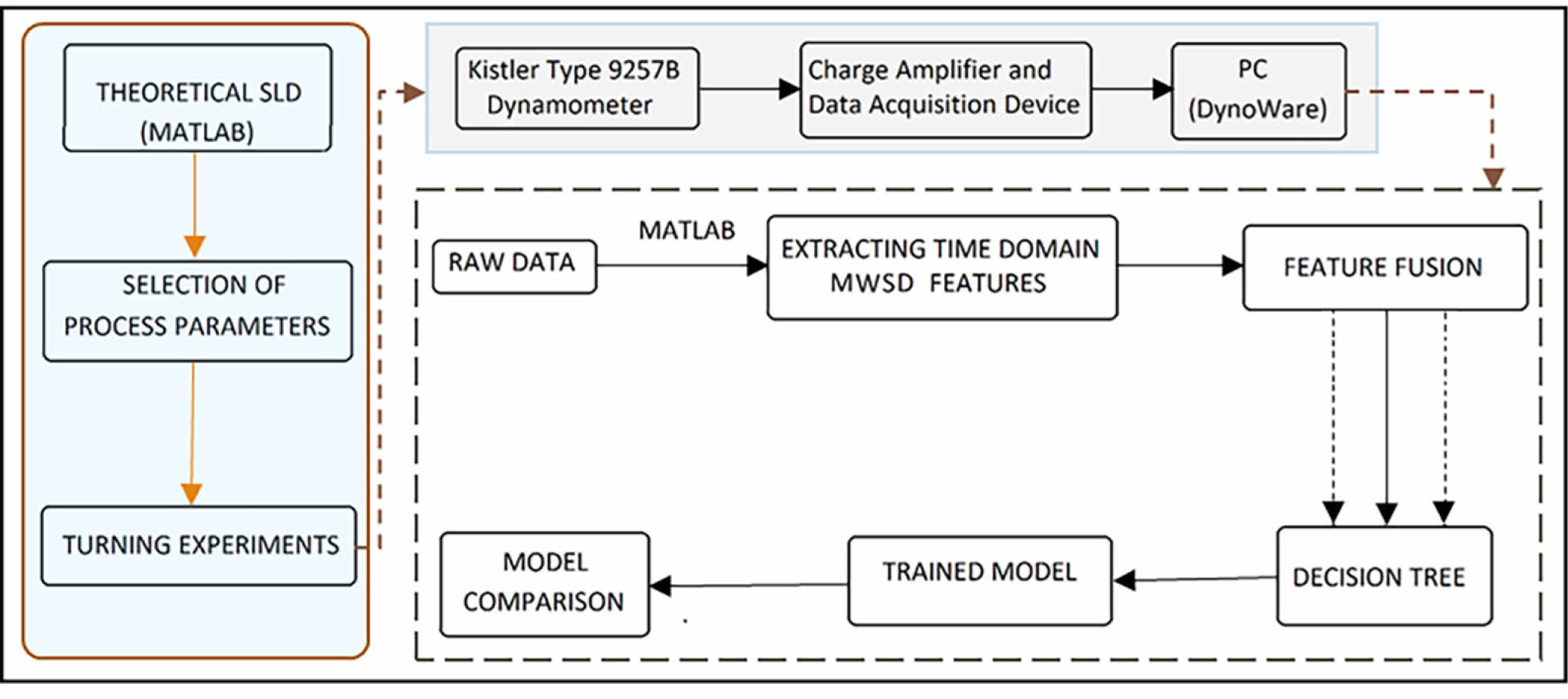
Theoretical SLDs are established for the dry orthogonal turning of the cylindrical EN24 workpiece on a mechanical lathe. An experimental setup is established for the dry orthogonal turning process of EN24. Process parameters are selected on the basis of the theoretical SLDs, which are plots of spindle speed versus depth of cut, for the different chatter conditions. The experiments are conducted on a mechanical lathe and the force signatures are collected using a calibrated dynamometer and data acquisition (DAQ) software. Features of Standard Deviation (SD) & MWSD for different window sizes (5, 10, 50 & 100) are extracted in the time domain for the signals and used for the training of the DT classifier. ML models are trained using the features extracted from the cutting force signals and compared using various performance measures. This experimental methodology is illustrated in Fig. 1.
Development of Theoretical SLDs
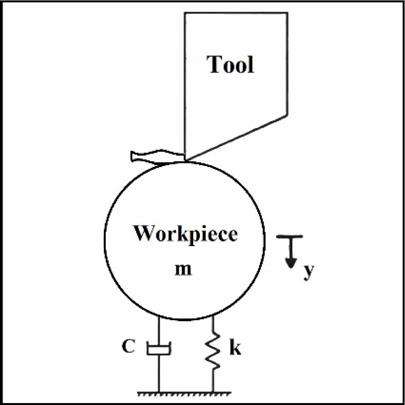
A SDoF vibratory model of orthogonal turning process is given in Fig. 2. The model is assumed to be under viscous damping and only cutting forces of the sharp tool are considered. The vibration is assumed only in the y-direction.
Altintas [3] has previously modeled an SDoF system for orthogonal turning operation and arrived at the following expression for chatter-free machining,
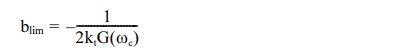
In this equation, blim is the limiting depth of cut above which chatter occurs, kt is the coefficient of feed force component and G(ωc) is the real parts of the transfer function. The chatter-free stability behavior of the process can be predicted by using equations given in conjunction with the measured dynamics and force coefficients.
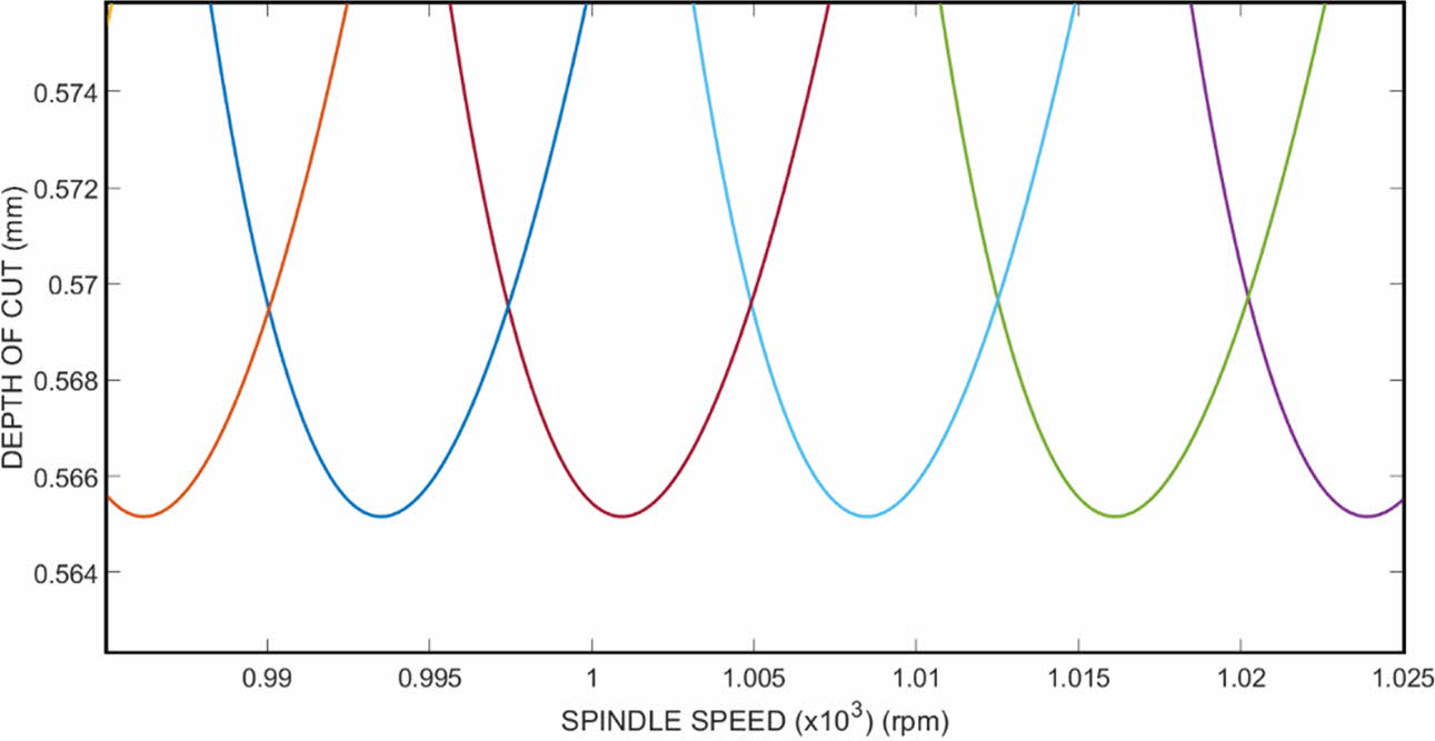
The SLD can be used to predict the stability of chatter in a turning process. A MATLAB program is used to obtain the SLD from the process parameters and force coefficients analytically. The theoretical SLDs for the given workpiece with stick-out length of 100 mm are determined using the previously established relations and plotted using the MATLAB program. The limiting depth of cut values for different levels of spindle speeds can be obtained from the SLD as in Fig. 3. From the SLDs, the limiting depth of cut values for spindle speeds of 400, 1000 & 1600 rpm were found to be 0.5651, 0.5654, 0.5655 mm respectively.
DT Algorithm
DT is a type of supervised machine learning technique widely used in regression or classification models. These models are visualized as a tree structure containing decision nodes, that contain multiple branches and leaf nodes that represent the outcome of those decisions without any further branching. The topmost decision node is known as the root node, which is the representation of the whole dataset, which is further split into multiple homogeneous sets with each upcoming decision node. The model infers and learns decision rules from the training data in order to predict the value of target variables. The CART algorithm is used to construct the DT, by following a set of if-else conditions in order to classify the given data. The DT may split and distribute the dataset using the gini diversity index criterion, the twoing rule criterion, or the maximum deviance reduction criterion.
Experimental Setup
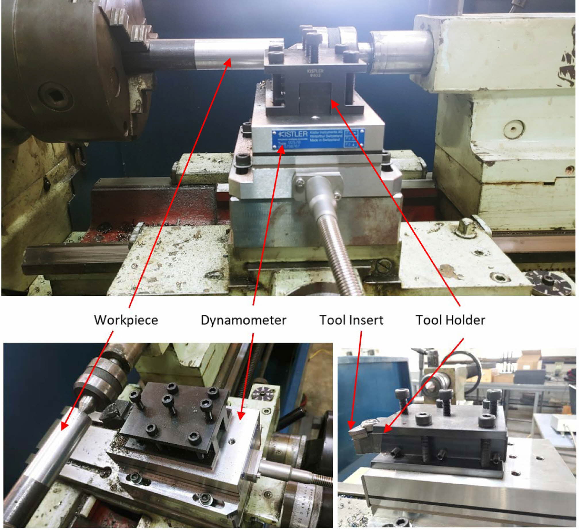
The experimental set-up is established to conduct the experiments as in Fig. 4. The carbide turning tool insert used is PC9030 Grade KORLOY WNMG080408-HA affixed on a right hand WIDAX tool holder, MWLNR 2525 M08. The high-quality carbide turning tool insert boasts a hardness of HRA92.6 with good wear and breakage resistance, and is used for both internal & external turning applications. The workpieces used are 150 mm long cylindrical EN24 rods of 30 mm diameter. The workpiece material is through-hardened high-strength alloy steel. Kistler Type 9257B dynamometer is used for cutting force measurements. It consists of 4 three-component force sensors sandwiched between a top plate and a base plate. The force measured is broken down into three components. The amplifier Kistler LabAmp Type 5167A is used alongside the dynamometer to digitize and process the signals from the piezoelectric sensors. The collection of the dynamometer force data is done on a laptop computer connected to the Kistler LabAmp through the DynoWare data acquisition software. The software is set up as per manufacturer re- commendations and experimental parameter require- ments. A sample rate of 1000 Hz was selected for a measuring time of 20 seconds. The Centre Lathe Turn Master 40 capable of running at eight different spindle speeds ranging from 71 to 1600 rpm is used.
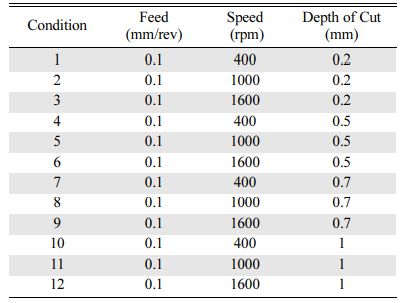
The experiments are conducted under dry cutting conditions on the mechanical lathe. The setup consists of a cylindrical EN24 workpiece mounted into the chuck of the spindle of the lathe. The workpiece overhang is set to 100 mm. Cutting forces are measured using a calibrated multicomponent dynamometer. DynoWare data acquisition software is used to process and collect the force signals through the Charge Amplifier and Data Acquisition Device. The turning process is con- ducted on the workpiece with varying levels of speed, feed, and depth of cut selected from the theoretically established SLDs. The selected process parameters are given in Table 1.
|
Fig. 1 Experimental methodology. |
|
Fig. 2 Modeling of orthogonal turning process. |
|
Fig. 3 Theoretical SLD obtained from MATLAB. |
|
Fig. 4 Experimental setup; Lathe-workpiece-dynamometer-tool setup |
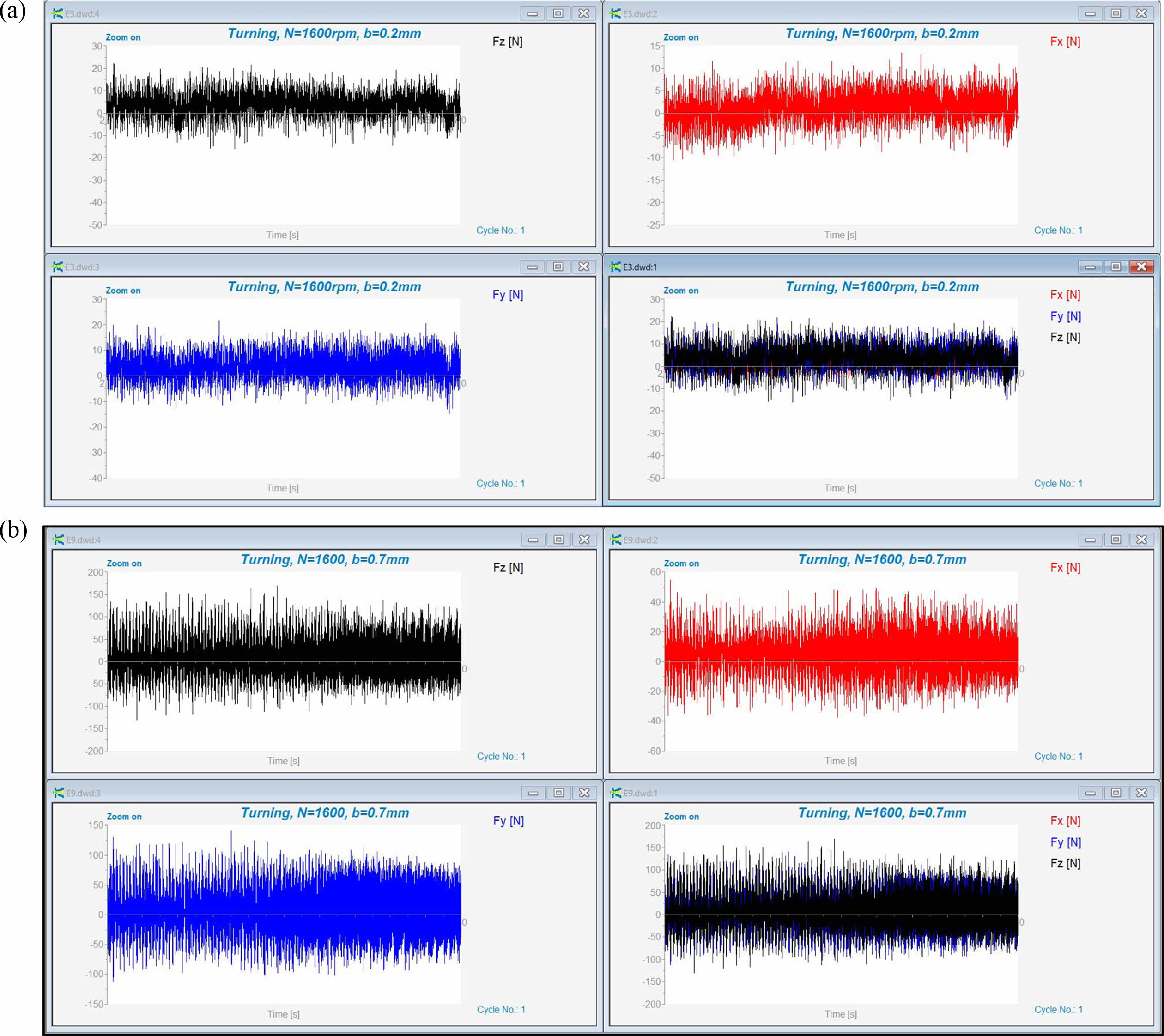
The dynamometer force signal data recorded in the DynoWare software for the 12 turning experiments conducted are shown in Figs. 5(a) and (b). The terms Fx, Fy, and Fz represent the force signals pertaining to radial force, feed force, and cutting force respectively. The cutting force signals were found to have the greatest amplitude, which coincided with what is expected from the literature.
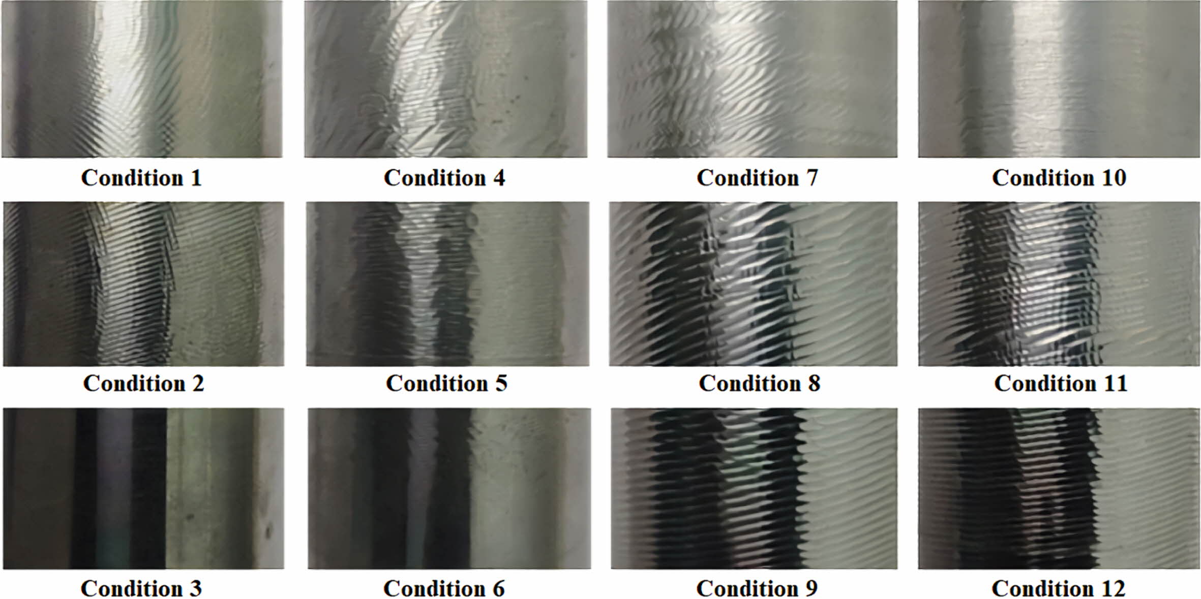
Digital images of the workpiece surfaces were captured using a 32-megapixel digital camera. The captured surface topographies of the workpieces pertaining to each of the 12 experimental conditions are depicted in Fig. 6. The conditions of unstable cutting were distin- guishable from the presence of chatter marks. These chatter marks are indicators of poor surface finish and reduced dimensional accuracy.
Chatter Identification using CART DT Classifier
Feature Extraction
Numerous features can be extracted in the time domain from the cutting force data obtained through the DAQ software. These features are used as datasets for training the classification algorithms. Not all features can provide an accurate depiction of the process condition when used for training models. Unilaterally increasing the number of features used for training the model will not always provide any substantial im- provement to the classifier. In order to decrease the computation time and resource usage, the best features that can effectively depict the process condition are selected for use as datasets for training the ML Models. SD is a statistical feature that has shown good results when used in DT classifiers.
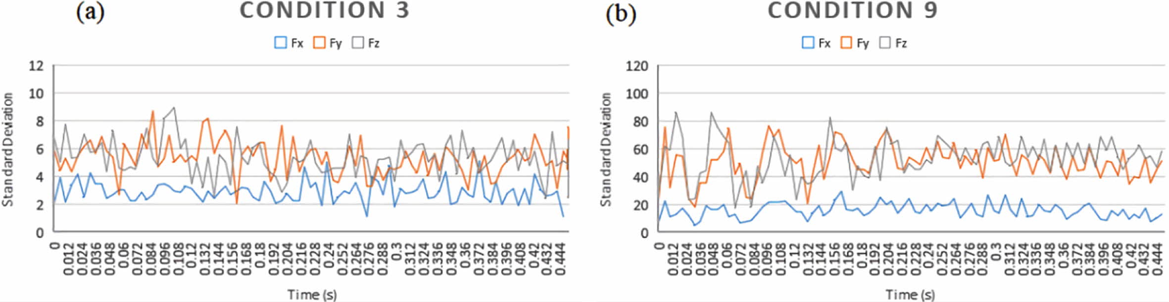
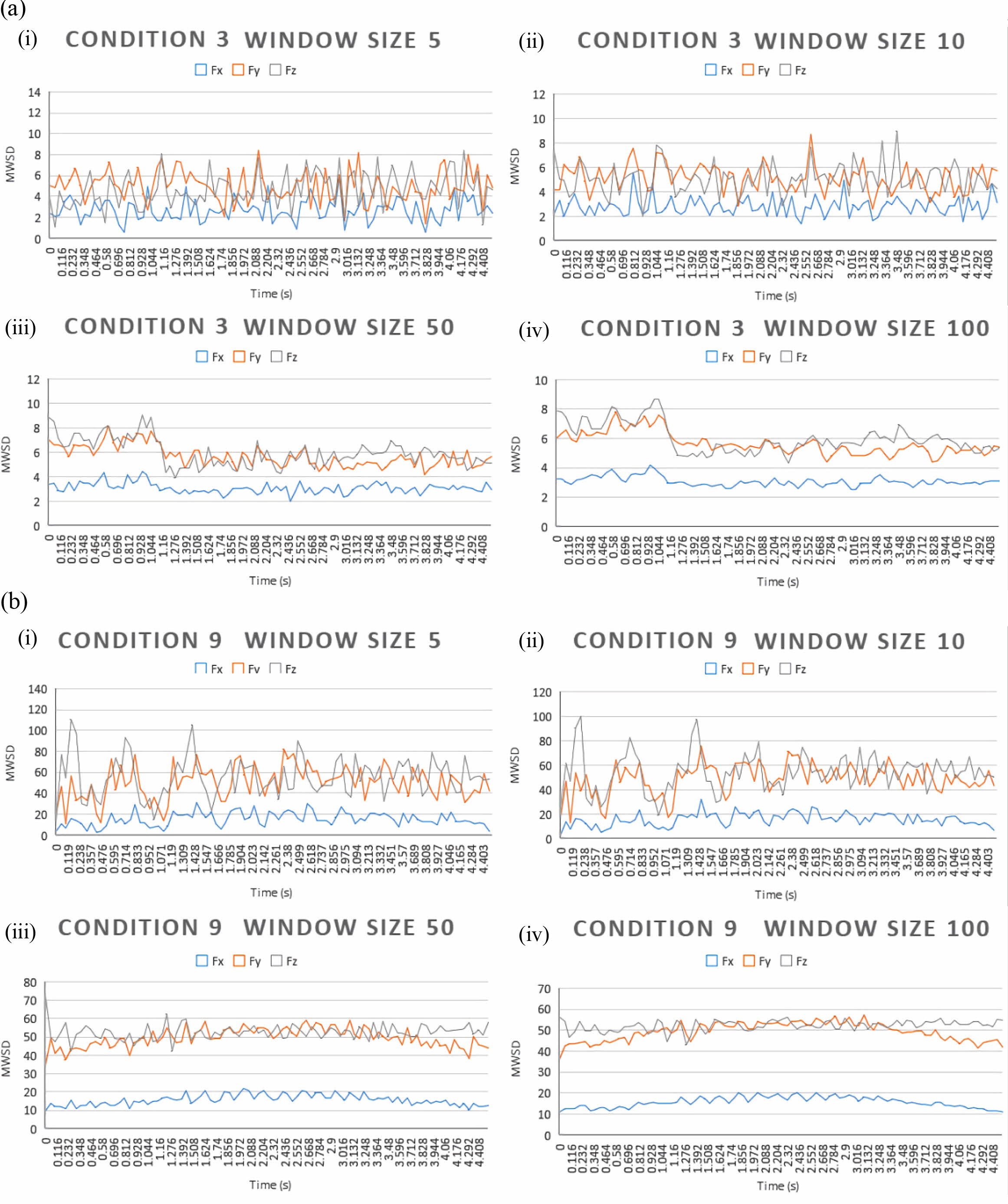
The time-domain force signals obtained from DAQ software were analyzed sequentially over time and the features of SD & MWSD for different window sizes (5, 10, 50, & 100) were extracted from the Fx, Fy & Fz signals for each process condition (12 classes). The SD & MWSD values for conditions 3, & 9 are plotted for comparison in Figs. 7 and 8.
From the evaluation of the data given in Figs. 8(a) and (b), the effects of the window size on MWSD were inferred. Increasing the window size helped in decreasing the noise and resulted in less variation in the MWSD. Moreover, this also led to the response of each of the force signature components becoming more distinct. But raising the window size above a certain limit is not advised as it could result in the loss of resolution.
CART DT Classifier
The MWSD features extracted from the 3 cutting force component signatures (radial force, feed force & cutting force) pertaining to the 12 classes were taken as datasets to train the CART DT classifiers. For conveni- ence, the models trained using the dataset formed from the MWSD feature of window sizes 5, 10, 50 & 100 were named MW-05, MW-10, MW-50 & MW-100 respectively. The normal SD feature dataset was used to train a separate CART DT model for comparison. The DT was constructed using the MATLAB DT toolbox. The optimizable DT algorithm was used where the optimized hyper-parameters were selected iteratively to arrive at the optimum model with the highest classification accuracy. 10-fold cross-validation, which evaluates a complementary subset of the data among the available input data, was used to validate the model. The performance of the trained models was compared with the help of performance measures, viz., classification accuracy, precision, recall, kappa statistics & ROC measure.
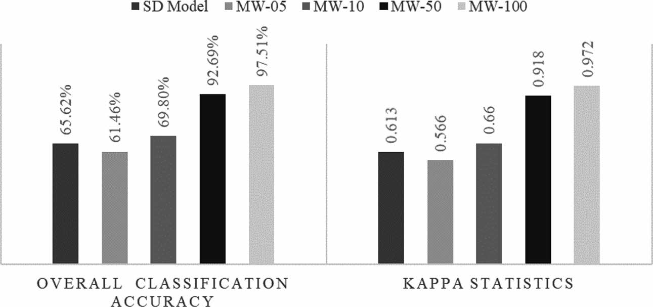
The evaluation of the overall classification accuracy & Kappa statistics value (refer to Fig. 9), shows that the model ‘MW-100’, which was trained using the dataset of MWSD with a window size of 100, displayed the best performance out of all the models. The evaluation of the performance & robustness of the models using the confusion matrices with regards to True Positive Rates (TPR), False Negative Rates (FNR), Positive Predictive Values (PPV), & False Discovery Rates (FDR) further strengthening the validity of these findings. TPR, otherwise referred to as Recall or Sensitivity is a measure of ‘completeness’ of the classifier, and PPV or Precision is the measure of ‘exactness’ of the classifier. The models trained with MWSD datasets of larger window sizes displayed higher TPR & PPV values and lower FNR & FDR values. Thus the classification using these models can be considered to be more comprehensive & precise. The measure of the ‘Area Under Curve (AUC)’ number from the receiver operating characteristic (ROC) curve that plots the true & false positive rates also supports this claim. The models trained with MWSD datasets of larger window sizes displayed higher and more consistent AUC values.
The performance of the model experienced an improvement with the increase in the window size used for the MWSD. Compared to models using normal SD feature datasets, those trained using MWSD feature datasets generally provide better classification accuracy for larger window sizes. The model trained using the dataset with MWSD of window size 100 is found to have the best performance out of the models explored, with a classification accuracy of 97.511%. The model displays very high TPR & PPV and very low FDR & FNR values when compared to the other models. It also has the highest Kappa value of 0.972. The ROC plots also display very high AUC values of 0.99 & 1. Overall, the model has a sufficiently high performance when compared with the other models and the classi- fication accuracy of the model can be improved by increasing the MWSD window size to an optimum value.
|
Fig. 5 (a). Force signature data from Dyno Ware software; Condition 3: Spindle Speed 1600 rpm, Depth of Cut 0.2 mm and (b) Force signature data from Dyno Ware software; Condition 9: Spindle Speed 1600 rpm, Depth of Cut 0.7 mm. |
|
Fig. 6 Digital Imagery; Surface topography of the finished workpieces. |
|
Fig. 7 Time-domain Standard Deviation Plots for conditions 3 & 9. |
|
Fig. 8 (a) Time-domain MWSD Plots for Condition 3 and (b) Time-domain MWSD Plots for Condition 9. |
|
Fig. 9 Comparison of Models; Overall Classification Accuracy & Kappa Statistics. |
Force sensor signatures were captured from a total of 12 experimental conditions with different combinations of spindle speed and depth of cut, during the turning operation on EN24. Signal processing was carried out and statistical features of SD & MWSD with different window sizes were extracted from the time domain signatures of force signal. The models trained using the dataset formed from MWSD feature of window sizes 5, 10, 50 & 100 were found to display classification accuracy of 61.5%, 69.8%, 92.7% & 97.5% respectively.
The analysis of other performance measures such as Recall, Precision, Kappa value, and ROC AUC measures suggest that the models trained using the dataset formed from MWSD provide good performance at larger window sizes. It can be inferred that the feature of MWSD is very effective in training CART DT classifier models for chatter identification. The selection of an optimum window size can aid in reducing the misclassification rates and increasing the robustness of the classifier. Future studies may include the method of selection of an optimum window size that serves to maximize the classification accuracy and reduce classification errors.
The authors declare that there is no conflict of interest.
- 1. G. Quintana, and J. Ciurana, Int. J. Mach. Tools Manuf. 51[5] (2011) 363-376.
-

- 2. C. Yue, H. Gao, X. Liu, S. Y. Liang, and L. Wang. Chinese J, Aeronaut. 32[2] (2019) 215-242.
-
- 3. Y. Altintas, in “Manufacturing Automation: Metal Cutting Mechanics, Machine Tool Vibrations, and CNC Design” (Cambridge University Press, 2001) p. 1.
-
- 4. D. Tang, H. B. Lim, K. J. Lee, S. J. Ha, K. B. Kim, M. W. Cho, K. Park, and W. S. Cho, J. Ceram. Process. Res. 14[5] (2013) 610-615.
- 5. B. G. Lee, and K. E. Kim, J. Ceram. Process. Res. 10[4] (2009) 482-490.
- 6. K. K. Senthil, R. Thirumalai, M. Seenivasan, and T. Venugopal, J. Ceram. Process. Res. 22[6] (2021) 731-738.
-
- 7. A. Kumar, M. Kumar, and R. Singh, Int. J. Appl. Eng. Res. 13[13] (2018) 11069-11076.
- 8. N. Subhash, T. Jagadeesha, and M. Law, Int. J. Mach. Mach. Mater. 22[5] (2020) 386-405.
-
- 9. F. Aggogeri, N. Pellegrini, and F. L. Tagliani, Appl. Sci. 11[18] (2021) 8764.
-
- 10. T. Mohanraj, S. Shankar, R. Rajasekar, N. R. Sakthivel, and A. Pramanik, J. Mater. Res. Technol. 9[1] (2020) 1032-1042.
-
- 11. Y. S. Chuo, J. W. Lee, C. H. Mun, I. W. Noh, S. Rezvani, D. C. Kim, J. Lee, S. W. Lee, and S. S. Park, J. Mech. Sci. Technol. 36[1] (2022) 1-23.
-
- 12. H. N. Gao, D. H. Shen, L. Yu, and W. C. Zhang, Int. J. Simul. Model. 19[4] (2020) 667-677.
-
- 13. J. Tlusty and G. C. Andrews, CIRP Ann. - Manuf. Technol. 32[2] (1983) 563-572.
-
- 14. E. Kuljanic, M. Sortino, and G. Totis, J. Sound Vib. 312[4-5] (2008) 672-693.
-
- 15. A. Arun, K. Rameshkumar, D. Unnikrishnan, and A. Sumesh, Mater. Today Proc. 5[5] (2018) 11888-11899.
-
- 16. D. S. B. Mouli and K. Rameshkumar, in “Advances in Materials and Manufacturing Engineering. Lecture Notes in Mechanical Engineering” (Springer Singapore, 2020) pp. 353-359.
-
- 17. S.K. Thangarasu, S. Shankar, T. Mohanraj, and K. Devendran, Proc. Inst. Mech. Eng. Part C J. Mech. Eng. Sci. 234[1] (2020) 329-342.
-
- 18. R. U. Baig, S. Javed, M. Khaisar, M. Shakoor, and P. Raja, Adv. Mech. Eng. 13[6] (2021) 1-14.
-
- 19. S. Saravanamurugan, S. Thiyagu, N. R. Sakthivel, and B. B. Nair, Int. J. Manuf. Res. 12[4] (2017) 405-422.
-
- 20. P. Krishnakumar, K. Rameshkumar, and K. I. Ramachandran, Int. J. Progn. Heal. Manag. 9[1] (2018) 1-15.
- 21. J. H. Ko, Metals. 12[2] (2022) 298.
-
- 22. D. Das, S. Mukherjee, S. Dutt, B. Bijeta Nayak, and A. Kumar Sahoo, Mater. Today Proc. 5[2] (2018) 4097-4105.
-
- 23. S. Ravi Teja, N. C. Swapna Sri, G. P. Chaitanya, C. Vishnu Teja, Bhavana, A. Tewari, and S. Saikumar, Mater. Today Proc. 5[13] (2018) 27051-27057.
-
- 24. S. Kalyanakumar, S. T. Chandy, K. T. Adil Muhammed, and P. S. Rohith, Mater. Today Proc. 45 (2020) 6193-6197.
-
- 25. G. Venkata Ajay Kumar, A. Ramaa, and M. Shilpa, Decis. Sci. Lett. 11[2] (2022) 193-202.
-
- 26. N. Saravanan and K. I. Ramachandran, Expert Syst.Appl. 36[5] (2009) 9564-9573.
-
- 27. M. Elangovan, K. I. Ramachandran, and V. Sugumaran, Expert Syst.Appl. 37[3] (2010) 2059-2065.
-
- 28. R. Thirumalai, and M. Vivekraj, J. Ceram. Process. Res. 23[2] (2022) 228-232.
-
- 29. R. Thirumalai, S. Karthick, and M. Giriraj, J. Ceram. Process. Res. 23[2] (2022) 221-227.
-
- 30. Mukesh Kumar, S.K. Tamang, Dipika Devi, M. Dabi, K. K. Prasad, and R. Thirumalai, J. Ceram. Process. Res. 23[2] (2022) 373-382.
-
- 31. M. Sivaperumal, R. Thirumalai, S. Kannan, and K. S. S. Rao Yarrapragada, J. Ceram. Process. Res. 23[2] (2022) 404-408.
-
 This Article
-
2022; 23(4): 503-510
Published on Aug 31, 2022
- 10.36410/jcpr.2022.23.4.503
- Received on Feb 11, 2022
- Revised on Mar 7, 2022
- Accepted on Mar 10, 2022
Services
- Abstract
introduction
methodology
results & discussions
conclusion
- Declaration of Interest
- References
- Full Text PDF
Shared
Correspondence to
- S. Saravanamurugan
-
Department of Mechanical Engineering, Amrita School of Engineering, Coimbatore, Amrita Vishwa Vidyapeetham, India
- E-mail: s_saravana@cb.amrita.edu
Clean-Energy Research Institute(CRI), Hanyang University, 222, Wangsimni-ro, Seongdong-gu, Seoul, 04763, Korea
E-mail: jcpr@hanyang.ac.kr