


- Test research and performance analysis of the mountain-shaped retreating terrace style lapping column transfer structure
Zhicheng Bai, Xiaoxia Zhao*, Baoan Zhang, Yang Yang, Zhiyuan Zhang and Yongyan Li
China Construction Fourth Engineering Bureau Co., Ltd. Guangzhou 510000, Guangdong, China
This article is an open access article distributed under the terms of the Creative Commons Attribution Non-Commercial License (http://creativecommons.org/licenses/by-nc/4.0) which permits unrestricted non-commercial use, distribution, and reproduction in any medium, provided the original work is properly cited.
To investigate the mechanical behavior of column transfer structures enhanced by ceramic composite materials, the characteristics of the mountain shaped retreating terrace style lapping column transfer structure in a certain museum in Hangzhou, one of the three-layer and three-bay lapping column was taken as the main research object. Static and quasi-static tests were carried out respectively on 1:5 scale model specimens, and the static and quasi-static characteristics of the mountain-shaped retreating terrace style lapping column transfer structure were analyzed. Finite element simulations were also conducted to validate experimental observations. Results showed that under 1.2 times the design vertical load, the specimen remained in the elastic range with no visible cracking, indicating excellent load-bearing capacity. Furthermore, the inclusion of ceramic materials significantly improved the hysteretic behavior and energy dissipation performance of the joint under cyclic lateral loading. The peak inter-story drift ratio reached 1/28 without structural failure, meeting seismic performance requirements. This study provides useful insights into the integration of ceramic-based composites in complex structural transfer systems for improved resilience.
Keywords: Mountain-shaped retreating terrace style, Lapping column transfer structure, 1:5 scale model, Static characteristic, Quasi-static characteristic.
Lapping column transfer structure as a new type of high rise building structural transfer system, which was primarily used to address the misalignment of column grids between upper and lower floors [1]. It was especially applicable to complex building forms with facade setback or outward expansion. The lapping column transfer structure has the following advantages compared with beam type transfer, thick plate transfer, etc [2]. First, the building space of the transfer layer had a high utilization rate. Second, the consumption of main building materials was relatively low. Third, the structural force bearing was clear and force transfer was relatively direct. Fourth, the lateral stiffness mutation of the structure was relatively small, which was beneficial to seismic resistance. In recent years, projects constructed using this structural form included the Fujian Industrial Bank Tower, Nanjing Golden Eagle International Mall, China Ping An Insurance Customer Service and Backup Technical Center, Tianhe Fangyuan Business Hotel, and Petronas Towers in Kuala Lumpur, Malaysia, etc [3]. However, the lapping column transfer structure also had its own key and difficult points. On the one hand, the splice block’s upper and lower floor structures were subjected to significant tensile forces, and attention should be paid to the risk of cracking. On the other hand, the lapping structure area simultaneously bore the combined effects of bending moment, shear force, axial force, and torque, and needs to be carefully designed and constructed according to the stress characteristics. Therefore, many scholars have carried out a series of studies on the lapping column transfer structure.
Lin et al. [3] used ABAQUS to establish a refined model and conducted quasi-static tests on the scaled model. The parametric influence laws of the lapping column transfer structure with built in steel sections were studied. Some scholars [4-6] have conducted vibration table model tests, finite element analysis, and static loading tests on the overlapped column transfer layer of Fujian Industrial Bank Building. The seismic performance, force bearing characteristics, and failure modes of the lapped columns in this project were systematically studied. Quan et al. [7] conducted a graded vertical loading test on a 1:4 scale model of a lapped column. The force transfer mechanism, deformation characteristics, and stress characteristics of the lapping column model were analyzed. Shen et al. [8, 9] systematically analyzed the mechanical characteristics and seismic performance of the lapping column transfer system through finite element simulations and shaking table tests. Lv et al. [10] studied the failure mode and seismic performance of a large chassis multi tower model with 1:15 lapping column transfer structure through shaking table tests. A detailed analysis and verification of the mechanical characteristics and seismic performance of the lapping column transfer structure had been conducted in these studies.
In addition, with the increasing number of projects in which the lapping column transfer structures were designed and used, the unique design forms and characteristics of the lapping column in each project had also been studied. Huang et al. [11] introduced design form of the lapping column transfer structure in Hangzhou Yintai City. Fu and Xu [12] used SATWE and MIDAS to conduct deformation and stress analyses of the structural design features of lapping column of building 41C in No.41 neighborhood of Suhe Creek. Yan et al. [13] used SAP2000 to analyze the mechanical properties of the lapping column transfer structure in a certain engineering project. Xue and Zhao [14] used the ABAQUS software to conduct an elastoplastic analysis of the key transfer joints focused on the design key points of the lapping column transfer structure in a commercial project in Beijing. Song et al. [15] conducted a comparative analysis of three types of transfer column structures with facade setbacks designed for a certain super high rise building. Li [16] analyzed and checked the horizontal force components, progressive collapse resistance, and key joints of the lapping column structure of a super high rise tower with facade setback. The feasibility and safety of the structural design were verified. Ding et al. [17] conducted a detailed finite element analysis of the lapping column transfer structure of a certain super high rise building.
Although a detailed analysis and verification of the mechanical characteristics and seismic performance of the lapping column transfer structure had been conducted in these studies by scale model specimens. The structural form primarily features a vertical facade and did not involve a retreating terrace style lapping column transfer structure. Therefore, further research is needed on the mechanical performance of the mountain-shaped retreating terrace style lapping column transfer structure.
Relying on the characteristics of the mountain shaped retreating terrace style lapping column transfer structure in a certain museum in Hangzhou, one of the three-layer and three-bay lapping column is taken as the main research object. Static and quasi-static tests are carried out respectively on 1:5 scale model specimens, and the static and quasi-static characteristics of the lapping column transfer structure are analyzed. Furthermore, finite element software is utilized to conduct a simulated comparative analysis, aiming to verify the reliability of the structural design.
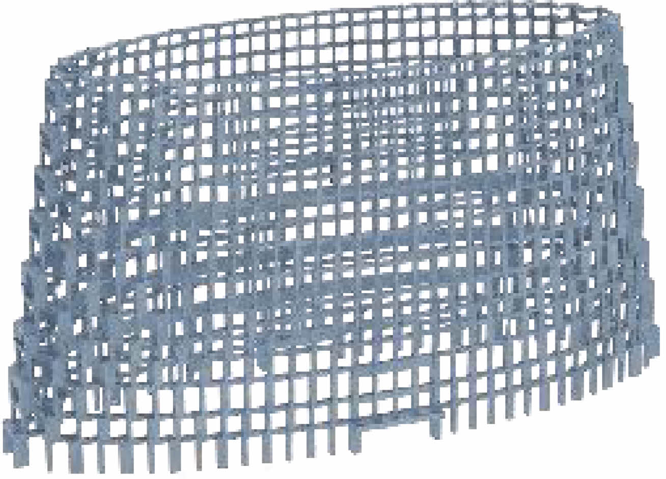
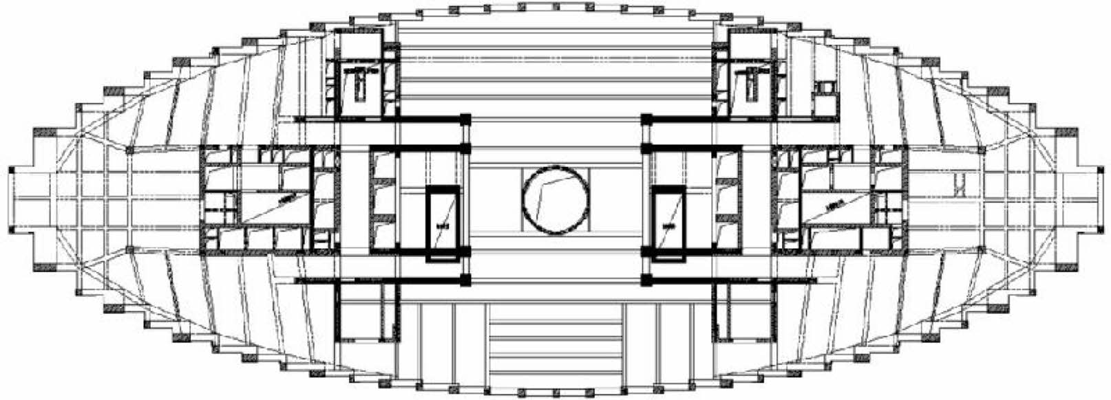
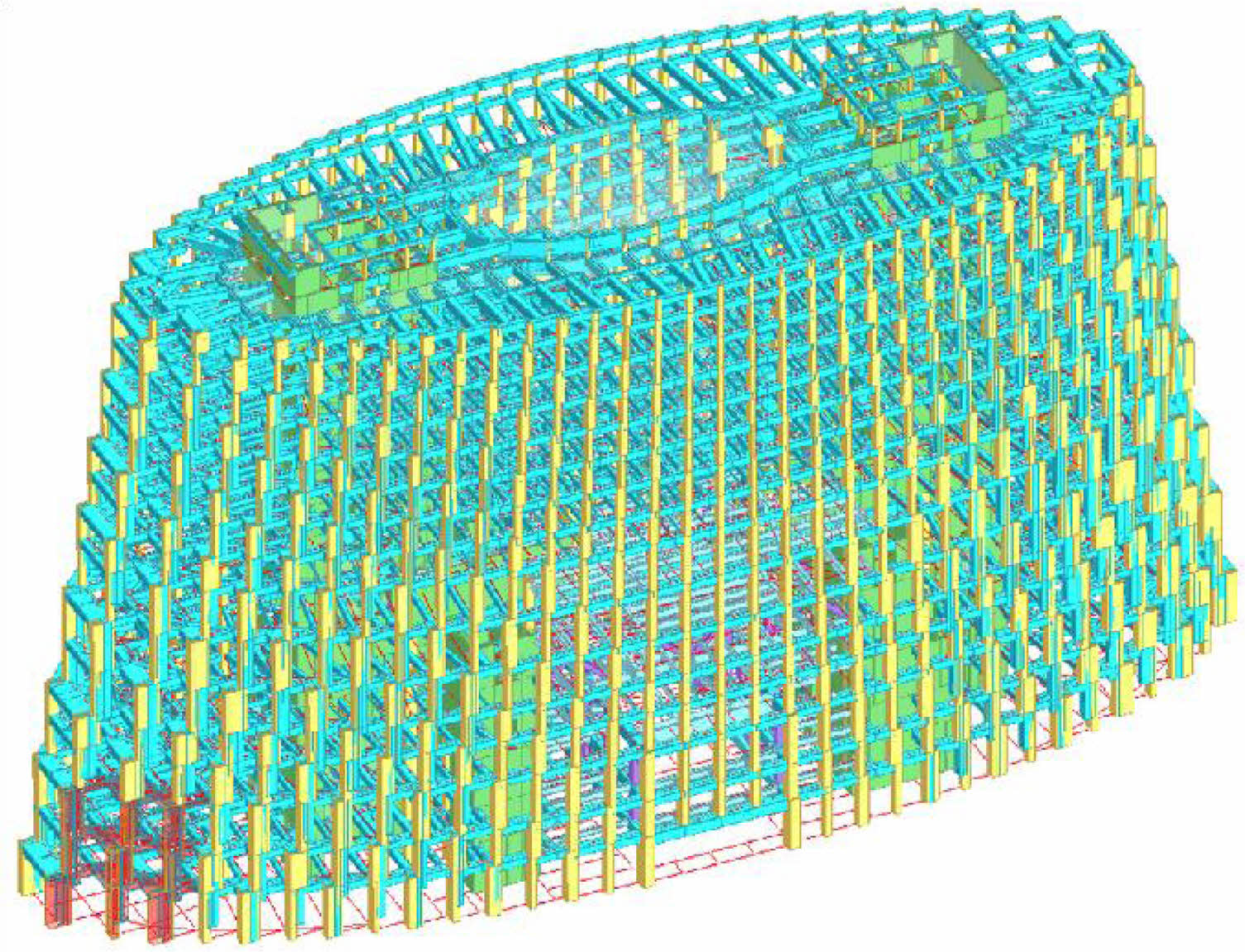
The project of a certain museum as a comprehensive building integrating ‘tourism’ and ‘learning’ in Hangzhou, which is composed of a central tower and podium buildings around it. Among them, the tower is a frame core tube structure with 2 underground floors and 15 above ground floors, with a total height of 73.5 m (Fig. 1). The safety level of the building structure is grade-1, the fortification intensity is 7 degree, and the designed basic seismic acceleration is 0.10 g. The exterior facade of the tower is in a stepped inward shape from bottom to top, consisting of alternating large and small overlapping columns in the height direction, achieving the effect of ‘stacking stones into mountains’ (Fig. 2). The lapping columns on the horizontal plane are connected to form an elliptical cylinder, and the upper and lower overlapping columns are connected by horizontal and vertical folding beams, with arc beams set inside the folding beams (Fig. 3).

|
Fig. 1 Rendering of a museum project in Hangzhou. |
|
Fig. 2 Mountain-shaped retreating terrace style lapping column transfer structure. |
|
Fig. 3 Plan of the lapping column transfer structure. |
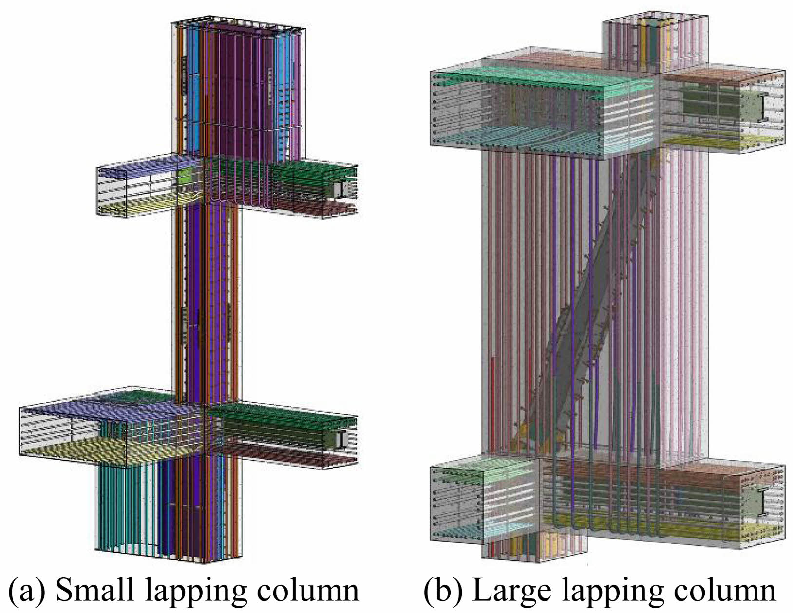
The connecting columns at the base of the mountain-shaped tower experience the most significant cross-sectional changes and the greatest deviations under the upper load. In order to verify the mechanical performance of the lapping column transfer structure, a sub structure composed of a three-layer and three-bay lapping column in the red area of Fig. 4 is selected. The concrete lapping column transfer structure is difficult to withstand the effects of complex internal forces. During design, steel sections are embedded in beam and column components to enhance the load bearing capacity of the transfer structure. The three dimensional reinforcement diagram of large and small lapping columns is shown in Fig. 5.
Scale Model Design
Two scale models are designed and fabricated for conducting static and quasi-static tests on lapping columns, with a size ratio of 1:5. The reinforcement ratio and steel content of the scaled section remain unchanged. Among them, the upper part column top extends upward to 300 mm above the upper edge of the beam section. The lapping columns are made of self-compacting concrete with a strength grade of C60. The thickness of the concrete cover is taken as 10 mm. The longitudinal and stirrup bars of grade HRB400 are arranged in the cross section, and the section steel adopts Q390. The thickness of the concrete cover is taken as 10mm. The longitudinal and stirrup - bars of grade HRB400 are arranged in the cross - section, and the section steel adopts Q390. The parameters are shown in Table 1, and the scale formed specimens are shown in Fig. 6.
Static Test Scheme
The static force test is loaded by the reaction frame loading device, and the distribution beam is loaded through the vertical actuator. The load is transferred to the tops of three columns through distribution beam and three small jacks. Among them, the column top can simultaneously bear the same vertical load when three small jacks were connected to the same oil circuit.
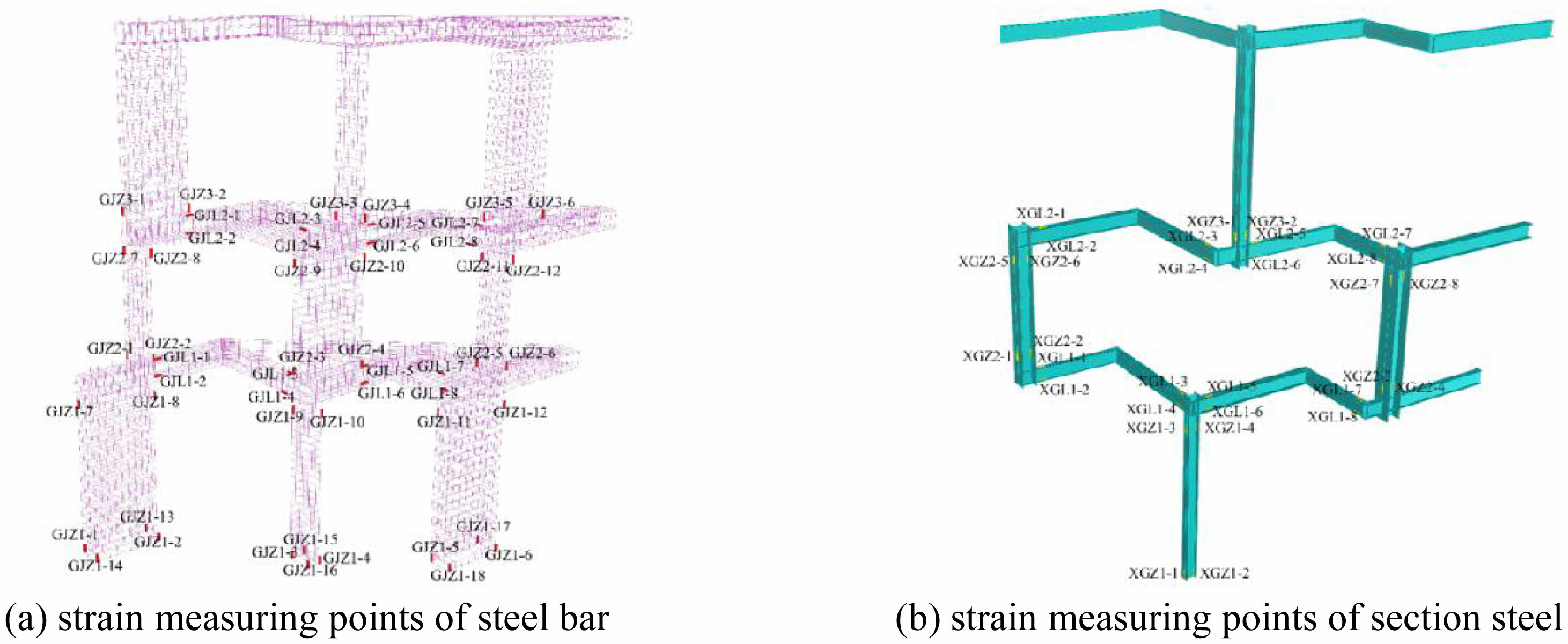
Strain gauges are arranged on the surfaces of the steel bars and sections to monitor their stress changes. It is mainly arranged at the top and bottom of columns and around the junctions of beams and columns. The specific layout of the monitoring points is shown in Fig. 7.
Support devices that constrain unidirectional horizontal displacement are installed at the turning point of the second layer beam, the right end of the first layer, the right end of the second layer, the right end of the third layer, the left end of the third layer, the left end of the second layer, and the left end of the first layer, respectively. They are used to simulate boundary conditions. In addition, the lapping column bottom and 300 mm thick base plate are cast in situ as a whole, and the base plate and the ground are fixed by 8 bolts. And support rods are respectively set at the left and right ends of the first floor to the third floor and at the turning point of the second floor beam to restrict its one way horizontal displacement. Steel bars at the supporting points are exposed and welded with steel plates. Supporting rods are made of round steel pipes with adjustable lengths, and supporting rods are hinged to the steel plates.
The axial forces of three columns at the bottom of the first floor column of the original structure are respectively 19694.3 kN, 16486.8 kN and 18178.0 kN under the basic combination of 1.43 dead load and 1.65 live load, and the resultant force is 54359 kN. The resultant value of vertical load after 1:5 scale is 2174 kN, which is the design load value when loading. Firstly, the load ratio of column 1:column 2:column 3 is 1:1:1. The loading method is monotonic and continuous loading. Preload to 200 kN is carried out before formal loading. Unloading should be carried out after the support is stable and the instruments and loading equipment are in normal condition. Loading system can be seen in Table 2.
Quasi-Static Test Scheme
The reaction frame loading device is still adopted when conducting quasi-static test. Vertical loading is applied to the distribution beam through a vertical actuator, and the horizontal actuator is connected to the beam column joint at the top of column 1 of the third storey column in the model. Vertical load and horizontal load are applied synchronously until the specimen is damaged during the test.
Before the test, the arrangement of strain gauges for reinforcement and section steel is consistent with the static test scheme, as shown in Figs. 7(a) and 7(b) in detail. Guyed displacement meters are respectively arranged at the beam column node of the first layer column 1 and the beam column node of the second layer column 1 of the model. Other guyed displacement meters are arranged at the east and west side of the beam column node of column 1 on the third floor respectively. The other end of the pull wire displacement meter is fixed to the south reaction wall to measure the horizontal displacement of each layer of the model.
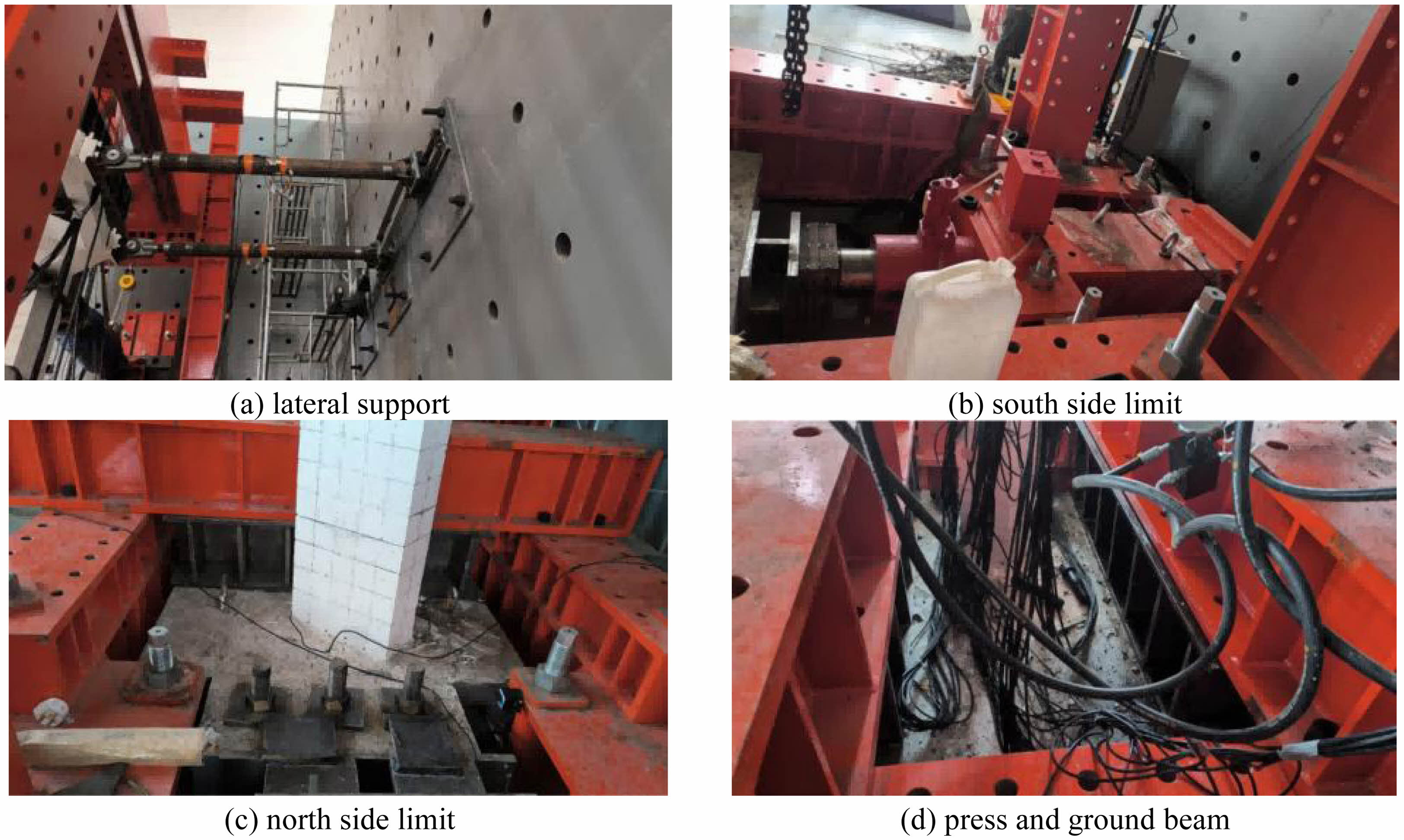
Two lateral support rods perpendicular to the reaction wall are set at both ends of the beam 6 on the third layer of the model during the test. The support rod is hinged to the model, and the bottom of the support rod is connected to the slider. The active actuator is connected to the slider and can push the support rod to move horizontally along with the model. Jack is used to support the model base plate in the south, and a limit member is placed between the model base plate and the trench in the north. The ground beam and the trough are anchored, and the pressure beam and the ground beam are connected by high-strength bolts.
As shown in Fig. 8, horizontal load is defined as positive when it was directed towards the reaction wall (towards the south). Axial forces of the left, middle and right columns of the original structure under 1.0 times of dead load are 10104 kN, 8622 kN and 8614 kN respectively. Axial forces under 1.0 times live load are 1163.7 kN, 1054.4 kN and 953.3 kN respectively. Under the action of 1.0 dead load+0.5 live load, axial force at the bottom of the three columns on the third floor of the original structure is 28925 kN, which is 1150 kN after scaling. Three small jacks under the distribution beam are connected to the same oil circuit, and vertical load ratio at the tops of the three columns is maintained at 1:1:1.
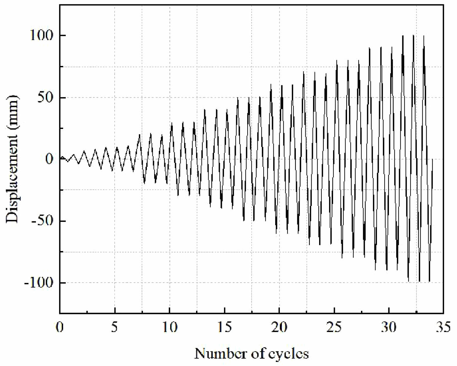
Displacement of the horizontal actuator is set to 0 and added the vertical load to 1150 kN during the test (1.0 dead load+0.5 live load). The vertical load is unchanged and horizontal displacement is started to apply. The horizontal loading is first cyclically loaded once with displacement amplitudes of 2 mm, 4 mm, 6 mm, and 8mm, respectively. Then the load shall be applied with a multiple of 10 mm as the amplitude, and the displacement of each stage shall be cycled three times. The classification of horizontal loading displacement is shown in Table 3, and the horizontal loading system is shown in Fig. 9.
|
Fig. 4 Selected location of the lapping column structure. |
|
Fig. 5 Three dimensional reinforcement schematic diagram of lapping column. |
|
Fig. 6 Scale model (1:5). |
|
Fig. 7 Layout of monitoring points. |
|
Fig. 8 Boundary condition setting. |
|
Fig. 9 Horizontal loading system of quasi-static test. |
|
Table 3 Classification of horizontal loading displacement in quasi-static test. |

Analysis of Static Test Results
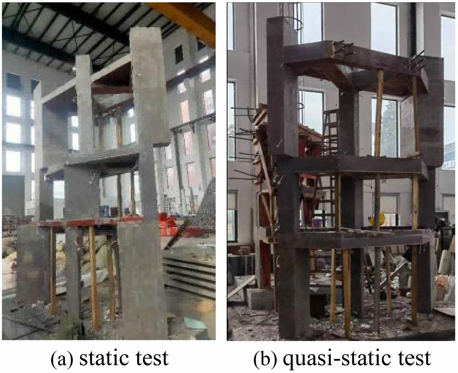
The apparent morphology of the scaled specimen is presented in Fig. 10. No obvious concrete cracks are observed on the surface of the specimen when the load on the top of the column was equal to 1.2 times the design value.
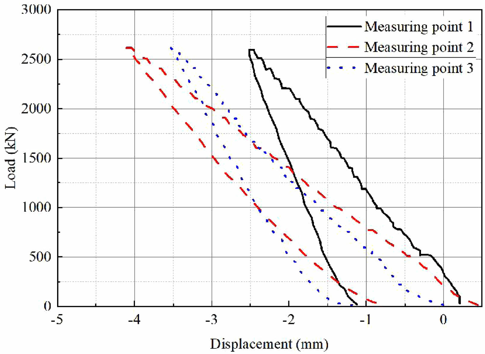
The load-displacement curve relationship of the third layer of the scale specimen under static load is shown in Fig. 11. It can be seen that when the load is gradually increased to 2600 kN, the maximum displacement amounts generated in the first, second, and third floors are -2.5 mm, -4.1 mm, and -3.5 mm, respectively. The final cumulative displacements generated in each layer are all close to -1.0 mm with the completion of unloading, and the structural deformation is relatively stable.
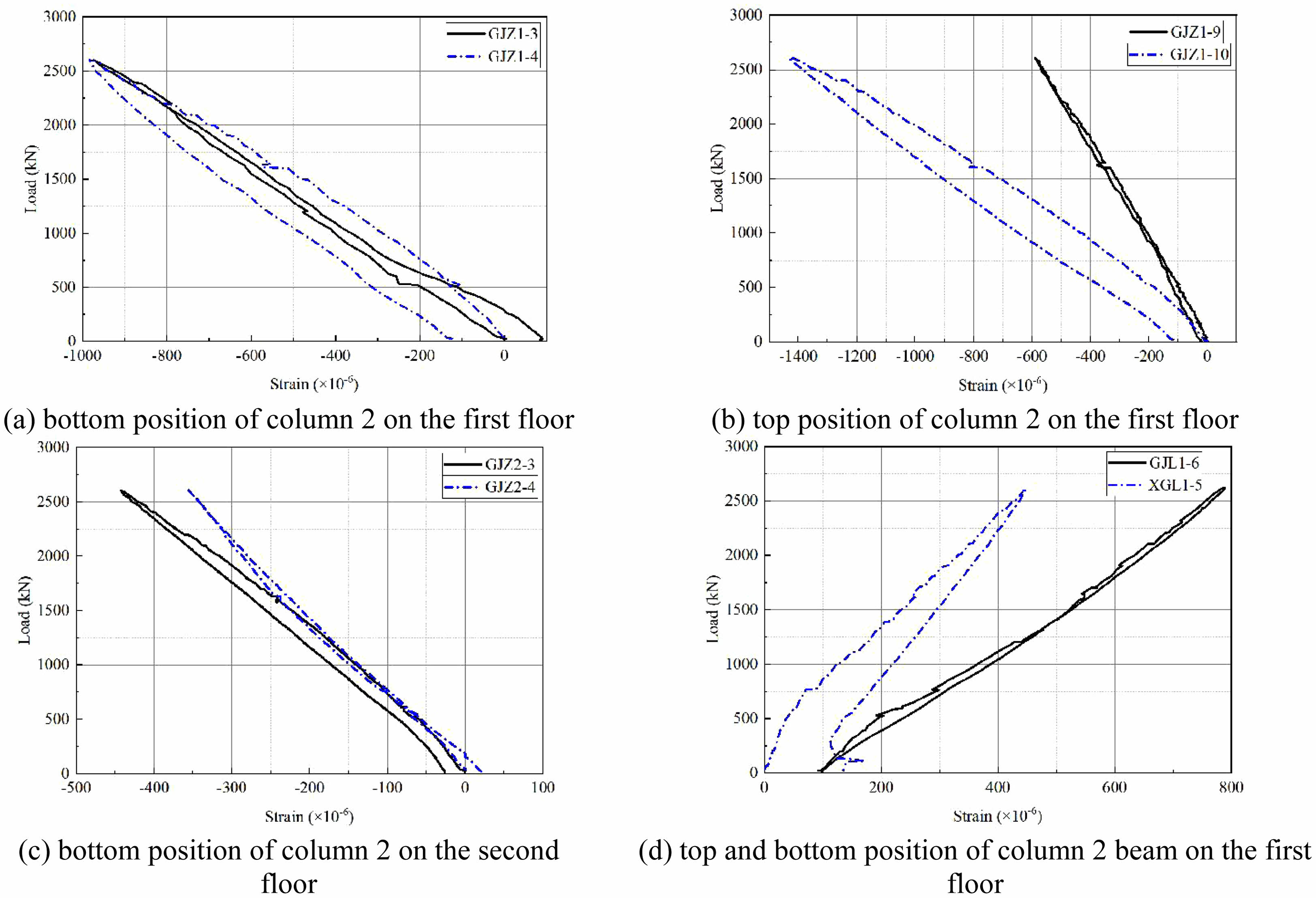
The load strain curve relationship of different parts of the scale specimen under static load is shown in Fig. 12. It can be found that the maximum strains at the two measuring points at the bottom of the middle column on the first floor are respectively -974×10-6 and -982×10-6 when the load increases to 2600 kN step by step. The maximum strains at the two measuring points on the top of the middle column of the first layer are -590×10-6 and -1428×10-6, respectively. The maximum strains at the two measuring points at the column base of the middle column on the second floor are respectively -483×10-6 and -356×10-6. The maximum strains at the two measuring points on the top and bottom of the beam of the middle column on the first floor are 776×10-6 and 442×10-6, respectively. The maximum strain is occurred at the top of the middle column on the first floor. The elastic modulus is taken as 2×10⁵ MPa, and the stress is calculated as -285.6 MPa. In addition, neither the steel bars nor the section steel at the strain measuring points reach the yield strain of 0.2% during the loading process.
Analysis of Quasi-Static Test Results
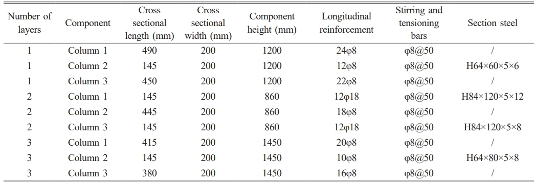
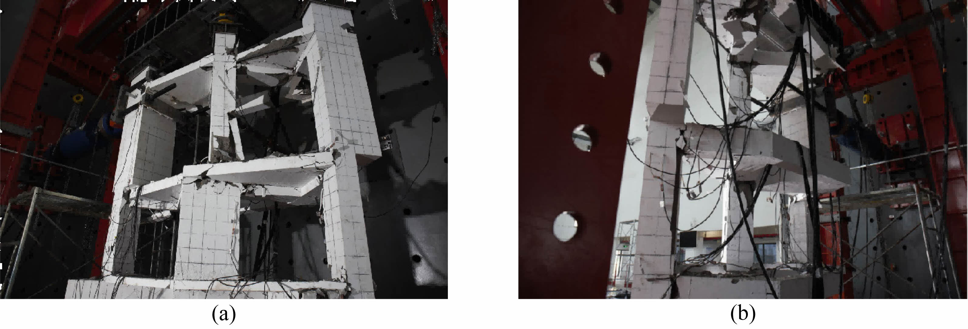
As shown in Fig. 13, concrete cracks are observed for the first time when the horizontal load was -8 mm, which appear on the top of column 2, beam 3 and beam 4 on the first floor. The concrete cracks continue to develop and concrete spalling occurs in multiple locations as the horizontal displacement increases step by step. The concrete of the third layer beam 1, the joint of the third layer beam 4 and beam 5, and the second layer beam 1 is severely damaged when loaded to +70 mm, and the steel bars are exposed.
The jack needs to apply an additional 58.6 kN horizontal load to simulate the supporting effect of the structure other than the three lapping columns before the horizontal displacement is applied. The purpose of this is to ensure that model remains stationary in the horizontal direction when the vertical load was applied. However, this initial horizontal load needs to be subtracted when analyzing the seismic performance of the model.
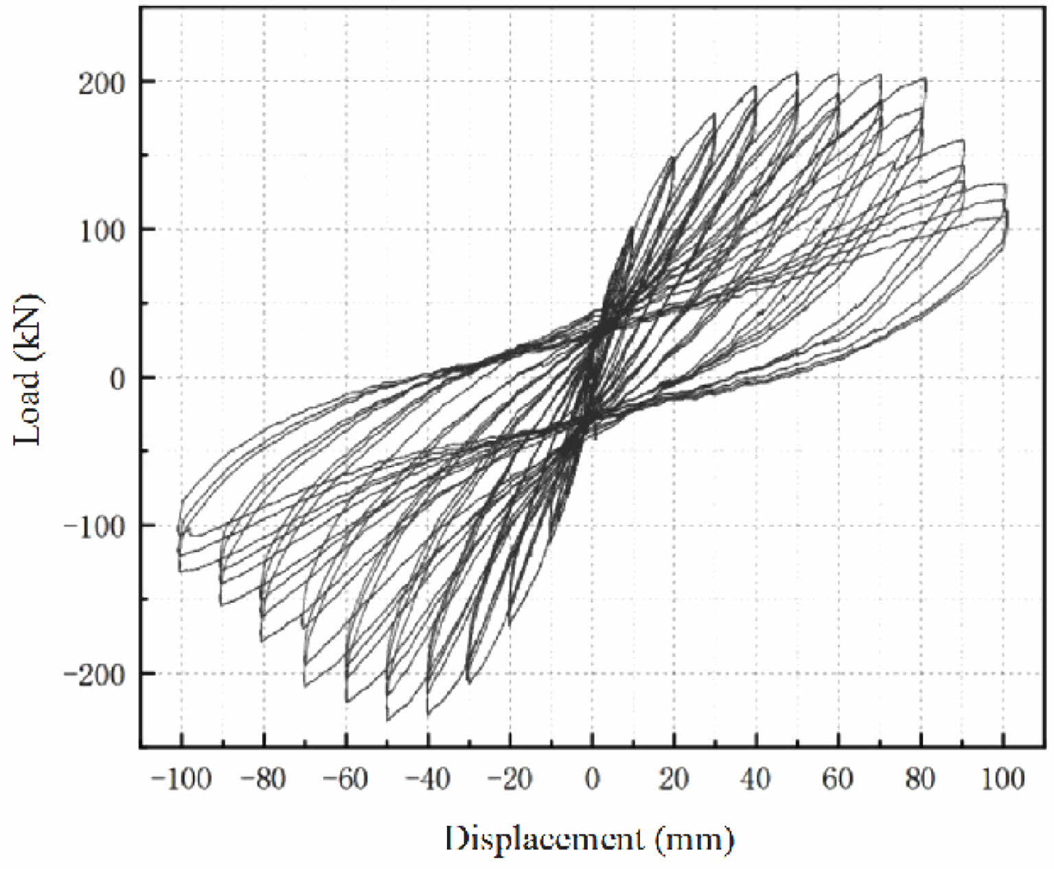
Load-displacement hysteresis curve and skeleton curve (DJZ2) corresponding to the horizontal load of the model and the horizontal displacement of the third floor are shown in Figs. 14 and 15 respectively. It is found that the hysteresis curve and skeleton curve of the lapping column 2 are relatively full. In other words, it is proved that the structure has good energy dissipation capacity. The hysteresis loop curve shows a typical ‘bow’, indicating that the energy consumption of the specimen is good. Furthermore, the hysteresis loop gradually develops into an anti-S shape, indicating that the hysteresis energy consumption of the specimen decreased.
Ductility is an important index reflecting the plastic deformation capacity of structures or members. Good ductility helps the structure absorb and dissipate seismic energy, avoiding brittle failure. The displacement ductility coefficient μ is used to characterize the ductility of the specimen during loading.
In the formula, Δu is the ultimate displacement, and Δy is the yield displacement.
The energy equivalence method is adopted to determine the yield displacement Δy and the yield load Fy. The corresponding displacement and load are respectively the ultimate displacement Δu and the ultimate load Fu when the horizontal load decreased to 85% of the peak load FP during the loading process. The model ductility analysis data shown in Table 4 can be obtained after the calculation of equation (1). The displacement values and inter story displacement angles of the third layer corresponding to the measured model under yield load, peak load and ultimate load are shown in Table 5.
It can be seen from the above table that the inter story displacement angle corresponding to the positive horizontal limit load of the model is 1/28, and the inter story displacement angle corresponding to the negative horizontal limit load is 1/32. Although these data are greater than 1/50 of the limit value of elasticplastic inter story displacement angle of reinforced concrete frame structure under rare earthquake. Test model can still bear the predetermined vertical load until the end of loading. It is proved that the lapping column transfer structure has good collapse resistant capacity.
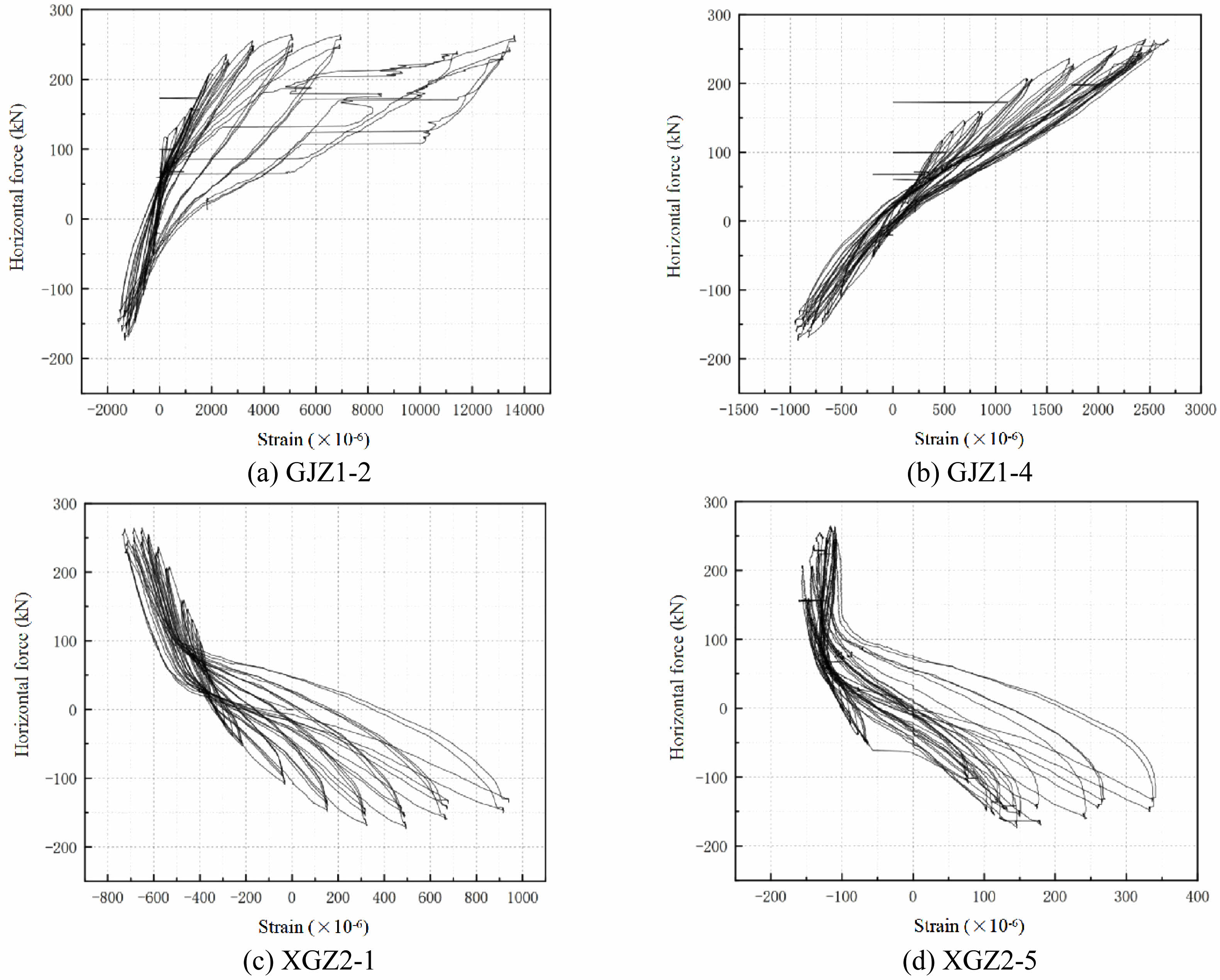
Load-strain curves of partial column, beam reinforcement and section steel in column are presented in Fig. 16. It is found that the strain response of the reinforcement and section steel in each member of the model increases gradually and the tensile deformation is larger under the action of positive and negative horizontal loads. The hysteresis curve of each measuring point is relatively full. This has been proven that steel has good energy dissipation capacity under horizontal loads, and its material properties are fully utilized.
|
Fig. 10 Apparent morphology of the static specimen. |
|
Fig. 11 Load-displacement curve under static loading. |
|
Fig. 12 Load-strain curves at different parts under static loading. |
|
Fig. 13 Apparent morphology of the quasi-static specimen. |
|
Fig. 14 Load-displacement hysteresis curve (DJZ2). |
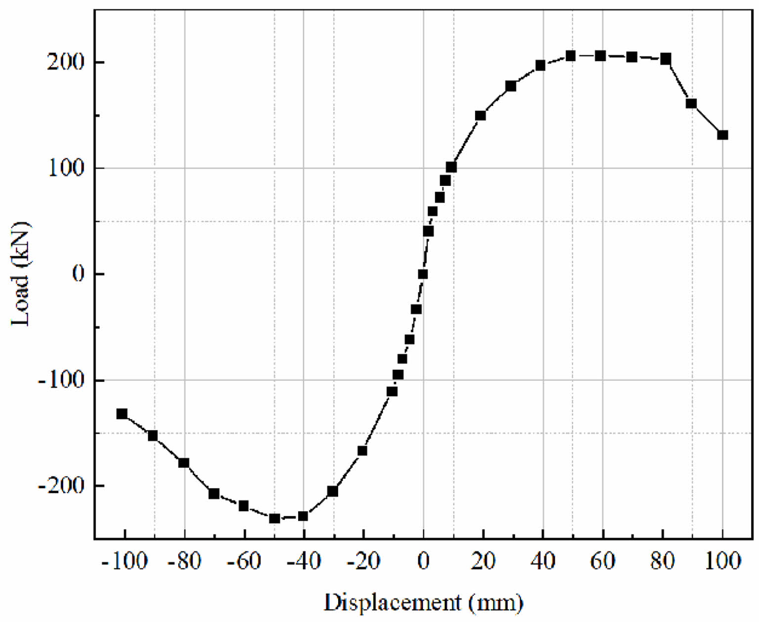
|
Fig. 15 Load-displacement skeleton curve (DJZ2). |
|
Fig. 16 Load-strain curves of partial column, beam reinforcement and section steel in column. |


Finite element software is used to establish static and quasi-static numerical models respectively for the actual lapping column transfer structure. It can be compared with the experimental results to verify the accuracy of the experimental results after calculation and analysis. Among them, the compressive strength of the cubic test specimen measured is 57 MPa. The calculated value of the actual axial compressive strength of concrete is 57×0.78=44.5 MPa. The compressive strength of concrete and elastic modulus are respectively taken as 44.5 MPa and 3600 MPa in the finite element analysis.
Simulation and Analysis of Static Characteristic
The C3D8R solid element form and plastic damage (CDP) constitutive model are used for refined finite element modeling of concrete. T3D2 truss element form and ideal elastoplastic model are used for refined finite element modeling of steel bars. The solid element form and ideal elastoplastic model are used for fine finite element modeling of section steel, with a yield strength of 390 MPa. The embedded interaction is adopted for both the section steel, steel bars and concrete. The relative slip between the concrete and the steel bar framework as well as the section steel is not considered.
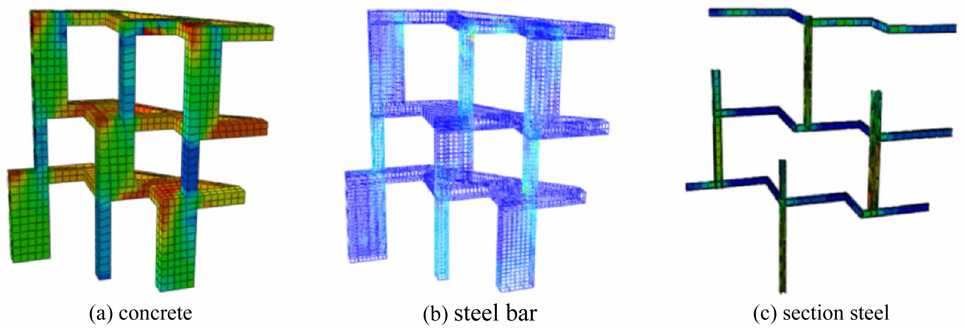
The finite element stress cloud map of lapping column is shown when static loading reached 1.2 times the design load value in Fig. 17. The results show that the maximum tensile stress in the concrete is 2.9 MPa, and the maximum compressive stress is 11 MPa. Specimen is at a relatively low stress level, and the specimens have not been damaged with high safety. The stress levels of the vast majority of steel bars are less than 100 MPa, and the structural safety margin is relatively high. Additionally, the stress of some steel bars at the junction of some small columns and large columns is relatively high (150 MPa). This is because this location is relatively close to the loading point. The calculation results of section steel are similar to those of steel bars. It can be considered that both steel bar and section steel have good mechanical properties.
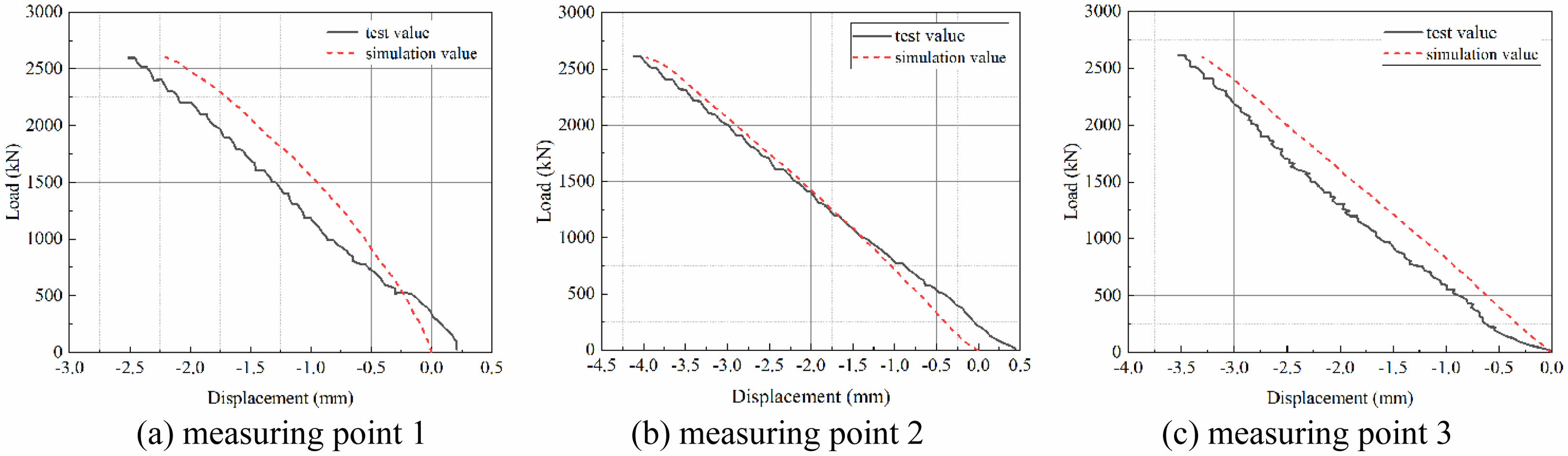
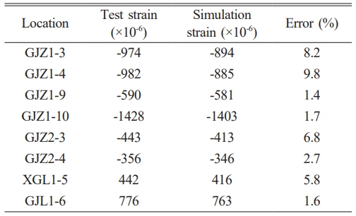
The comparison results of load displacement test values and simulation values at each measurement point are presented in Fig. 18. The maximum displacements generated by the simulations for the first, second, and third floors are -2.2 mm, -4.0 mm, and -3.3 mm, with errors compared to the experimental values being 12%, 2.4%, and 5.7%, respectively. It can be seen that the experimental values and the simulated values have a high degree of agreement. The maximum strain of different parts under 1.2 times the design load conditions is shown in Table 6. The maximum error between the experiment and simulation is 9.8%. In addition, the simulation results also indicate that neither the steel bar nor the section steel reached the yield strain (0.2%). It demonstrates that the scale model remains in an elastic state under maximum load. Based on this, it can be determined that the static performance of the original structure meets the design requirements.
Simulation and Analysis of Quasi-Static Characteristic
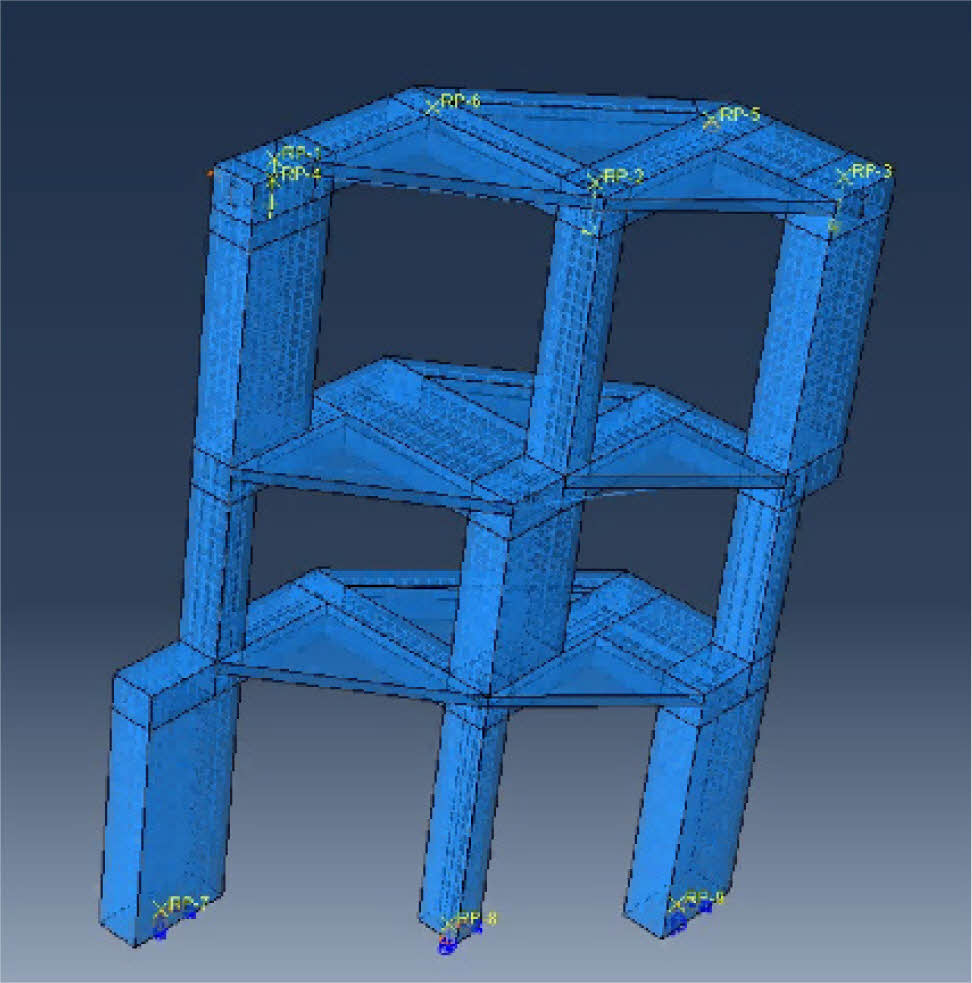
The solid element form and CDP constitutive model are used for refined finite element modeling of concrete. The steel bar is modeled as truss elements, and the constitutive model is an ideal elastoplastic model with a yield strength of 400 MPa. The post yield modulus is taken as 0.01 times the elastic modulus, and the ultimate strength is taken as 600 MPa. The section steel is modeled as shell element, and the constitutive model is a double kink linear kinematic hardening model with a yield strength of 400 MPa. The embedded interaction is adopted between the section steel, steel bar and concrete, and the bond slip is not considered. The refined finite element model is shown in Fig. 19.
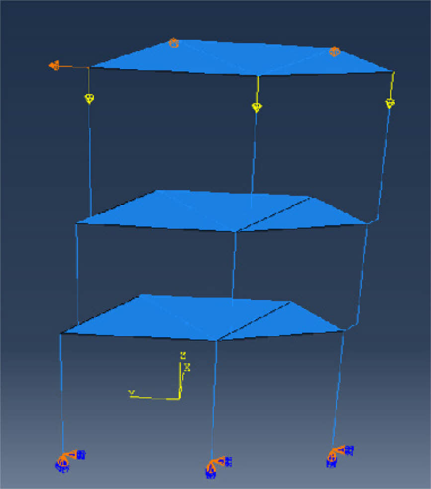
The concrete, steel section, and steel bar of beams and columns adopt beam elements with common nodes when establishing the fiber beam finite element model. A box section with an area equal to that of the steel bar is used to simulate the steel reinforcement. The tensile compressive concrete constitutive model (UConcrete02) of PQ-fiber plugin is used for concrete. The Clough model (USteel02) considering the degradation of bearing capacity of PQ-fiber plugin is used for the adoption of section steel and bar steel. The fiber beam finite element model is shown in Fig. 20.
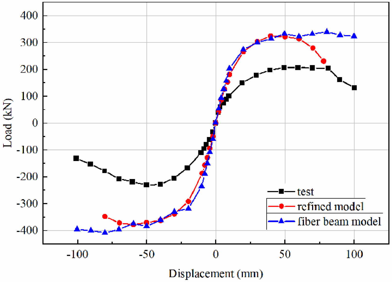
The load-displacement skeleton curves of two models can be obtained separately after calculation, and they were compared with the measured results of quasi-static test (Fig. 21). It can be shown that due to factors such as actual parameter errors, model construction errors, and large dispersion of concrete materials, there is a certain deviation between the finite element analysis results and the test measured data. However, it can still be seen that the lapping column transfer structure has excellent energy dissipation capacity and seismic performance.
|
Fig. 17 Finite element stress cloud map of lapping column. |
|
Fig. 18 Comparison of load-displacement curves. |
|
Fig. 19 Refined finite element model. |
|
Fig. 20 Fiber beam finite element model. |
|
Fig. 21 Comparison of load-displacement skeleton curve results. |
Relying on the characteristics of the mountain shaped retreating terrace style lapping column transfer structure in a certain museum in Hangzhou, one of the three-layer and three-bay lapping column was taken as the main research object. Static and quasi-static tests were carried out respectively on 1:5 scale model specimens, and the static and quasi-static characteristics of the lapping column transfer structure were analyzed. Furthermore, finite element software was utilized to conduct a simulated comparative analysis. The following conclusions were mainly drawn.
(1) It was found that when three column tops were uniformly loaded to 1.2 times the design load by conducting static tests on a 1:5 scale model, no obvious concrete cracks were observed on the surface of the specimen. The displacement varied linearly with the load, and neither the steel bars nor the section steel reached the yield strain of 0.2%.
(2) The static load mechanical performance of the retreating terrace style overlapping column transfer structure was further verified through finite element analysis. the maximum displacement and strain errors were respectively 12% and 9.8% by comparing with the experimental data. The simulation results also were showed that neither the steel bar nor the section steel reached the yield strain (0.2%). It was demonstrated that the scale model remained in the elastic state under the maximum load. It was determined that the static performance of the original structure met the design requirements.
(3) The 1:5 scale model quasi-static test study was conducted. The load displacement hysteresis curve and skeleton curve of the lapping column transfer structure were relatively full under horizontal reciprocating loads. The transfer structure had been proven to have good energy dissipation capacity.
(4) The maximum inter story displacement angle corresponding to the horizontal ultimate load of the scale model was 1/28 (> 1/50). And it could still bear the predetermined vertical load until the end of the loading. The lapping column transfer structure has been further proven to have good collapse resistance and seismic performance.
The datasets used and analyzed during the current study are available from the corresponding author on reasonable request.
The authors declared no potential conflicts of interest with respect to the research, author-ship, and publication of this article.
The authors received no financial support for the research.
- 1. A. Saxena, A. Abraham, and B.I. Sang, J. Ceram. Process. Res. 25[6] (2024) 1122-1141.
-

- 2. Z.J. Zhu, S.L. Zhao, and R.B. He, Build. Struct. 42[6] (2012) 77-81.
- 3. F. Lin, W.B. Sun, and P.F. Zhao, Build. Struct. 44[15] (2014) 45-50.
- 4. L. Gu and X.Y. Fu, Build. Struct. 33[12] (2003) 13-16.
- 5. X.Y. Fu, K.E. Lei, X.B. Yang, C.H. Chen, L. Gu, and J. Y. Jia, Build. Struct. 33[12] (2003) 8-12.
- 6. P.F. Xu, X.Y. Fu, N.N. Geng, C.K. Wang, and C.Z. Xiao, Build. Struct. 33[12] (2003) 3-7.
- 7. X.Y. Quan, Z.J. Kong, and F. Deng, Build. Struct. 36[2] (2006) 25-28.
- 8. C. Shen, X.Q. Zhao, L. Xia, and J. Sun, Build. Struct. 41 (2011) 361-366.
- 9. P.G. Tian, K. Wang, J.H. Niu, Z.X. Xie, K.N. Liu, and Z.S. Wang. J. Ceram. Process. Res. 25[4] (2024) 704-716.
-
- 10. X.L. Lv, C.Q. Zhang, and J.B. Li, J. Build. Struct. 32[6] (2011) 10-17.
- 11. J. Huang, S.C. Wang, and Z.X. Wang, Build. Struct. 46[S1] (2016) 122-127.
- 12. S.N. Fu and J.H. Xu. Build. Struct. 46[24] (2016) 17-21.
- 13. L.W. Yan, B.B. He, R.J. Tao, and F.D. Ma, Build. Struct. 48[21] (2018) 48-51.
- 14. H.J. Xue and Z.B. Zhao, Build. Struct. 50[S1] (2020) 103-107.
- 15. T.W. Song, Y. Feng, J.B. He, K.J. Xiao, Z.W. Feng, Y.J. Li, Z.X. Liao, and L.W. Xu, Build. Struct. 50[19] (2020) 56-61.
- 16. D.C. Li, Build. Struct. 53[9] (2023) 53-58.
- 17. Y. Ding, Y. Zhao, L.Y. Huang, and X. Zhang, Guangdong Archit. Civ. Eng. 30[9] (2023) 50-53.
 This Article
-
2025; 26(5): 852-863
Published on Oct 31, 2025
- 10.36410/jcpr.2025.26.5.852
- Received on May 29, 2025
- Revised on Jul 7, 2025
- Accepted on Aug 7, 2025
Services
- Abstract
introduction
project overview
scale model test
model test results analysis
finite element simulation and analysis of lapping column
conclusion
- Data sharing agreement
- Declaration of Interest
- Funding
- References
- Full Text PDF
Shared
Correspondence to
- Xiaoxia Zhao
-
China Construction Fourth Engineering Bureau Co., Ltd. Guangzhou 510000, Guangdong, China
Tel : +86 19822660870 - E-mail: 19822660870@163.com
Clean-Energy Research Institute(CRI), Hanyang University, 222, Wangsimni-ro, Seongdong-gu, Seoul, 04763, Korea
E-mail: jcpr@hanyang.ac.kr