


- Study of melting properties of phase change materials at different inclination angles and heating boundaries
Peng Hu*
Marine Engineering College, Dalian Maritime University, Dalian 116026, China
This article is an open access article distributed under the terms of the Creative Commons Attribution Non-Commercial License (http://creativecommons.org/licenses/by-nc/4.0) which permits unrestricted non-commercial use, distribution, and reproduction in any medium, provided the original work is properly cited.
Phase change thermal storage devices can effectively solve the shortcomings of solar energy such as intermittency and uncertainty, and realize the efficient use of renewable energy. However, the low thermal conductivity of phase change materials makes it a research priority to increase the melting rate of heat storage units. In this paper, the melting performance enhancement of the phase change thermal storage device is investigated. A numerical model is constructed for the phase change process of the device at different inclination angles and heating boundaries, and parameters such as the complete melting time, the melting fraction, the phase interface and the temperature fields are discussed. The results show that the phase change heat storage rate is optimal at 90° inclination, which reduces the complete melting time by 14.05% compared to 0° inclination. In addition, the increase of inclination angle not only increases the melting rate, but also reduces the area of refractory region and improves the melting uniformity.
Keywords: Phase change materials, Melting properties, Inclination, Heat source, Numerical simulation.
Solar energy has been the cornerstone for life to thrive on earth since ancient times. It offers a constant energy source for the growth of everything [1-3]. The global demand for energy is growing, and fossil fuel resources are under increasing strain. Besides, there are serious challenges like environmental pollution and climate change. So, developing and utilizing solar energy is becoming more and more crucial [4, 5]. But, it is difficult to popularize and apply solar energy widely. Its inherent characteristics of being dispersed and unstable make it tough to collect and convert solar energy efficiently and stably [6-8]. Phase change materials (PCMs) have excellent potential in using solar energy [9, 10]. PCMs can absorb solar energy and turn it into thermal energy. They can store a large amount of energy during the phase change process. In this way, it solves the challenges brought by the intermittent and unstable nature [11-13].
Some research has been done on PCMs regarding solar thermal utilization too. Poonia [14] built a solar dryer that includes PCM technology. This actually provided a new way to handle the drying process of other foodstuffs by using sunlight after sun drying. Another thing worth mentioning, Hansen [15] combined an inclined solar still with a conventional one. As a result, there was an overall increase in the daily distillation yield. The experimental results revealed that a finned absorber along with a PCM can boost the productivity of the system significantly. Kabeel [16] managed to enhance the production of distilled water during the daytime by installing closed copper tubes and filling them with PCM in a tubular solar still. And it turned out that using PCM-filled copper tubes is the top choice to make tubular solar stills work better. Li and Zhang [17] designed a PVT-PCM collector system together. This system mixes photovoltaic (PV) technology and thermal energy harvesting while making use of PCMs. Their aim was to meet the building's thermal energy requirements throughout the year and also to really improve the overall efficiency with actually practical measures.
Ashouri and Hakkaki-Fard [18] created a simulation model with the help of the FVM, which provides an insight into the effect of fin absorber and concentrating material on the efficiency of the building system. The data from their study showed that in a design without fins, increasing the quality of the PCM resulted in a reduction in ventilation, but not a significant improvement in ventilation hours. Yu [19] has developed a novel pyroelectric energy harvesting system, which employs a PEG and 1-TD composite PCM. It can effectively harvest energy under different solar irradiations and ensure stable power output. Hatamleh and Abu-Hamdeh [20] developed an efficient thermal insulation exterior wall by integrating intelligent technology with PCM (n-heptane). In parallel, they utilized molecular dynamics simulation techniques to explore the thermal characteristics of glass within a PCM environment. The findings indicate that the incorporation of PCM notably enhances the thermal efficiency of glass, augments its insulating capabilities, and diminishes energy consumption expenses.
Despite the fact that PCMs have demonstrated excellent performance, the way they are installed remains a key element that cannot be ignored when building large-scale thermal energy storage systems in solar utilization [21, 22]. To maximise the thermal efficiency, the thermal storage performance of phase change devices at different inclination angles has become an urgent topic for in-depth research in solar system [23, 24]. Some scholars have paid great attention to this and conducted experiments and simulations for this. Abdulmunem [25] used numerical and experimental analyses to investigate how the tilt angle affects the parameters of the charging behaviour of a PCM in a rectangular container behind a photovoltaic cell, and explored its application in temperature control of photovoltaic cells. The experimental results demonstrate that increasing the inclination angle of the PV/PCM system from 0° to 90° progressively shortens the melting duration of the phase change material (PCM). Correspondingly, the overall temperature of the photovoltaic (PV) cells decreases, with the temperature reduction amplitude expanding from 0.4% to 12% across the angular range. Notably, the PCM exhibits minimal cooling efficacy at smaller inclination angles, indicating inefficient thermal regulation under near-horizontal configurations. Avci [26] conducted an analysis to investigate the impact of inclination angle on the thermal efficiency of flat plate heat sinks, both in the absence and presence of PCM, via experimental comparisons. The study reveals that the peak temperatures of PCM-integrated systems remain significantly lower than those of non-PCM systems across all inclination angles. Furthermore, increased inclination angles in PCM-enhanced configurations prolong the retention time of elevated-temperature states within critical operational periods. Yazici and Avci [27] investigated how the number of fins and the tilt angle work together on the thermal performance of PCM based longitudinal plate fin heat sinks. The results indicate that both factors exerted significant influences on the formation of convective mechanisms, heat transfer efficiency, and total operational duration within the liquid PCM domain, with the configuration combining a 60° inclination angle and triple-fin heat sinks demonstrating the most extended operational duration in performance metrics. Sorour et al. [28] co-developed a numerical analysis and experimental of the charging process of PCMs inside a PCTES with different tilt angles. The experiment found that the thickness of PCM was sufficient, the inclination Angle had a significant impact on the melting of PCM, natural convection promoted the melting, and the 45° inclination Angle was the best. When the PCM is thin, placing it horizontally can minimize the total melting time. Castro-Vizcaino et al. [29] employed an experimental and simulation-based approach to conduct a detailed study on the dynamic behaviors of PCM heat storage capsules during freezing and melting processes. They also focused on analyzing the influence of inclination angles on the phase change dynamics. The experimental and simulation results jointly indicate that the freezing time does not increase or decrease linearly with the change of the inclination angle, but rather presents a complex nonlinear pattern, among which the freezing time is the largest when the inclination Angle is 45°. The simulation data also show that the loose fillers inside the capsules not only slow down the freezing rate but also enhance the effect of the inclination angle on the freezing speed. Yoladi et al. [30] conducted experiments on the thermal properties of PCMs through small channels within a cylindrical shell. They analyzed the thermal effects of the inlet temperature, depth, duration and inclination angle during the process of adding the heat transfer fluid. Through the application of response surface methodology, it was found that the inclination angle has influences on solid-liquid interface expansion and heat transfer rate. Among them, at the inlet temperature of 55 °C, the maximum temperature change at a depth of 3-6 mm and a 0° Angle is 28.4%. For a depth of 6-9 mm, the 0° Angle is 7.51%. The depth of 9-12 mm and the 90° Angle reach 30.5%. In conclusion, incre asing the inclination Angle can generally improve the heat dissipation performance containing PCM, such as promoting the melting of PCM, reducing the battery temperature, extending the period of high temperature, optimizing operation and heat exchange. The melting is optimal and the capsule freezing time is the longest when the PCM thickness is at a 45° inclination Angle. The heat exchange temperature change is the greatest at a specific depth of the cylindrical shell at a 90° inclination Angle. However, different systems have different effects on the better inclination Angle and performance improvement, and further research is needed.
Meanwhile, the numerical simulation study of phase change heat storage also has high accuracy and has been well experimentally verified. Mills et al. [31] used a combination of experimental tests and numerical simulations to investigate the cooling characteristics of tree fins submerged in a bio-based phase change material. The experimental results indicate that the bottom heating method has the lowest heater temperature; the numerical results also show that the bottom heating helps to stabilise the surface temperature of the heater at a minimum due to the natural convection effect, which is consistent with the experimental results. Sonker et al. [32] focus on parametric analysis of solar desalination system to investigate the effect of PCM and nanoparticles on the efficiency of monoclinic device. Simulations show that the use of phase change materials and nanoparticles can increase the solar static productivity, in agreement with experimental results. Dora et al. [33] added the PCM obtained by impregnating and peeling vermiculite with decanoic acid and anhydrous ethanol to the foam concrete, thereby improving the thermal performance of the building. The experimental results show that PNC-5% (with 5% nano-silica) has the best overall performance with excellent mechanical and thermal parameters, nano-silica optimises the structure, enhances the heat resistance and has a lower mass loss than the normal PCM mixture. Where the thermal efficiency of PCM foam concrete was verified using COMSOL Multiphysics, which was consistent with the experimental findings. Belwadi and Akula [34] employed topological optimization to design the TCE structure for the PCM-based cylindrical lithium-ion BTMS. The experimental results show that the optimised structure reduces the cell temperature by 4.9 °C, the PCM melting and temperature distribution are more uniform, and the thermal performance is significantly better than that of the conventional fins. Transient numerical analysis was also carried out using COMSOL to compare the topology optimised design with three benchmark designs, and the results are consistent with the experimental findings.
Currently, PCMs occupy an important position in solar energy utilization, but their cavity melting performance under different mounting inclinations still needs to be explored in depth, and the evaluation indexes need to be further improved. Therefore, we constructed a numerical model covering the charging of PCMs at various inclinations such as 0°, 30°, 60° and 90° under different heat sources, aiming at selecting the optimal installation inclination by comprehensively evaluating and analyzing the complete melting time, the melting rate, the amount of heat storage, the temperature, the velocity, and the evolution of the phase interface. The establishment of this model not only enriches the assessment indicators, but also provides a more accurate and reliable reference basis for the actual solar thermal utilization process.
Problem Description
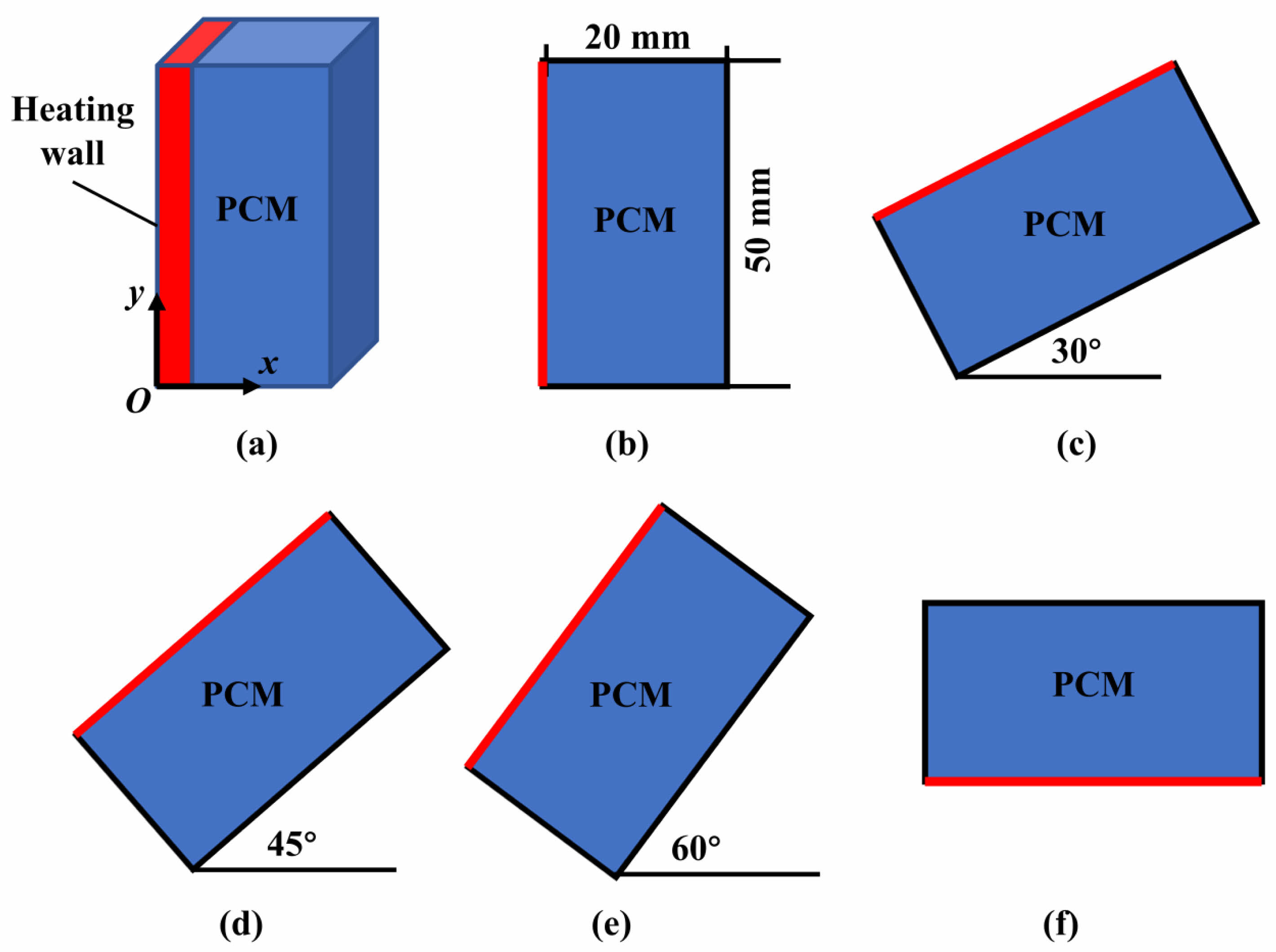
This paper primarily focuses on the investigation of a square cavity-shaped phase change heat storage device, which finds application in building energy systems. By harnessing the phase change process, this device efficiently captures and stores solar energy. Fig. 1 illustrates the physical configuration of the PCTES device, alongside the corresponding numerical models for various inclination angles. Considering the physical characteristics of the heat storage unit, the numerical model has been simplified to a two-dimensional representation for computational efficiency. During the construction of the numerical simulation framework, the computational domain was reduced to a two-dimensional (2D) configuration, thereby optimizing computational efficiency while maintaining adequate predictive fidelity for the model.
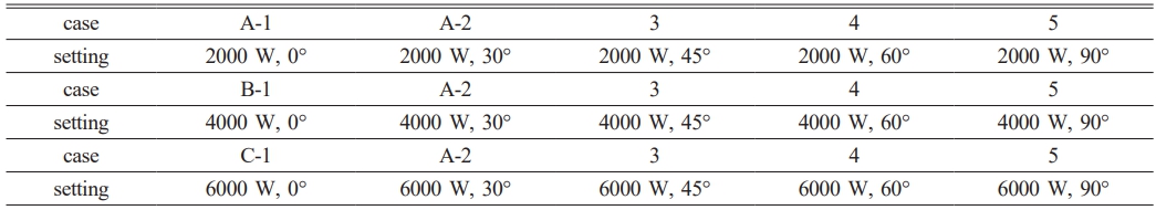
The heat storage unit has a heating surface and a phase change heat storage cavity. The cavity is 100 mm long and 50 mm wide. The heating surface is on its left side. Wax has been chosen as the PCM for the heat storage process. These properties are listed in Table 1. The main aim of this study is to look into the melting process inside the heat storage device. This will be done under different heating boundary conditions and inclination angles. To achieve this, a bunch of numerical simulations have been carried out. The details of these simulations are summed up in Table 2.
Main assumption
In this paper, in order to simplify the calculation, we solve the numerical model by using COMSOL 6.2, the following key assumptions were made for the simulation:
(1) Paraffin wax is regarded as homogeneous, and the property parameters are set to be constant and not to vary with temperature. Since the research is conducted in a non-high-temperature and non-high-pressure environment, the actual changes in physical properties are relatively small. Therefore, the influence of this assumption on the simulation results can also be controlled within an acceptable range.
(2) The volume change during charging process of paraffin wax is ignored. Since the research focus lies in the heat transfer mechanism and temperature field distribution during the wax phase transition process, and the volume change during the wax phase transition is relatively small, the influence brought about by the volume change is ignored.
(3) The phenomenon of overheating or overcooling is regarded as non-existent in the simulation. Due to the high purity of paraffin wax, the nucleation conditions can be easily controlled and the phenomena of overheating and overcooling can be neglected.
Mathematical model
Based on the main assumptions, this paper solves the charging process through three equations. The main governing equations are:
Continuity Equation:
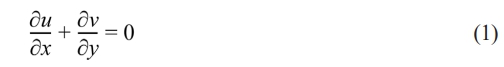
Momentum equation:
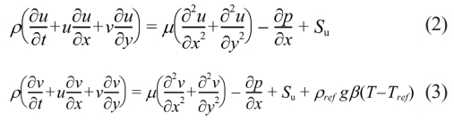
Energy equation:

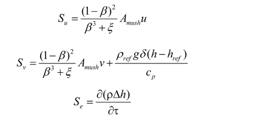
Where h denotes the latent heat of phase transition, λ represents the thermal conductivity, p indicates the pressure, ρ stands for the density, and μ indicates the dynamic viscosity. Su and Sv represent the source terms of the momentum equation. Se indicates the source term of energy equation.
Source term:
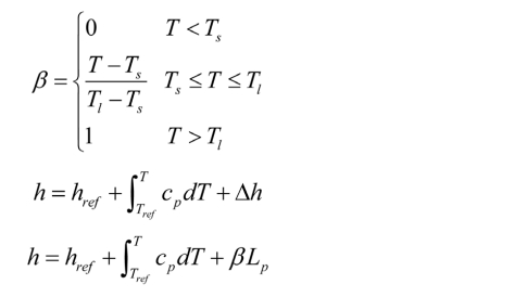
Liquid fraction:
Verification of Grid Independence and Independence
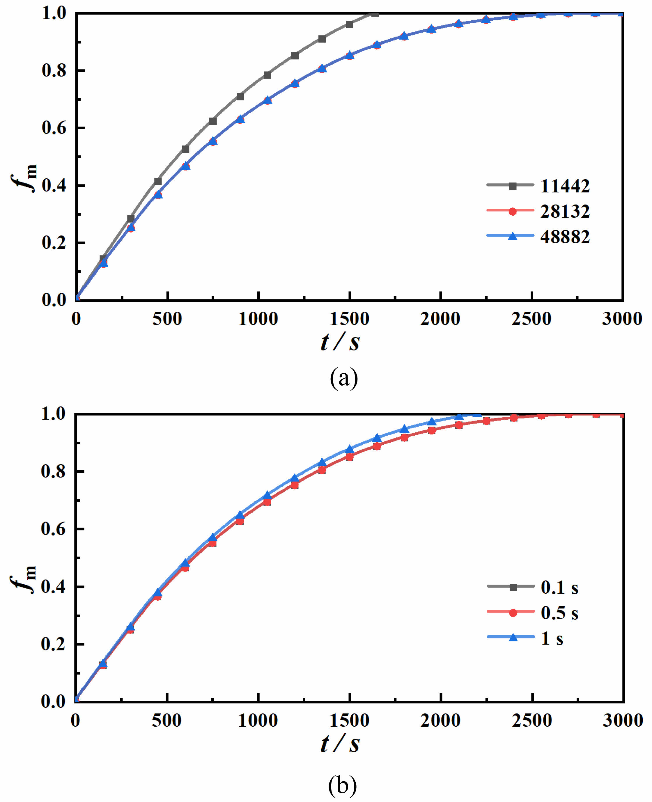
To ensure computational accuracy and resource efficiency, we systematically validated grid independence by analyzing Case B-1’s melt rate distributions across spatial resolutions of 11,442, 28,132, and 48,882 elements. The results demonstrated that increasing the grid count to 28,132 elements yielded deviations less than 1% compared to the 48,882-element reference (Fig. 2a). Notably, the 11,442-element mesh exhibited substantial discrepancies (>8% error), confirming its insufficient resolution for accurate predictions. Thus, 28,132 elements were selected as the optimal grid resolution to satisfy grid independence criteria. For time step independence validation, we evaluated 0.1 s, 0.5 s, and 1.0 s steps. The 0.5s time step demonstrated superior performance, achieving 98.7% energy conservation accuracy while reducing computational load. Based on these findings, we established 28,132 elements and 0.5s time steps as the computational framework, balancing precision and efficiency for subsequent simulations. When determining the grid size and time step size, the limitations of computing resources and model accuracy were fully considered. A higher number of grids and a smaller time step size can improve accuracy, but they will increase the computational burden. After multiple tests, the parameter combination that could not only meet the accuracy requirements but also take into account the computational efficiency was finally selected. Achieve dual excellence in accuracy and efficiency.
Experimental verification
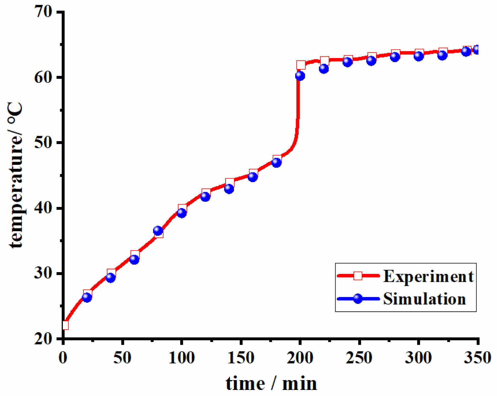
By comparing the experimental conditions of the square cavity model of Zhang et al. [35], a numerical model was established and kept consistent with its boundary conditions and experiments. Meanwhile, the melting process temperatures at the measurement point 12 mm were selected for comparison, and the comparison results are shown in Fig. 3. It can be found that the trends of the simulation and experimental results are consistent, and the maximum error is less than 5%. Based on the verification results, the accuracy of the numerical model was verified.
|
Fig. 1 Physical model and numerical model of the PCTES unit. |
|
Fig. 2 Grid independence and time step independence verification. |
|
Fig. 3 Simulation verification |

Complete melting time
Figure 3 presents the complete melting times of phase change thermal energy storage (PCTES) units with various inclination angles under multiple heating surfaces. Specifically, Fig. 3(a) illustrates the complete melting times of different PCTES devices under a 2000 W heating surface. Among them, Case A-1 exhibits a complete melting time of 4370 s. As shown in the figure, with an increase in inclination angle, the melting rate also increases. Compared to Case A-1, Cases A-2, A-3, A-4, and A-5 exhibit reductions in complete melting time by 4.11%, 6.87%, 8.69%, and 14.41%, respectively. At a 90° inclination angle, the complete melting time is significantly shortened, making Case A-5 the optimal heat transfer configuration.
In Fig. 3(b), Case B-1 represents a thermal storage device with a 0° inclination angle under a 4000 W heating surface, with a complete melting time of 2840 seconds. Similarly, the shortest complete phase change time occurs at a 90° inclination angle, which is only 2480 seconds, representing a 12.67% reduction compared to Case B-1. Additionally, the melting rates of the PCTES devices with inclination angles of 30°, 45°, and 60° compared to the 90° inclination angle also increase, with complete melting times shortened by 2.81%, 6.33%, and 7.39%, respectively.
Figure 3(c) displays the complete melting times of the devices under a 6000 W heating surface. The optimal configuration is Case C-5, which exhibits a 14.05% reduction in complete melting time compared to Case C-1. Therefore, the three different heating surfaces exhibit the same trend: the complete melting time of thermal storage devices with a 90° inclination angle is shortened by more than 10% compared to those with a 0° inclination angle.
By synthesizing the complete thermal storage times under different heating surfaces, it can be observed that as the heat flux of the thermal storage surface increases, the complete melting time decreases accordingly. Specifically, Case C-5 exhibits reductions in complete melting time by 90.82% and 26.53% compared to Cases B-5 and A-5, respectively. However, as the heat flux gradually increases, the reduction in thermal storage time diminishes. For instance, the complete phase change time of Case C-5 under a 6000 W heating surface is only 580 seconds shorter than that of Case B-5 under a 4000 W heating surface. Therefore, after the heat flux of the heating surface increases to a certain extent, the benefits it brings become limited. Consequently, based on the actual required complete phase change time, a reasonable selection can be made for resource optimization.
Fraction of melting
Figure 4 illustrates the variation of melting fraction for different inclination under a heating surface of 4000 W. Overall, as depicted in the figure, the melting fraction increases with time, exhibiting a faster rate in the early stages and a slower rate in the later stages. The entire melting process can be divided into three distinct phases for detailed analysis. In the initial melting phase (approximately 0 to 1000 s), the melting rate rapidly ascends. This is primarily attributed to the proximity of the paraffin to the heating surface, placing it in a state of rapid melting. During this phase, thermal conduction dominates the heat transfer process, leading to rapid heat accumulation within the paraffin. Notably, although the sensible heat increase rate is slightly faster in high-inclination thermal storage units, resulting in a marginally lower melting rate compared to low-inclination units, the overall difference remains insignificant. At the end of this phase, the melting rate disparities among different inclination angles are minimal.
Transitioning into the middle melting phase (1000 to 2000 s), the melting rate gradually decreases. This decrement stems from the near-complete melting of paraffin wax adjacent to the heating surface. Due to the paraffin's inherently low thermal conductivity, heat transfer to regions farther from the heating surface becomes increasingly challenging. Concurrently, a significant
temperature gradient develops within the thermal storage unit, enhancing the influence of natural convection on heat transfer effectiveness. Consequently, the melting performance of units with different inclination angles begins to diverge, with higher inclination angles benefiting from more intense natural convection and thus exhibiting higher melting rates than low-inclination units from this point onward. Finally, in the late melting period (after 2000 s), the melting speed is close to zero, which indicates that the melting process is near completion. At this stage, refractory areas are formed at the bottom of the unit, because they are far away from the heating surface, and at the same time, the natural convection effect is weak, which greatly increases the full melting time. It is noteworthy that the 90-degree inclined configuration exhibits a reduced refractory area compared to other devices, suggesting that an increase in inclination favors an enhancement in the melting rate. In conclusion, the study examines the dynamic interplay between heat conduction and natural convection mechanisms during the melting process by analyzing the heat transfer characteristics of PCM at varying inclination angles. Therefore, during the initial melting stage, the inclination Angle has a relatively small influence on the melting rate because the thermal conductivity of solid PCM is much lower than that of liquid, and heat transfer mainly relies on contact heat conduction. In the later stage, the inclination angle directly affects the melting rate by changing the natural convection path.
|
Fig. 4 Complete melting time of PCTES device under different inclination angles: (a) 2000 W; (b) 4000 W; (c) 6000 W. |
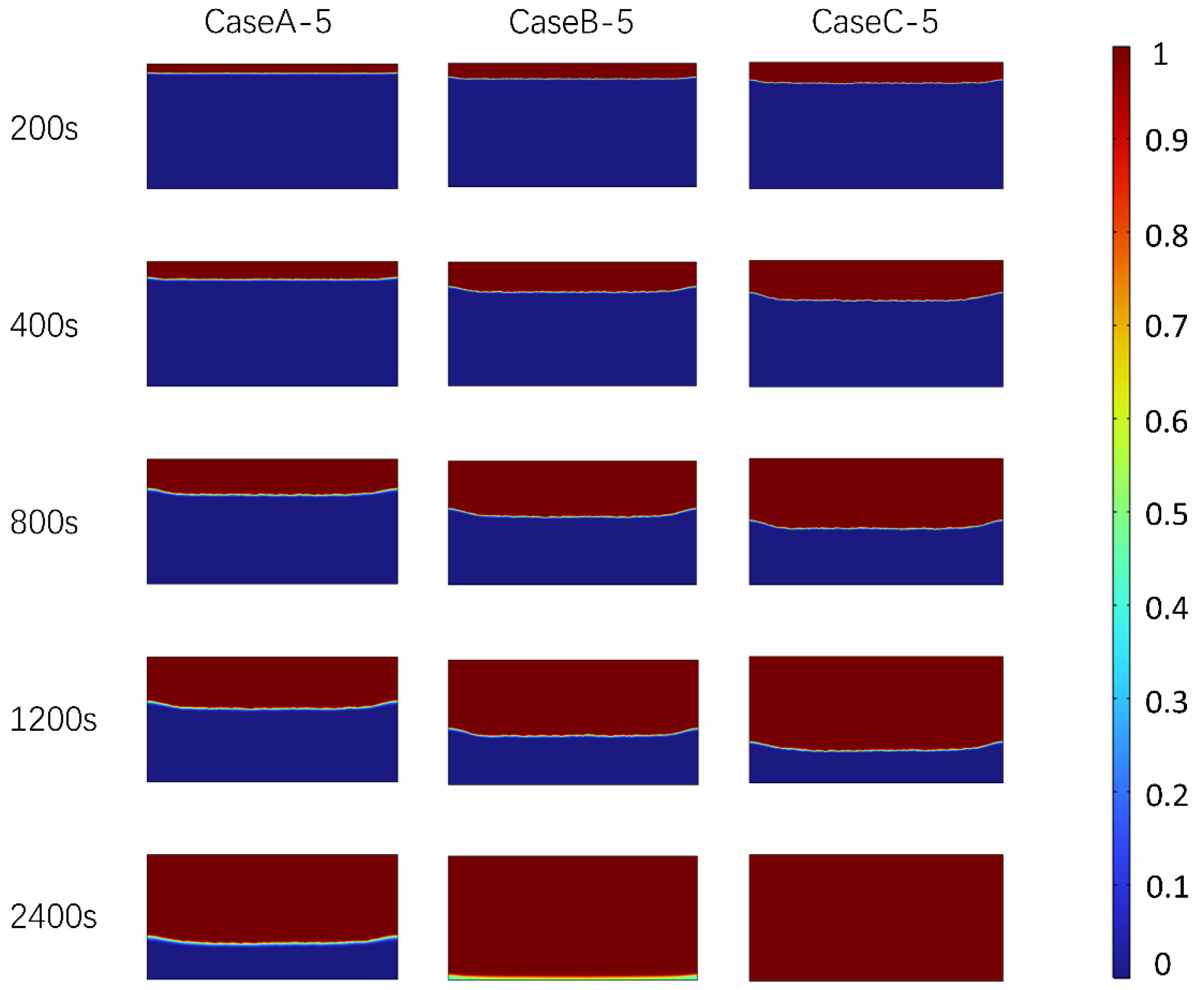
To visually illustrate the differences in melting processes among various cases, Figs. 5 and 6 present the melting distribution and temperature field distribution, respectively, of PCTES units with different inclination angles under a 4000W heating surface. Figure 5 delineates the melting distribution at 0°, 30°, 45°, 60°, and 90° inclination angles at specific time intervals of 200s, 400s, 800s, 1200s, and 2400s. In this representation, red denotes the liquid paraffin phase, while blue represents the solid paraffin phase. Overall, as time progresses, the melting process advances in all PCTES units. Specifically, in Case B-1, the phase interface exhibits a funnel-like shape, with faster melting occurring at the top and slower melting at the bottom, resulting in a steep phase interface gradient. As the melting process continues, the upper region fully melts, leaving a refractory area at the bottom. Compared to Case B-1, Cases B-2, B-3, B-4, and B-5 exhibit increased melting rates at the top as the inclination angle increases, leading to a gradual reduction in the phase interface slope and a corresponding decrease in the size of the refractory area. In Case B-5, the melting is relatively uniform, with almost no refractory area present. At 2400s, the refractory area, if any, appears triangular and decreases in size as the inclination angle decreases. This is attributed to the enhanced natural convection effect with increasing inclination, which increases the contact area between the hot and cold phases, improving the overall efficiency of the PCTES unit. In summary, in the high-inclination device, the direction of gravity is perpendicular to the heating surface. The natural convection is mainly vertical upward flow. The liquid PCM forms regular laminar vortices near the heating surface, enhancing the advancement of the melting front at the top. The low-inclination convection path extends horizontally, and the liquid PCM accumulates at the top of the heating surface to form a thermal stratification. The top melts too quickly while the bottom melts lagging behind, resulting in a prolonged melting time.
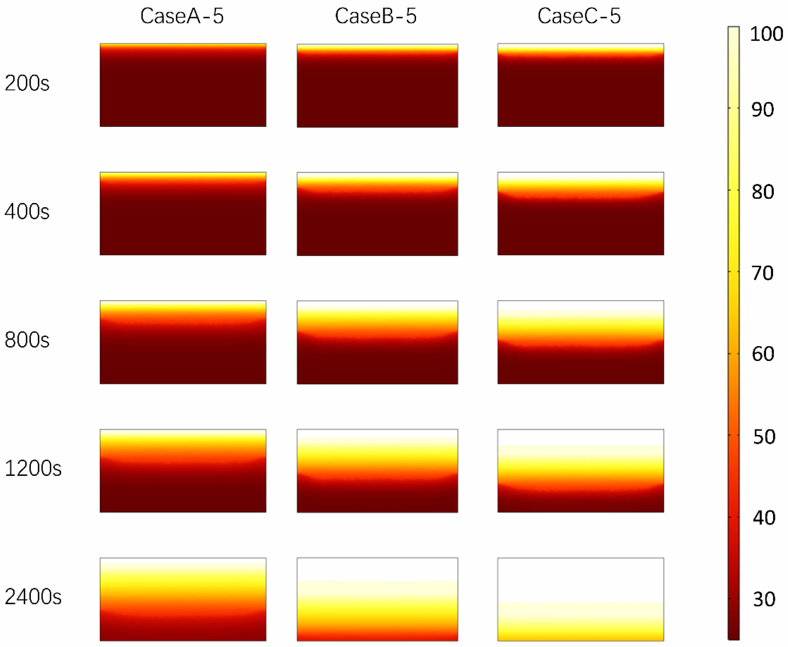
Figure 6 displays the temperature field variations at different inclination angles. Similar to the phase interface distribution, the temperature gradient distribution also exhibits a funnel-like shape. Notably, a clear temperature stratification is observed at the phase interface due to the temperature difference between liquid and solid paraffin, which drives natural convection. As the inclination angle increases, the contact area between solid and liquid paraffin in the gravitational direction increases, further enhancing convective heat transfer and resulting in faster temperature rise compared to PCTES units with smaller inclination angles. Additionally, as process progresses, the overall temperature of the thermal storage unit rises, causing the temperature interface to become increasingly blurred. This leads to a further intensification of overall natural convection, and the difference in melting rates among units with different inclination angles becomes increasingly significant. Finally, it is observed that as the inclination angle increases, the temperature field uniformity also gradually improves. Therefore, the inclination angle not only enhances the melting efficiency of the PCTES unit but also improves temperature uniformity. In the text, the smooth heating surface can significantly enhance heat conduction compared to fins or metal foams, and at this time, the influence of the inclination Angle on the melting rate is weakened. Subsequently, further research can be conducted on the influence of various configurations and different inclination angles.
Figures 7 and 8 comprehensively exhibit the distribution characteristics and temperature field evolution of PCTES units during the melting process under multiple heating powers. Specifically, Fig. 7 details the melting distribution within the PCTES units at specific time points (200 s, 400 s, 800 s, 1200 s, and 2400 s) for heating powers of 2000 W, 4000 W, and 6000 W. Across these heating scenarios, it is clearly observable that the phase interface remains almost parallel to the heating boundary and gradually shifts downward over time. Notably, when comparing the melting interfaces at 2000 W, 4000 W, and 6000 W, the melting rate under 2000 W conditions is slower, with the melting interface positioned lower at the same time points compared to the other two cases. In the initial stages of the melting process, the differences in melting distribution among different heating powers are not significant, primarily due to the small temperature difference within the unit, which results in relatively weak natural convection effects and makes thermal conduction the dominant heat transfer mechanism. However, as the melting process progresses, the overall temperature difference within the PCTES unit gradually increases, enhancing the natural convection effect and leading to increasingly pronounced differences in the distribution of the phase interface front. Specifically, the higher the heat flux on the heating surface, the faster the melting rate, a trend that becomes particularly evident in the later stages of melting.
Fig. 8 shows the temperature distribution of PCTES unit at the same heating power and time point. As shown in the figure, with the increase of heat flux, the temperature of PCTES unit rises faster, and the overall heating efficiency is improved. In addition, at 2400s, PCTES units at 6000 W heating power show higher temperature uniformity compared with 4000 W and 2000 W heating conditions. This shows that the heating surface with high heat flux can not only improve the heat storage efficiency, but also optimize the uniformity of the temperature field to a certain extent, thus improving the overall performance of the PCTES unit. In summary, the optimization of heating surface and inclination Angle can provide reference for the application of PCTES unit in practical engineering. Fig. 9
|
Fig. 5 The melting fraction of PCTES devices varying with time under different inclination angles. |
|
Fig. 6 Calculation of melting front distribution of PCTES unit at different inclination angles. |
|
Fig. 7 Calculation of temperature field distribution of PCTES unit at different inclination angles. |
|
Fig. 8 Calculation of melting front distribution of PCTES units under different heating surfaces. |
|
Fig. 9 Calculation of melting front distribution of PCTES units under different heating surfaces. |
This paper conducts a study on the melting performance of PCTES devices under different inclination angles and heating boundaries by constructing a numerical model. The main conclusions are as follows:
Under the three heating powers of 2000 W, 4000 W and 6000 W, the PCTES device with a 90° inclination Angle configuration has the shortest melting time, which is shortened by more than 10% compared with the 0° inclination angle.
The natural convection effect is significantly enhanced with the increase of the inclination angle, promoting the increase of the melting rate.
As the heating power increases from 2000 W to 6000 W, the melting time of the PCTES device decreases.
The melting front advancement is closely linked to the heating power. Higher heating power results in a more rapid melting process, with the melting front moving deeper into the PCM material compared to lower power settings.
The temperature profiles that increased heating power leads to a more uniform temperature distribution within the PCTES unit. This uniformity is crucial for efficient energy storage and retrieval.
In conclusion, high heating power can significantly shorten the melting time and improve temperature uniformity. However, in practical engineering applications, low power is accompanied by lower operating costs. Therefore, by comprehensively considering the win-win situation of economy and energy efficiency, it is reasonable to adopt a collaborative optimization scheme of lower power and optimized inclination Angle configuration. The 4000 W power heating and 90° inclination installation ensure the stability of heating and the economic operation, providing guiding significance for practical projects.
- 1. M.K.H. Rabaia, M.A. Abdelkareem, E.T. Sayed, K. Elsaid, K.-J. Chae, T. Wilberforce, and A.G. Olabi, Sci. Total Environ. 754 (2021) 141989.
- 2. K. Obaideen, M.N. AlMallahi, A.H. Alami, M. Ramadan, M.A. Abdelkareem, N. Shehata, and A.G. Olabi, Int. J. Thermofluids 12 (2021) 100123.
-

- 3. G. Li, M. Li, and R. Taylor, Appl. Therm. Eng. 209 (2022) 118285.
-
- 4. C.M.S. Kumar, S. Singh, and M.K. Gupta, Sustain. Energy Technol. Assess. 55 (2023) 102905.
-
- 5. G. Liu, J. Xu, and T. Chen, Phys. Rep. 981 (2022) 1-50.
-
- 6. I. Jebli, F.Z. Belouadha, and M.I. Kabbaj, Energy 224 (2021) 120109.
-
- 7. A. Sharif, M.S. Meo, M.A.F. Chowdhury, and K. Sohag, J. Clean. Prod. 292 (2021) 126028.
-
- 8. B. Fang, Z. Xing, D. Sun, Z. Li, and W. Zhou, Adv. Powder Mater. 1[2] (2022) 100021.
-
- 9. H. Mehling, M. Brutting, and T. Haussmann, J. Energy Storage 51 (2022) 104354.
-
- 10. J. Luo, D. Zou, and Y. Wang, Chem. Eng. J. 430 (2022) 132741.
-
- 11. R. Chaturvedi, A. Islam, and K. Sharma, Mater. Today Proc. 43 (2021) 293-297.
-
- 12. L. Wang, L. Guo, and J. Ren, Appl. Energy 321 (2022) 119345.
-
- 13. M. Carmona, A.P. Bastos, and J.D. Garcia, Renew. Energy 172 (2021) 680-696.
-
- 14. S. Poonia, A.K. Singh, and D. Jain, Cogent Eng. 5[1] (2018) 1507084.
-
- 15. R.S. Hansen, M.B.Q. Mary, and S.S. Subramanian, Mater. Today Proc. 62 (2022) 967-972.
-
- 16. A.E. Kabeel, M. Abdelgaied, K. Harby, and A. Eisa, J. Energy Storage 32 (2020) 101992.
-
- 17. J. Li, W. Zhang, L. Xie, Z. Li, X.Wu, O. Zhao, J. Zhong, and X. Zeng, Renew. Energy 199[C] (2022) 662-671.
-
- 18. M. Ashouri and A. Hakkaki-Fard, Sol. Energy 228 (2021) 562-574.
-
- 19. C. Yu, J. Park, J.R. Youn, and Y.S. Song, Energy Convers. Manage. 253 (2022) 115145.
-
- 20. R.I. Hatamleh, N.H. Abu-Hamdeh, A. Khoshaim, and M. A. Alzahrani, Eng. Anal. Bound. Elem. 143 (2022) 163-169.
-
- 21. S. Huang, W. Li, J. Lu, Y. Li, Z. Wang, and S. Zhu, Energy 290 (2024) 130154.
-
- 22. H. Qu, Z. Du, and Q. Kong, J. Energy Storage 102 (2024) 114263.
-
- 23. M.A. Alnakeeb, M.M. Sorour, A.O. Alkadi, Ahmed A. Gomaa, A.M. ELghoul, and M.M. Zaytoun, J. Energy Storage 62 (2023) 106832.
-
- 24. T. Bouzennada, F. Mechighel, T. Ismail, L. Kolsi, and K. Ghachem, Int. Commun. Heat Mass Transf. 124 (2021) 105280.
-
- 25. A.R. Abdulmunem, P.M. Samin, H.A. Rahman, H.A. Hussien, I.I. Mazali, and H. Ghazali, Renew. Energy 173 (2021) 520-530.
-
- 26. M. Avci and M.Y. Yazici, Appl. Therm. Eng. 131 (2018) 806-814.
-
- 27. M.Y. Yazici, M. Avci, and O. Aydin, Appl. Therm. Eng. 159 (2019) 113956.
-
- 28. M.M. Sorour, M.A. Hassab, M.M. Zaytoun, and M.A. Alnakeeb, J. Energy Storage 34 (2021) 102202.
-
- 29. A. Castro-Vizcaino, K. Babul, M.S. Romero-Cano, J.L. Bosch, M.J. Ariza, J.A. Montesinos, A.M. Puertas, F.J. Batlles, B. Gil, and S. Rosiek, Int. J. Heat Mass Transf. 236 (2025) 126272.
-
- 30. M. Yoladi, E.F. Akyurek, and F. Afshari, J. Energy Storage 83 (2024) 110769.
-
- 31. T. Mills, K. Venkateshwar, S.H. Tasnim, and S. Mahmud, Therm. Sci. Eng. Prog. 48 (2024) 102434.
-
- 32. V.K. Sonker, P. Sharma, R. Ram, and A. Sarkar, J. Energy Storage 108 (2025) 115091.
-
- 33. S. Dora, F. Kuznik, and K.M. Mini, J. Energy Storage 105 (2025) 114625.
-
- 34. Z.A. Belwadi and R. Akula, Appl. Therm. Eng. 270 (2025) 126143.
-
- 35. Y. Zhang, Z.W. Wu, F.-H. Ge, and W.-X. Li, J. Jiangsu Univ. Nat. Sci. Ed. 40[4] (2019) 465-471.
-
 This Article
-
2025; 26(5): 824-833
Published on Oct 31, 2025
- 10.36410/jcpr.2025.26.5.824
- Received on Apr 21, 2025
- Revised on May 13, 2025
- Accepted on May 26, 2025
Services
- Abstract
introduction
methodology
results and discussion
distribution of interface and temperature fields
conclusions
- References
- Full Text PDF
Shared
Correspondence to
- Peng Hu
-
Marine Engineering College, Dalian Maritime University, Dalian 116026, China
Tel : 18839489838 - E-mail: Peng_Huu@outlook.com
Clean-Energy Research Institute(CRI), Hanyang University, 222, Wangsimni-ro, Seongdong-gu, Seoul, 04763, Korea
E-mail: jcpr@hanyang.ac.kr