


- Design of spherical/conical seal structure for tubing or casing premium threaded connections based on Hertz theory
Cheng Wang, Han Shan and Lianxin Gao*
School of Machinery and Power Engineering, East China University of Science and Technology, Shanghai 200237, China
This article is an open access article distributed under the terms of the Creative Commons Attribution Non-Commercial License (http://creativecommons.org/licenses/by-nc/4.0) which permits unrestricted non-commercial use, distribution, and reproduction in any medium, provided the original work is properly cited.
By using Hertz theory, the location of yielding and the expression of contact center pressure are obtained after interference fit of the spherical/conical seal structure of premium threaded connections. Combined with the structural characteristics of premium threaded connections, the expression of contact pressure is calculated. The magnitude of contact length and contact pressure of spherical/conical seal for premium threaded connections are calculated by using the Herz theory and the results are compared with those obtained by the finite element method. According to the calculation results, a CBS4 premium threaded connections with a new spherical/conical sealing structure is designed, and finally a machining test is conducted to prove the feasibility of the method. New premium threaded structure is obtained with small errors compared to the results of Hertz theory and finite element simulations, which is similar to experimental tests. The research results are applicable to a certain range of tubing or casing premium thread connector.
Keywords: Premium thread connection, Metal to metal seal, Hertz theory, Contact pressure, Contact length.
In the process of natural gas extraction, hundreds of oil casing are connected by threads to form a pipe column of thousands of meters long. The gas pressure inside the column often reaches tens or even hundreds of MPa, which puts high requirements on the pipe column, especially the connection threads. The premium threads are designed with a metal/metal sealing structure, which provides a certain contact pressure to seal the gas medium inside the pipe and ensure the sealing performance of the joint. The metal/metal sealing structure of special threaded joints has various forms, commonly used are tapered/tapered, spherical/tapered, cylindrical/spherical, cylindrical/columnar, spherical/spherical, etc [1, 2]. Many of these structures have been gradually withdrawn from the market due to their poor performance in practice, and only two structural forms that tapered/tapered and spherical/tapered are widely used. The structure of taper/taper surface is used in oilfield engineering, which has the advantages of high contact stress on the sealing surface and better sealing performance. However, it is easy to lead to local stress concentration, and when installed, it is easy to damage the sealing surface. The sealing structure of spherical/taper, which is not only has good sealing performance, but also in engineering practice, the spherical structure is not easy to stress concentration, with a long contact path and can be installed many times. Compensate for the shortcomings of this structure of taper/taper surface, to achieve the optimization of cost and performance.
The current means of research on premium threaded sealing structures at home and abroad are mainly the finite element method and the physical evaluation test method. Song Weiwei et al. [3] used ANSYS finite element analysis software to establish finite element model of a premium threaded joint with 177.8 mm outer diameter and 9.19 mm wall thickness. Xie et al. [5] investigated the metal/metal sealing structure of a special threaded joint under hot recovery well conditions by full-scale test method. Gao et al. [6] investigated the seal design of special threaded joints for oil casing by using a combination of finite element technique and full-scale tests. Zhang et al. [7] established finite element models for two sealing structures of premium thread with taper/taper and sphere/taper using the finite element method. Song et al. [8] designed a pressure-holding drilling tool for subsea drilling rigs, and analyzed the two sealing structures using finite element software. In the above literature, on the one hand, cone/taper structure sealing contact stress is large, which can realize good gas sealing performance and can be widely used in engineering practice. On the other hand, scholars have also started to work on the structure of spherical/conical research. Comparing the two structures, the conical structure, the sealing contact stress is large, but the stress contact on it’s sealing contact surface is prone to stress concentration, and the sealing surface is easy to deformation and damage when installed in engineering practice. Spherical structure sealing contact surface, stress distribution in the contact surface is gentle and long contact path, which not easily occur stress concentration.
Xu et al. [9] studied a theoretical model for calculating the pressure of gas seals in spherical/cone structures using Hertz theory. Ying Zhang et al. [10] used the basic assumptions of Hertz theory to develop a mechanical model of the contact stress on the sealing surface of premium threaded joints under dynamic loads for the vibration of oil tubing columns in gas wells. However, when designing the sealing structure of a premium threaded joint, the designer is most concerned with the magnitude of the contact pressure and contact length on the sealing surface, and there is little literature on the calculation of these two parameters by theoretical equations. For this reason, in this paper, the contact pressure on the sealing surface and the size of the contact length after interference fit of the spherical/tapered seal structure are calculated, which used Hertz theory and compared with the finite element results. Based on the calculation results, a new seal structure was designed and processing tests were conducted to prove the feasibility of the calculation method. Therefore, it provides a new means of analysis and calculation for the design of sealing structures with premium threaded joints.
The sphere/taper metal seal of oil casing belongs to a typical uncoordinated contact mechanics problem in premium thread connector. In three-dimensional space, the structure of contact for the overfilling elastic contact. when it can be expanded from the thread along the circumferential direction, the spherical contact surface is approximated to the cylinder. According to the elastic mechanics, the cylindrical and plane elastic contact can be equated to the cylindrical surface and plane contact, which is approximated to the Herz contact.
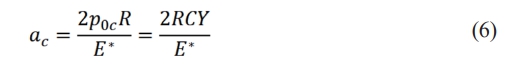
In the case of the sealing structure of the premium thread, the spherical surface with radius R can be considered as part of a cylinder, and the tapered surface can be considered as a plane tangential to the spherical surface, with the length L of the plane being the circumference of the oil casing at the sealing surface, as shown in Fig. 1. For the other common metal/metal seal structure of premium threads, the tapered/tapered structure, can also be considered as a special case when the radius of the sphere is infinite, and the following analysis still applies.
According to Hertz theory, when a cylinder is in contact with a plane, the contact area is a rectangle of length L and width 2a, see Fig. 1. The contact pressure p distribution is semi-elliptical cylindrical in shape [11], and the magnitude can be expressed as:
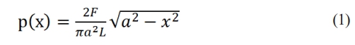
In the formula, x is the radial distance of the contact point from the contact center, a is the contact half-width, and F is the external load.
When x = 0 (at the center of the contact area), the maximum contact pressure is applied, with the value
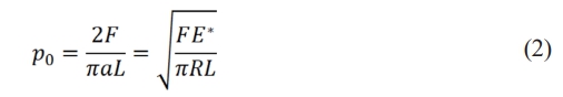
In the formula, E* is the equivalent elastic modulus, E*=E/(1-μ2), and E is the elastic modulus. μ is the Poisson's ratio, and R is the radius of the cylinder.
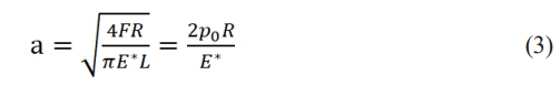
Based on the relationship between the contact pressure and the external load causing the contact pressure, the value of the contact half-width a is obtained as:
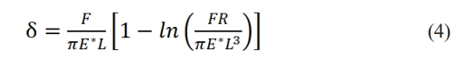
Puttock used a mathematical simplification to derive an approximate solution for the crushing displacement of the cylinder [12]:
The above equations are all derived in the elastic range based on the elastic theory, in the elastic contact process. The contact pressure increases with the increase of the load F, which eventually reaches the yield strength or even exceeds the yield strength of the material. Green further deduced the critical values of the parameters of the cylindrical and planar contact. respectively, as follows [13]:
Critical contact pressure:

Critical contact half-width:
Critical unit contact load:
In the formula, Y is the yield limit of the material and C is the coefficient.The expression is as follows:
|
Fig. 1 Schematic diagram of cylindrical and planar contact. |
The author designed a premium threaded joint CBS4 with a spherical/tapered sealing structure. One specification of this premium threaded joint (Φ139.7×9.17 mm P110 steel grade) has passed the evaluation test of CAL-IV that is the highest level specified in API RP 5C5-2017 [14] standard, and is being further promoted to the oilfield. Other specifications are still under further trial production. In this paper, the design of the sealing structure and the calculation of parameters of this joint are illustrated by taking the CBS4 premium thread of Φ139.7×9.17 mm P110 steel grade as an example.
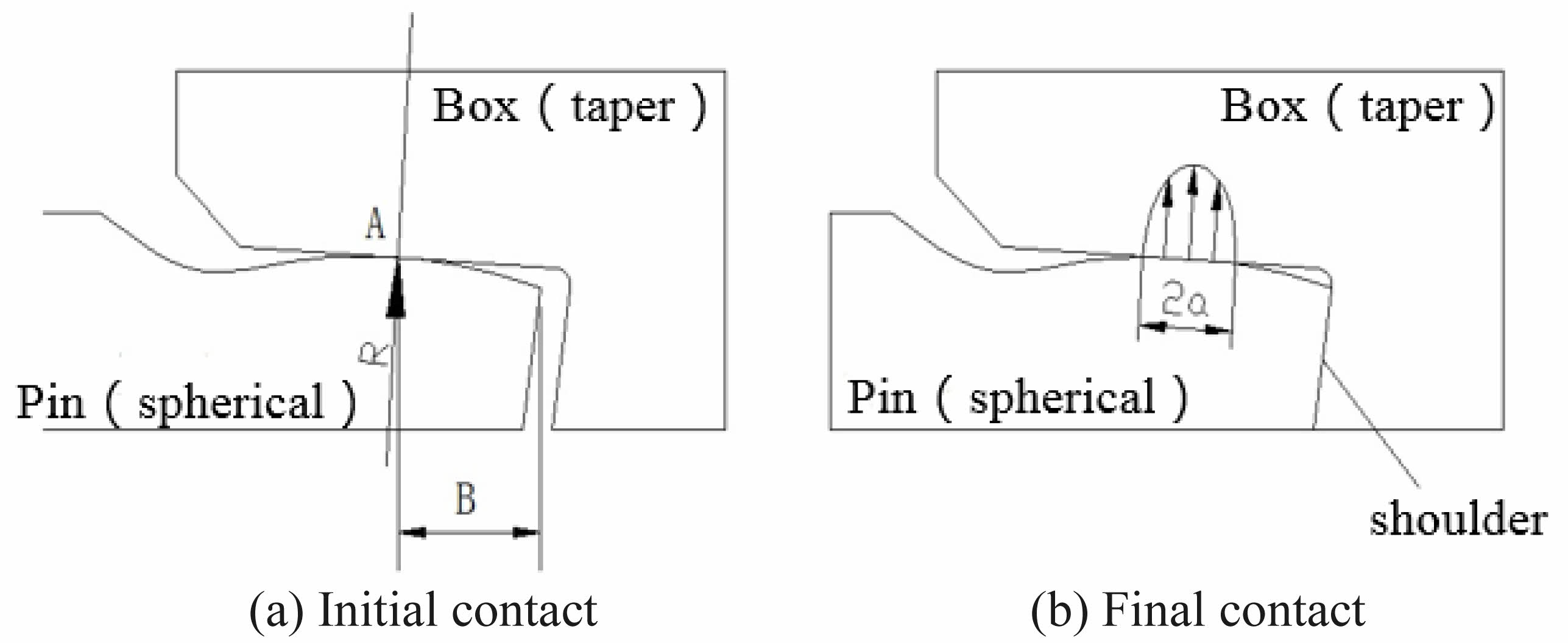
As shown in Fig. 2, the metal/metal sealing structure of the CBS4 premium threaded joint adopts the form of spherical surface of the pipe body and tapered surface of the coupling, and the taper of the coupling sealing taper is set to 1:10. The shoulder surface of the coupling and the end surface of the pipe body are inverted to 15°, thus forming a -15° reverse torque shoulder, which serves as the making up positioning and controls the interference between the thread and the metal sealing structure. At the beginning of the joint, the spherical surface of the pipe body is tangent to the conical surface of the joint at point A. In the initial contact between the spherical surface and the conical surface, the joint is under the action of a certain torque of the making up. After the joint is screwed into place, the spherical surface and the conical surface form a radial interference fit, which generates a certain contact pressure and plays a major role in sealing. At the same time, the torque shoulder contact produces an axial interference fit, which plays an auxiliary sealing role. The tangent point A of the spherical surface of the pipe cannot be too close to the shoulder. If it is too close, on the one hand, the sealing surface will be affected by the axial interference of the shoulder. On the other hand, it is also easy to damage the sealing surface during the downhole process. Through repeated tests and calculations, the distance B from the CBS4 cut point A to the table shoulder was set at 12.5 mm.
For the spherical/tapered seal structure of the above CBS4 premium thread, the key of design is to determine the size of the spherical radius R and the size of the interference between the spherical/tapered surfaces. As shown in Fig. 2, if the tapered surface and the spherical surface are expanded in the circumferential direction, they become a plane and a cylindrical surface, respectively. Also, since the stiffness of the joint is much greater than that of the pipe body, the contact between the two parts can be regarded as a Hertz contact between the cylinder and the plane.
Using the Hertz contact theory, once the radius of the spherical surface is determined, the contact length and contact pressure of the spherical/tapered seal can be calculated. For a CBS4 premium threaded joint of Φ139.7×9.17 mm P110 steel grade, the material yield limit Y=758 MPa, Poisson's ratio μ=0.3, and the value of coefficient C can be obtained according to equation (8): C=1.795. further using equation (5), the critical contact pressure between sealing surfaces p0c=CY=1360.6 MPa. That is to say, in seal design, the contact pressure between the spherical/cone seal should not exceed 1360.6 MPa. Otherwise the sealing surface will be permanently deformed after the making up, affecting the sealing performance of the joint in the repeated upper and making up states.
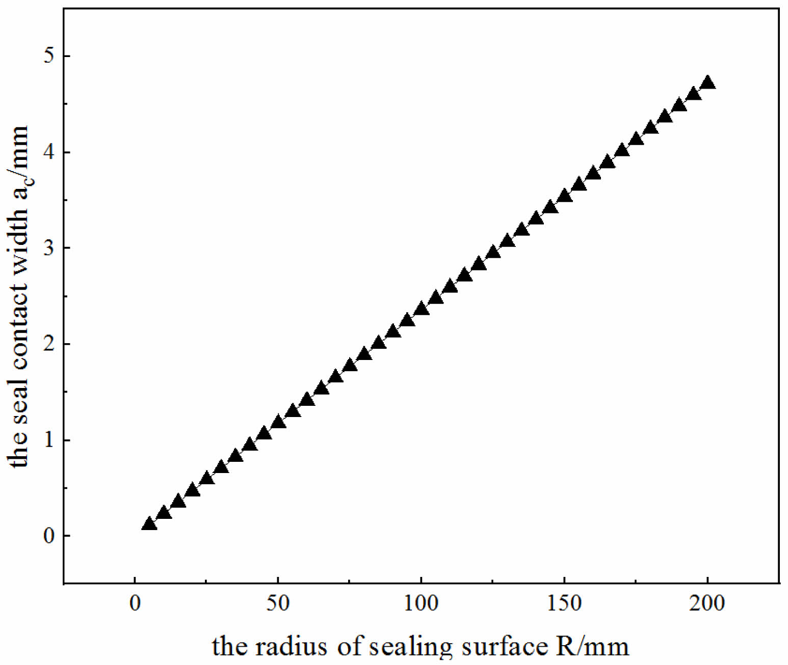
The material of the joint is mild steel and the modulus of elasticity E=2.1×10⁵Pa, then the equivalent modulus of elasticity E*=230769.2Pa is obtained from equation (2). If the radius of the spherical surface R=64 mm, the contact half-width of the spherical/tapered seal can be obtained by substituting the above parameters into equation (6): ac=0.7547 mm in the Fig. 3. In the case of the radius of the spherical surface R=64 mm, the contact width of the sealing surface of the joint should not exceed 2ac=1.509 mm, otherwise it will lead to the yielding of the sealing surface.
For the CBS4 premium thread, the diameter of the sealing surface at the apex of the sealing sphere D=133.5 mm, then the length of the sphere and tapered surface after expansion in the circumferential direction is L=πD=419.4 mm. Further substituting the value into equation (7), the maximum contact force generated between the sphere/tapered surface is Pc=676.4 kN. This contact force is the load value obtained by multiplying the contact pressure by the contact area.
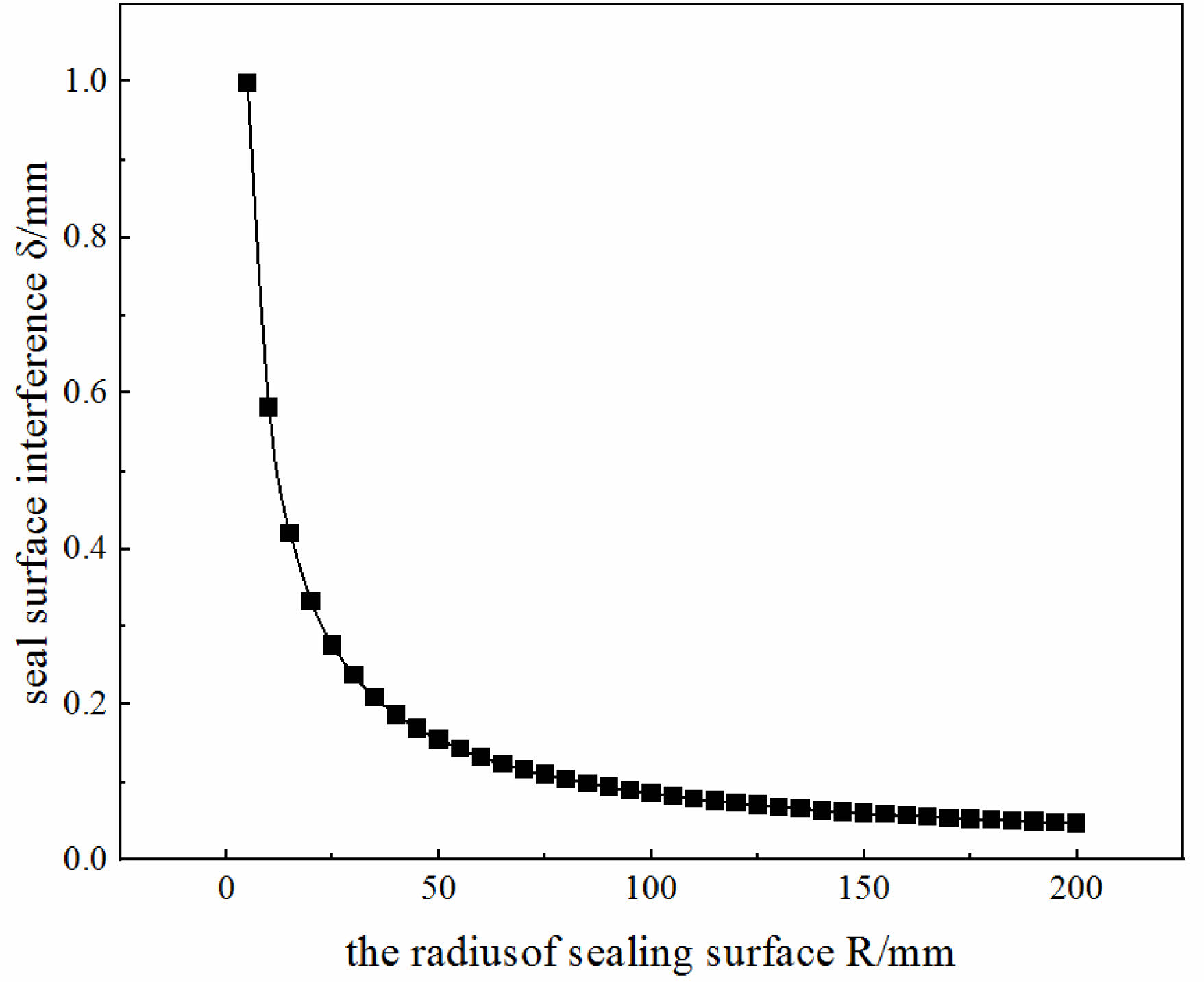
Substituting this contact force into equation (4), the maximum interference between the sealing sphere and the tapered surface is calculated as δ=0.1214 mm in the Fig. 4. It is the local deformation of the sphere with respect to the tapered surface, and for premium threaded joints. The interference also includes the rigid displacement of the joint and the pipe body due to the force, so it is slightly larger than this calculated value.
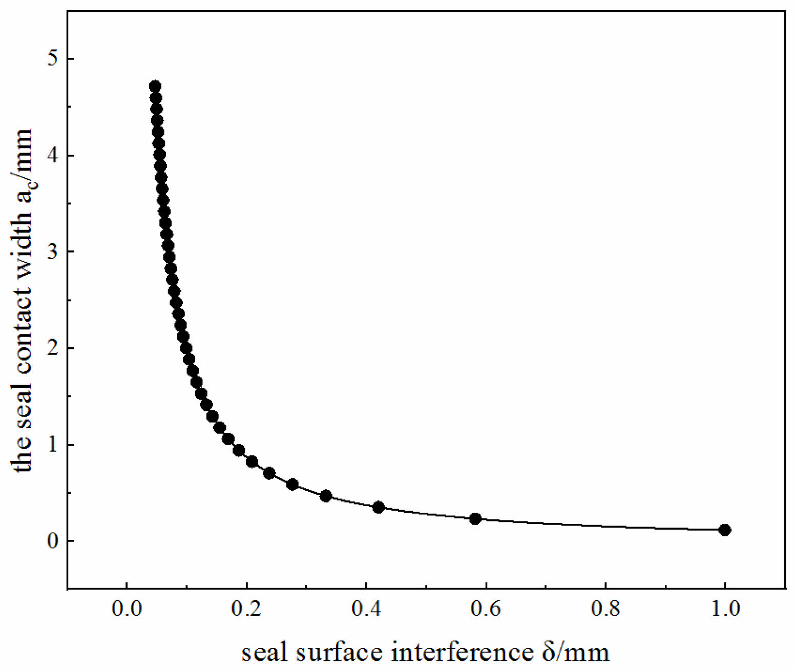
As can be seen, with the known mechanical properties of the material and the radius R of the sealing spherical surface, it is easy to calculate the contact width and seal surface interference of the spherical/tapered seal of the premium threaded joint using Hertz theory in the Fig. 5. Furthermore, it is possible to obtain the value of the load generated by the contact width on the sealing surface and the size of the interference between the spherical/tapered surface.
For the premium thread, the integral of the contact pressure along the contact length on the metal sealing surface is generally defined as the sealing strength, and the greater the sealing strength the better the sealing effect [15]. After obtaining the contact length and critical contact pressure of the spherical/tapered seal structure, the seal strength magnitude can be estimated. After setting different R values for repeated comparisons, the design parameters for the Φ139.7 × 9.17 mm CBS4 premium threaded spherical/tapered structure were determined as follows: spherical radius R = 64 mm and interference δ = 0.1214 mm.
|
Fig. 2 Schematic diagram of a special threaded joint sealing structure. |
|
Fig. 3 Relationship between sealing surface contact radius and contact width. |
|
Fig. 4 Relationship between sealing surface contact radius and sealing interference. |
|
Fig. 5 Relationship between sealing surface interference and contact width. |
The reliability of the above design of the spherical/tapered seal structure of the premium threaded joint based on Hertz theory needs further verification. In this paper, the analytical model of CBS4 premium threaded joint of Φ139.7×9.17 mm P110 steel grade was established by using ABAQUS finite element software, and the calculation results of the two methods were compared and analyzed.
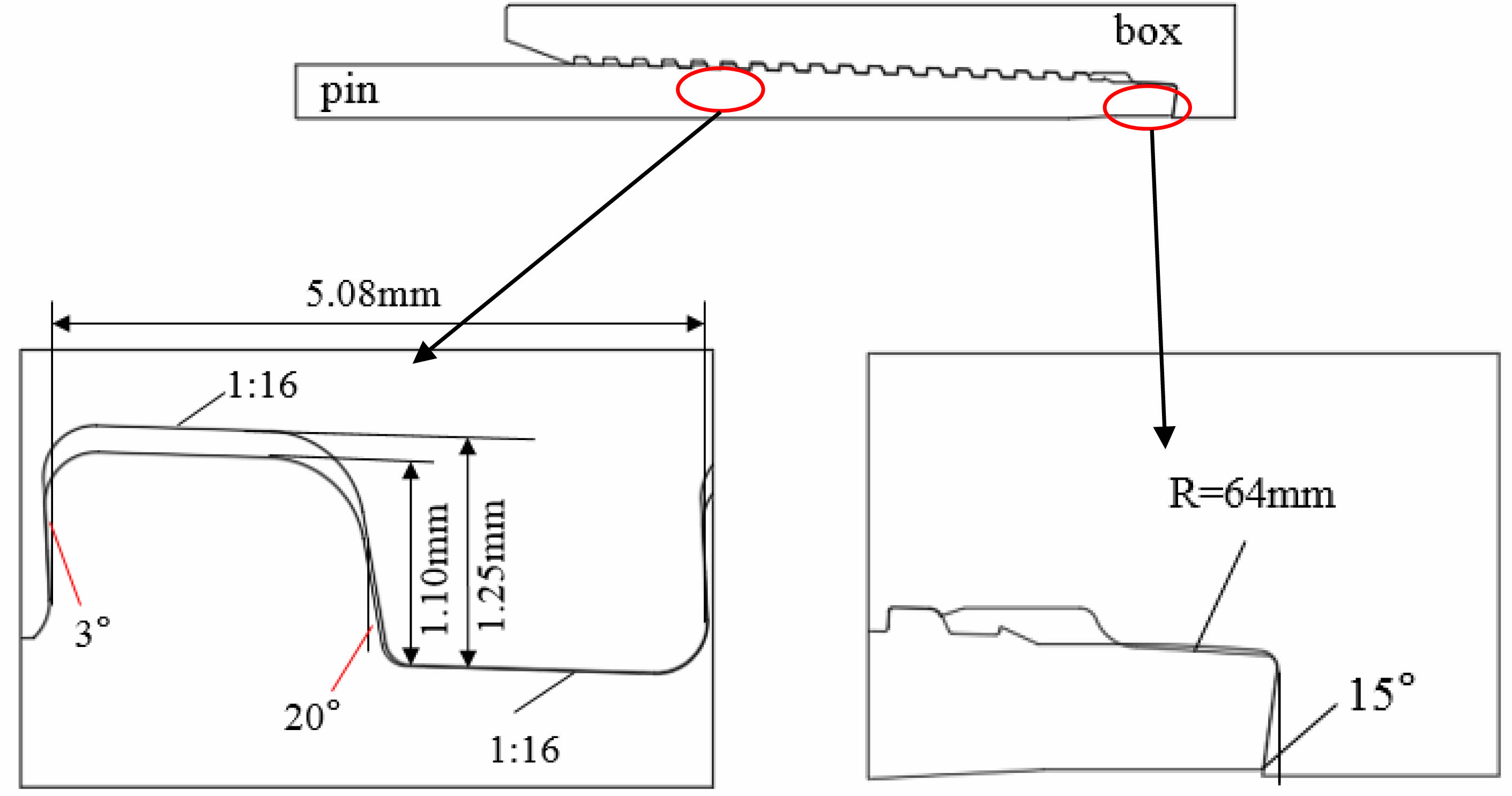
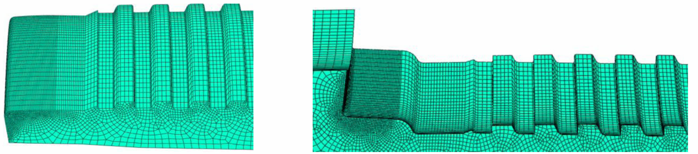
The geometric parameters of the finite element model are as follows: CBS4 joint has a thread guiding surface angle of 20°, a bearing surface angle of 3°, a torque table shoulder surface angle of -15°, a pin thread tooth height of 1.10 mm, a box thread tooth height of 1.25 mm, a pitch of 5.08 mm, a taper of 1:16, and a spherical radius of the sealing structure of R=64 mm in the Fig. 6. According to the symmetry of the joint, axial displacement is applied at each node of the symmetry surface of the joint Constraint. The finite element model and mesh of the premium threaded joint are shown in Fig. 7. A four-node quadrilateral bilinear non-coordinated axisymmetric cell was used for the mesh, and the mesh was locally refined at the threads, sealing surface and shoulders to increase the accuracy of the analysis results.
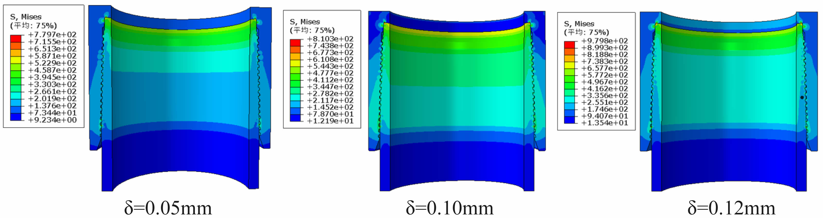
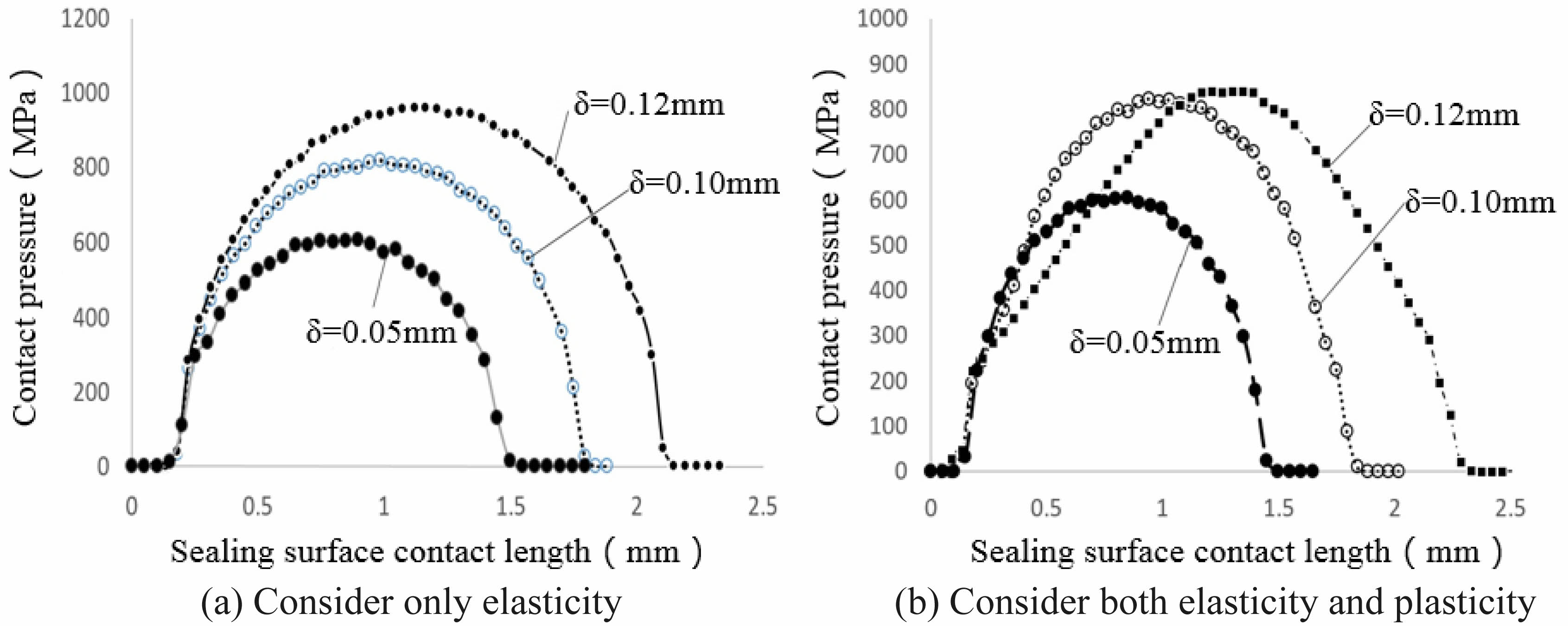
The friction between the threads, sealing surface and shoulder surface was simulated using the Coulomb model, and the friction coefficient was taken as 0.02 [16]. The material of the coupling and the pipe body are the same, with modulus of elasticity 2.1×10⁵ MPa, Poisson's ratio 0.3, yield strength 758 MPa, tensile strength 980 MPa, and elongation 15%. According to the test results, the interference between the inner and outer threads is 0.1±0.06 mm to ensure that the torque shared by the threads accounts for 30-60% of the total torque, so the model takes a nominal interference of 0.05mm and keeps it constant. According to the calculation result of Hertz theory, the maximum interference of the spherical/tapered surface is 0.12 mm, beyond which the seal surface will show local yielding. Therefore, the finite element model sets the interference between the sealing spherical and tapered surfaces to 0.05, 0.10 and 0.12 mm, respectively in the Fig. 8 and Fig. 9. Studying the contact length and contact pressure distribution of the sealing surfaces under such interference, the calculation results are shown in Fig. 10.
Firstly, assuming that the material is linearly elastic and plasticity is not considered, the contact pressure distribution along the sealing surface is semi-elliptical, see Fig. 11a, which is in accordance with the Hertz contact theory as shown in Fig. 1. When the seal surface overfill is 0.05 mm, the contact width of the spherical/tapered surface is about 1.2 mm, which is lower than the critical width (2ac=1.509 mm) calculated in the previous section, indicating that the seal surface has not reached the critical state at this time; when the seal surface overfill is 0.10 mm, the contact width of the spherical/tapered surface is about 1.54 mm, which is slightly larger than the critical contact width, and further observation of the contact point at the equivalent VME stress. The contact point reaches 764 MPa, which is slightly greater than the critical stress of 758 MPa. Continuing to increase the seal surface interference to 0.12 mm resulted in a further increase in contact pressure and contact width with a constant trend in distribution, both of which are consistent with Hertz contact theory.
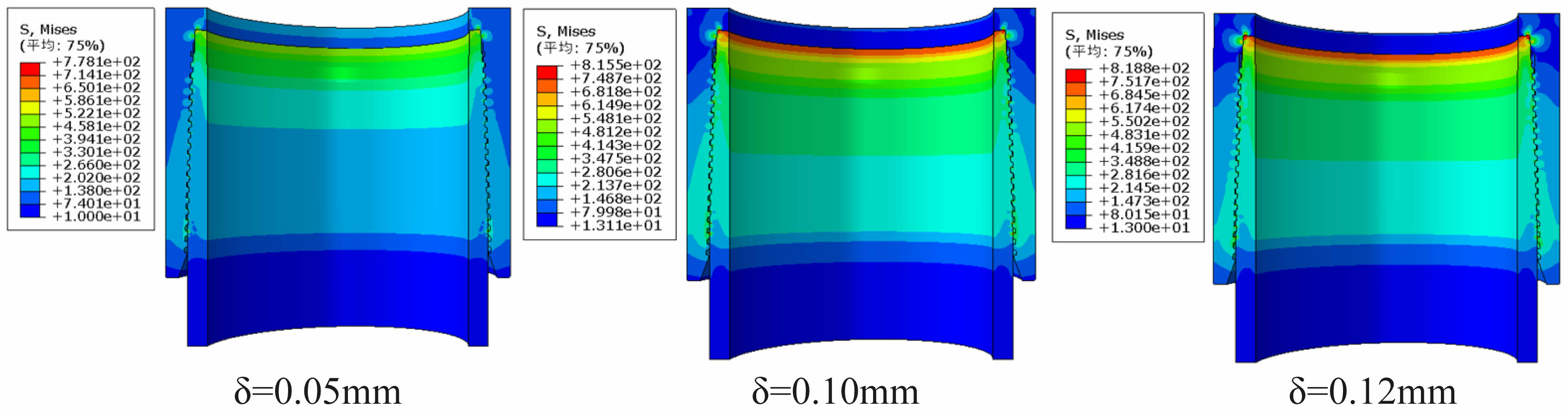
Considering the elasticity and plasticity of the material at the same time, the calculation results are shown in Fig. 10b. When the overfilling amount of the sealing surface is 0.05 mm, the contact pressure distribution curve is the same as Fig. 10a, and the material is in the elastic range. When the seal surface overfill increases to 0.10 mm, the contact pressure distribution curve is also basically the same as Fig. 10a. It excepts that the curve on the left side crosses with the overfill amount equal to 0.05 mm, indicating that local yielding of the seal surface occurs, but the seal surface contact width is basically unchanged, still about 1.54 mm, indicating that the yielding area is small. Compare the maximum contact pressure of Fig. 10b with that of Fig. 10a: In Fig. 10a, the maximum contact pressure of the curve with a seal overfill of 0.10 mm is 819 MPa, and in Fig. 10b, the corresponding maximum contact pressure is 822 MPa, which basically remains the same. Continuing to increase the seal surface overfill to 0.12 mm, the contact pressure also continues to increase if material yielding is not considered (in Fig. 10a). If yielding is considered, the maximum contact pressure is 840 MPa, which is only 18 MPa greater than the 822 MPa at 0.10 mm overfill, indicating that significant yielding of the seal surface has occurred at this time.
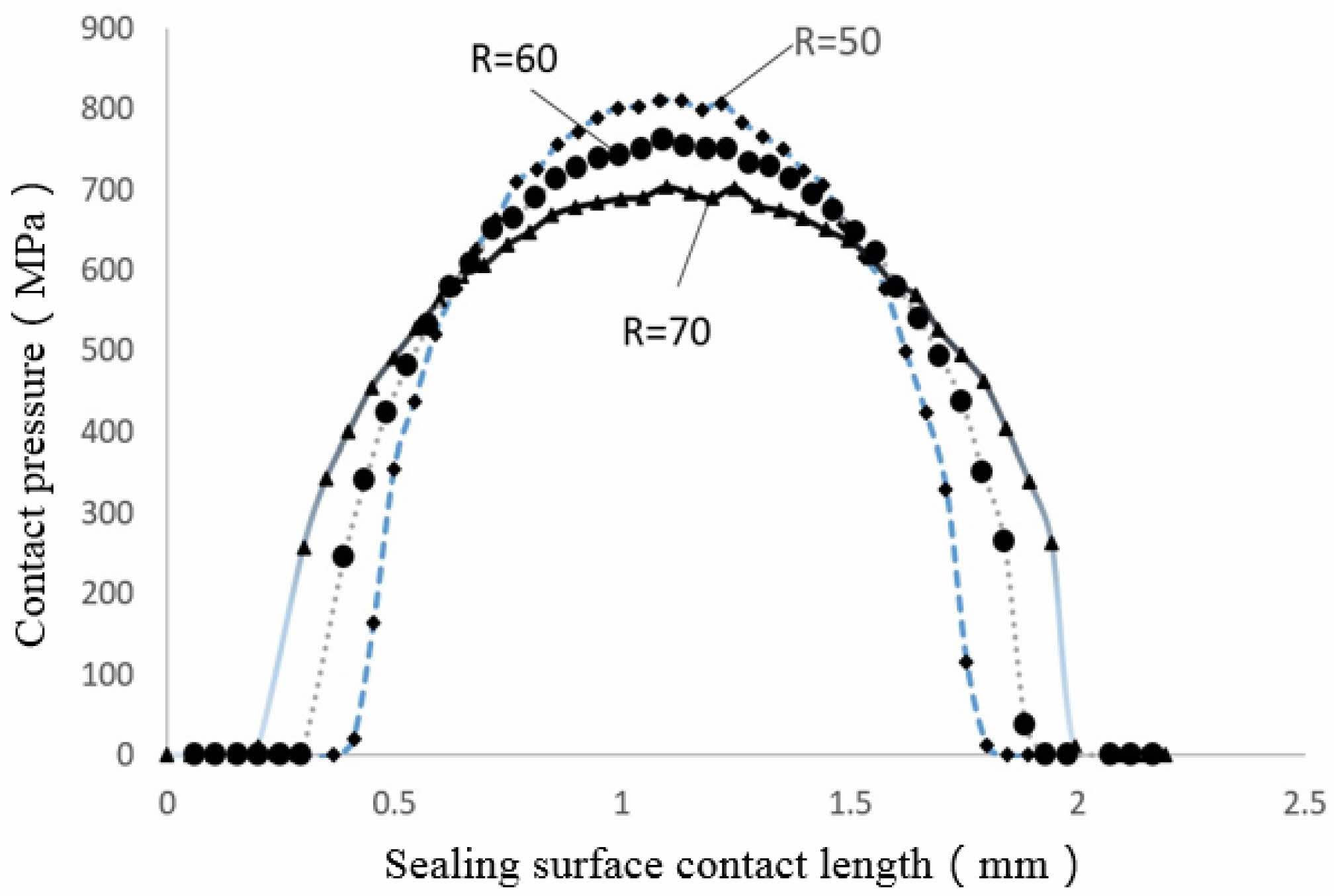
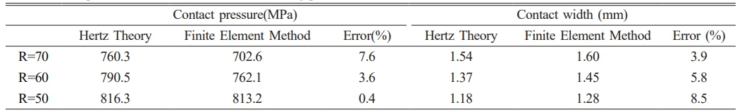
To further verify the reliability of the spherical/tapered seal structure using Hertz theory, the contact pressure and critical contact width of the seal surface were calculated using Hertz theory and the finite element method for spherical radii R=70, 60, and 50 mm, in the Fig. 11. The calculation results are shown in Fig. 12 and Table 1.
It can be seen that for the premium threaded joint with Φ139.7×9.17 mm P110 steel grade. The maximum error of the contact width calculated by using the Hertz theory is 8.5% compared with the finite element calculation result, and the maximum error of the contact pressure calculation formula modified by the Hertz theory is 7.6% compared with the finite element result, which is acceptable in engineering. This error is acceptable in engineering, thus indicating that it is feasible to use Hertz theory to calculate the sealing parameters of the premium threaded joints and to design the spherical/tapered sealing structure of the premium threaded joints.
|
Fig. 6 Structure of the CBS4 premium threaded. |
|
Fig. 7 Finite element model and meshing of a special threaded joint. |
|
Fig. 8 Finite element simulation results considering only elasticity. |
|
Fig. 9 Finite element simulation results considering both elasticity and plasticity. |
|
Fig. 10 Distribution of contact pressure along the sealing surface. |
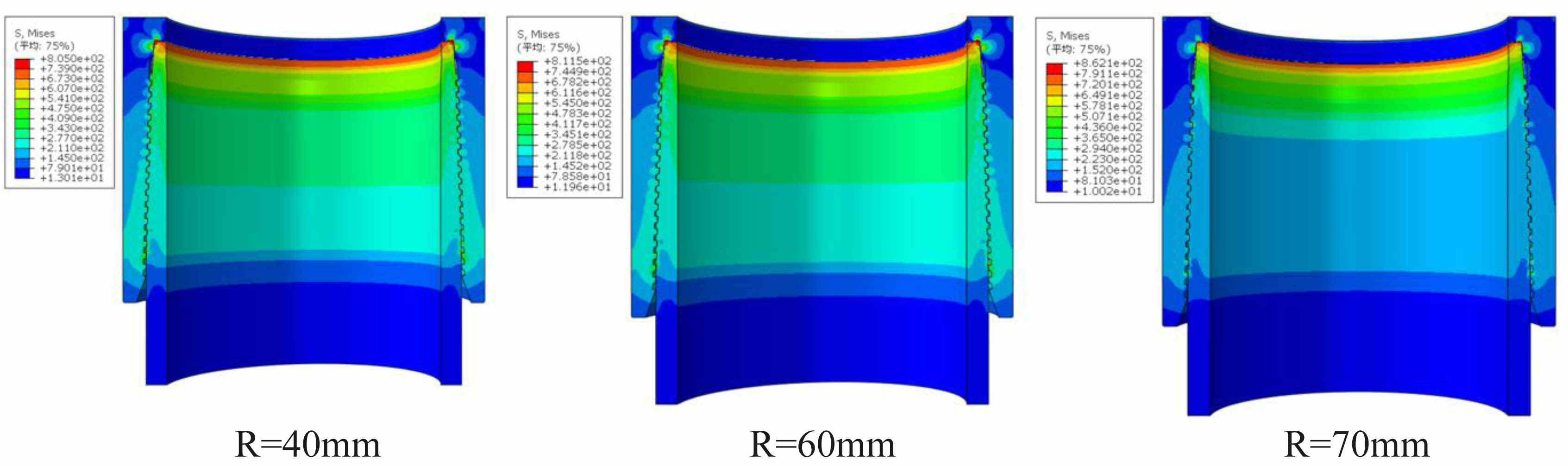
|
Fig. 11 Finite element simulation results for three radii. |
|
Fig. 12 Contact pressure distribution for different spherical radii. |
Two pairs of premium threaded joints of Φ139.7×9.17 mm P110 steel grade (including two each of pin and box threaded joints) were machined by CNC machine. The sealing surface of the box thread is tapered with a taper of 1:16, and the sealing surface of the pin thread is spherical with a spherical radius of R=64 mm, and the spherical surface is tangential to the tapered surface after tightening with an interference of 0.10 mm.
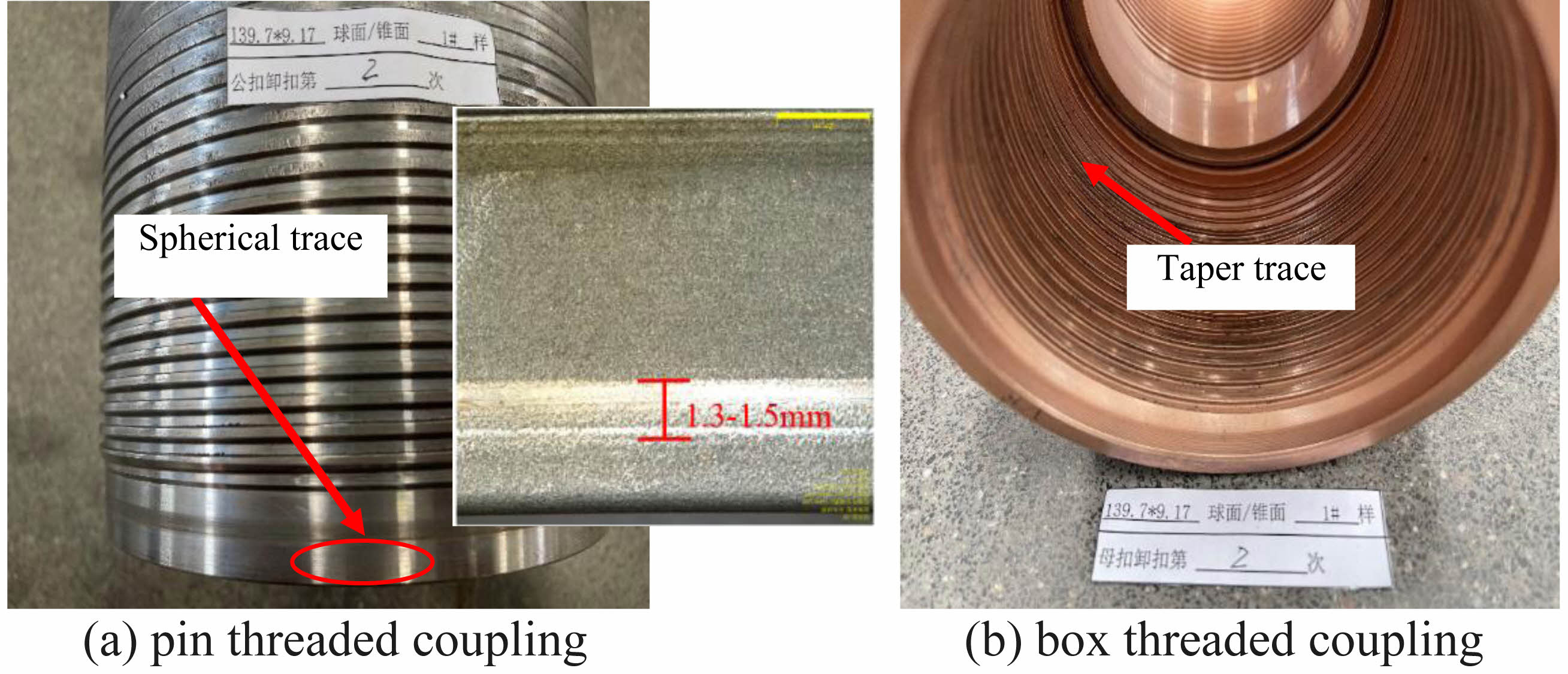
After the joints were machined, a layer of soft metal (copper alloy) was plated on the surface of the box threads, with a thickness of about 8 to 10 μm on the sealing cone surface, and the pin threads were left without surface treatment. The box and pin threads were then joined together using an make up tester, and the upper buckling torque was set to 9950 N·m. The morphology of the box and pin threaded joints after two up-and-down cycles is shown in Fig. 13. Since the morphology of the 2 pairs of joints is close, only the results of sample No. 1 are given here.
Since metal/metal is interference contact, it is very difficult to detect the contact pressure on the contact surface. The contact pressure on the sealing surface cannot be obtained by resistive strain measurement, and the errors of photoelasticity measurement and ultrasonic measurement are large [17]. Therefore, this test failed to measure the magnitude of the contact pressure.But the contact width was measured relatively accurately. As shown in Fig. 13a, the soft metal of the inner thread sealing cone extruded on the outer thread sealing sphere, forming a uniform band trace with a width of about 1.3-1.5 mm, which is very close to the calculated value (1.37 mm) with an error of about 8%. Therefore, it can be proved that the method of calculating the contact pressure and contact length of the sealing surface of the premium threaded joint using Hertz theory in this paper is feasible, and the design of the spherical/tapered sealing structure of the premium threaded joint using this method is also feasible.
In addition, the CBS4 premium thread of Φ139.7×9.17 mm P110 steel grade has also passed the evaluation test of CAL-IV, which is highest level specified in API RP 5C5-2017 standard. Without leakage, it proves that the design of the spherical/tapered sealing structure by this method is reliable.
|
Fig. 13 Contact width test results. |
(1) For the spherical/tapered seal structure of the special threaded joint, the expressions for calculating the sealing surface contact pressure and contact width were obtained based on the Hertz theory, and a new spherical/tapered seal structure with good gas sealing performance was designed based on the calculation results. The Herz theoretical model of sphere/taper contact can be extended with corresponding dimensions and applied to oil casing and tubing with different radii and wall thicknesses.
(2) For the CBS4 premium threaded joint of Φ139.7×9.17 mm P110 steel grade designed in this paper, the contact pressure and contact length of the sealing surface calculated by Hertz theory have very small errors compared with the FEM analysis results. A variety of radius sizes of the sphere/taper sealing surface model, which compare with the same size of the taper to taper model, and result in a more detail study of the two models.
(3) The design method of spherical/tapered seal structure of premium threaded joints obtained in this paper is clear in concept and fast in calculation, which provides a new analysis and calculation means for the design of seal structure of special threaded joints.
China Petroleum Science and Technology Innovation Fund Project “Research on New Type of Metal Seal of Expanding Sleeve Pipe Joint for Horizontal Well Sleeve Variation Management” (2019D-5007-0305), National Natural Science Foundation of China (NSFC) Joint Fund for Petrochemical Industry (JFPC) Key Project “Fundamental Theory Research on Nonlinear Dynamics and Dynamic Safety of Ultra-deep Well Drilling Column” (No. U1663205).
The datasets generated during and/or analyzed during the current study are available from the corresponding author on reasonable request.
The author declares that there is no conflict of interest.
- 1. G.R. Murtagian, V. Fanelli, J.A. Villasante, D.H. Johnson, and H.A. Ernst, J. Tribol. 126[6] (2004) 591-596.
-

- 2. J. Jiandong, L. Yuanhua, L. Yufei, X. Nanxing, and D. Kuanhai, J. Southwest Pet. Univ. Nat. Sci. Ed. 44[4] (2022) 165-173.
- 3. W. Song, A. Ji, R. Li, Y. Zhang, and J. Wang, Mechatronic Eng. 32[7] (2015) 954-957.
- 4. Y.Cao, Y. Dou, Y. Yu, Y. Zhang, and X. Li, Lubr. Seal. 44[9] (2019) 7-12.
- 5. J.R. Xie and C. Matthews, in proceedings of SPE Canada Heavy Oil Technical Conference, February 2017.
- 6. L.X. Gao, Y. Jin, and J.Q. Zhang, J. Mech. Eng. 41[3] (2005) 216-220.
-
- 7. Y. Zhang, Z. Lian, Q. Zhou, and X. Li, Press. Vessel Technol. 36[12] (2019) 23-29.
- 8. Q. Song, Y. Liao, G. Wang, and X. Zhang, Min. Res. Dev. 39[10] (2019) 103-107.
- 9. H. Xu, B. Yang, Z. Zhang, and X. Li, Chin. J. Appl. Mech. 38[3] (2021) 1258-1263.
- 10. Y. Zhang, Z. Lian, Q. Zhou, and X. Li, J. China Univ. Pet. (Nat. Sci. Ed.) 44[3] (2020) 135-140.
- 11. B. Xu, X. Luo, and X. Liu, in “Contact Mechanics” (Higher Education Press, Beijing, 1992).
- 12. M.J. Puttock and E.G. Thwaite, in “Elastic Compression of Spheres and Cylinders at Point and Line Contact” (CSIRO, Melbourne, 1969).
- 13. R.G. Vijaywargiya, Int. J. Nonlinear Mech. 42[3] (2007) 914-927.
-
- 14. American Petroleum Institute, Procedures for Testing Casing and Tubing Connections, (API, Washington, DC 2017).
- 15. Q. Di, F.Chen, W. Wang, and Xue Li, Pet. Sci. 33[5] (2012) 871-877.
- 16. J.Y. Xie, L.W. Huang, and Q. An, J. East China Univ. Sci. Technol. (Nat. Sci. Ed.) 42[5] (2016) 722-729.
- 17. Y. Wang, Ultrasonic Measurement of Contact Stress and Contact State Evaluation of Small Interference Parts [D] (Dalian Univ. Technol., Dalian, 2019).
 This Article
-
2025; 26(5): 815-823
Published on Oct 31, 2025
- 10.36410/jcpr.2025.26.5.815
- Received on Oct 22, 2024
- Revised on Feb 17, 2025
- Accepted on Mar 1, 2025
Services
- Abstract
introduction
theoretical model of spherical/conical seal structure
design of sealing structure and calculation of parameters for special threaded joints
hertz theory and finite element method comparison analysis
physical test verification
conclusion
foundation project
- Availability of data and materials
- Conflict of Interest
- References
- Full Text PDF
Shared
Correspondence to
- Lianxin Gao
-
School of Machinery and Power Engineering, East China University of Science and Technology, Shanghai 200237, China
Tel : 021-64252748 - E-mail: Lianxin_Gao@outlook.com
Clean-Energy Research Institute(CRI), Hanyang University, 222, Wangsimni-ro, Seongdong-gu, Seoul, 04763, Korea
E-mail: jcpr@hanyang.ac.kr