


- Hierarchically integrated NiFe LDH/Ni3S2 on Ni foam as a highly efficient electrocatalyst for alkaline oxygen evolution
Yun Seok Jang, Tae Kwang An, Dong Hyun You and Jeong Ho Ryu*
Department of Materials Science and Engineering, Korea National University of Transportation, Chungju, 50 Daehak-ro, Chungju, Chungbuk 27469, South Korea
This article is an open access article distributed under the terms of the Creative Commons Attribution Non-Commercial License (http://creativecommons.org/licenses/by-nc/4.0) which permits unrestricted non-commercial use, distribution, and reproduction in any medium, provided the original work is properly cited.
In this work, a hierarchical NiFe-LDH/Ni3S2@Ni-foam heterostructure was rationally constructed on conductive Ni foam via a two-step hydrothermal strategy and evaluated as an efficient oxygen evolution reaction (OER) electrocatalyst. Thiourea-assisted sulfurization of Ni foam produced vertically aligned Ni3S2 nanosheets, which served as a highly conductive and porous scaffold. Subsequent hydrothermal growth of NiFe layered double hydroxide (LDH) nanosheets on the Ni3S2 surface resulted in an intimately coupled NiFe-LDH/Ni3S2@Ni-foam nanoarchitecture. X-ray diffraction and FE-SEM analyses confirmed the successful formation of both Ni3S2 and NiFe-LDH phases and revealed a well-defined hierarchical nanosheet network. XPS further demonstrated the coexistence of Ni²⁺ and Fe³⁺ species and suggested strong interfacial electronic coupling between NiFe-LDH and Ni3S2. Benefiting from the synergistic combination of the conductive Ni₃S₂ backbone and the highly active NiFe-LDH nanosheets, the NiFe-LDH/Ni₃S₂@Ni-foam electrode exhibited superior OER performance, delivering overpotentials of 315 and 325 mV at 50 and 100 mA·cm-2, respectively, along with a low Tafel slope of 72 mV·dec⁻¹, thereby outperforming both Ni₃S₂@Ni-foam and NiFe-LDH@Ni-foam. Electrochemical impedance spectroscopy and ECSA analysis further revealed reduced charge-transfer resistance and significantly increased active surface area for the heterostructured sample. This study provides a simple and effective strategy for designing high-performance OER electrocatalysts via interfacial engineering of sulfide and LDH nanostructures.
Keywords: Electrocatalysis, Oxygen evolution reaction, NiFe-LDH/Ni3S2@Ni-foam, Interfacial engineering, Hydrothermal synthesis
The increasing demand for sustainable and clean energy has spurred an intensive search for efficient electrocatalysts for the oxygen evolution reaction (OER), a key half-reaction in water-splitting technologies [1]. However, the sluggish four-electron transfer kinetics of OER severely hamper its overall efficiency [2]. Noble-metal–based catalysts, such as IrO₂ and RuO₂, offer excellent activity but suffer from scarcity and high cost, making them unsuitable for large-scale application [3-5]. Therefore, the development of low-cost, earth-abundant transition-metal–based catalysts with high catalytic activity and durability is highly desirable [6].
Among various candidates, nickel-based compounds have been extensively investigated owing to their suitable electronic structure, tunable redox properties, and outstanding alkaline stability [7, 8] In particular, nickel sulfides (e.g., Ni3S2) grown on conductive metallic foams have attracted considerable attention. Ni3S2 not only exhibits intrinsic catalytic activity toward OER but also provides high electrical conductivity and abundant exposed active sites [9, 10]. Moreover, metallic Ni foam serves as a highly conductive current collector and offers a three-dimensional porous framework for fast mass transport. Nevertheless, the catalytic activity of individual Ni3S2 is still limited by the intrinsically moderate binding energy of OER intermediates [11].
To overcome this limitation, one promising strategy is the construction of hierarchical heterostructures that combine conductive sulfide backbones and highly active layered double hydroxides (LDHs). Among transition-metal LDHs, NiFe LDH has proven to be an outstanding OER catalyst thanks to the synergistic interaction between Ni and Fe cations, which optimizes the adsorption/desorption energetics of reaction intermediates (M–OOH) [12-14]. In addition, the in-situ formation of heterointerfaces between Ni3S2 and NiFe LDH can facilitate interfacial electron transfer and promote surface reconstruction under OER operating conditions, thereby exposing more catalytically active oxyhydroxide species [15, 16].
Herein, we report the rational design and fabrication of a NiFe-LDH/Ni3S2 heterostructure on Ni foam (NiFe-LDH/Ni3S2@Ni-foam) through a two-step synthetic strategy. First, Ni3S2 was directly grown on Ni foam using a thiourea-assisted hydrothermal sulfurization process. Subsequently, NiFe LDH nanosheets were uniformly integrated onto the Ni3S2@Ni-foam via a hydrothermal method. In comparison, NiFe LDH grown directly on Ni foam (NiFe-LDH@Ni-foam) and Ni3S2@Ni-foam samples were also synthesized for reference. Electrochemical measurements reveal that the hierarchical NiFe-LDH/Ni3S2@Ni foam exhibits a significantly reduced overpotential and Tafel slope compared to both Ni3S2@Ni-foam and NiFe-LDH@Ni- foam samples, demonstrating a clear synergistic enhancement arising from the heterostructure and interfacial coupling. This work provides valuable insight into the rational design of sulfide-LDH heterostructures for high-performance OER catalysts.
Synthesis of NiFe-LDH/Ni3S2@Ni-foam hierarchical heterostructure
Ni foam (1 × 2 cm) was first immersed in 1 M HCl solution for 30 min to remove the oxide layer, and then sequentially rinsed with deionized (DI) water for 10 min and ethanol for 10 min. The cleaned substrate was dried under vacuum at 60 °C for 3 h. Subsequently, thiourea was dissolved in DI water under magnetic stirring to form a clear solution, into which the pretreated Ni foam was immersed. The mixture was transferred into a Teflon-lined autoclave and subjected to hydrothermal treatment at 160 °C for 4 h. After naturally cooling to room temperature, the obtained sample was washed with DI water and ethanol and then vacuum-dried at 60 °C for 12 h, yielding Ni₃S₂@Ni-foam.
Ni(NO3)2·6H2O and Fe(NO3)3·6H2O (molar ratio of Ni:Fe = 1:1) were dispersed in DI water under continuous stirring to form a homogeneous precursor solution. A piece of pre-cleaned Ni foam (prepared as described above) was then immersed in the solution, sealed in a Teflon-lined autoclave, and maintained at 200 °C for 10 h under static conditions. After cooling to room temperature, the sample was thoroughly washed with DI water and ethanol and vacuum-dried at 60 °C for 12 h to obtain NiFe-LDH@Ni-foam.
For the fabrication of the hierarchical heterostructure, the above-prepared Ni₃S₂@Ni-foam was immersed in a precursor solution composed of Ni(NO3)2·6H2O and Fe(NO3)3·6H2O dispersed in DI water (Ni:Fe molar ratio = 1:1). The resulting mixture was transferred to a Teflon-lined autoclave and hydrothermally treated at 200 °C for 10 h. After cooling to room temperature, the product was washed several times with DI water and ethanol to remove residual ions and finally dried under vacuum at 60 °C for 12 h. The final product is denoted as NiFe-LDH/Ni₃S₂@Ni foam.
Characterizations
The crystal structure of the as-prepared samples was examined using an X-ray diffractometer (e.g., Rigaku SmartLab) equipped with Cu Kα radiation (λ = 1.5406 Å), operating at 40 kV and 30 mA. The diffraction patterns were recorded in the 2θ range of 10–80° with a scan rate of 3°/min. The surface morphology and microstructure of the samples were investigated using a field-emission scanning electron microscope (e.g., JEOL JSM-7610F) operated at an accelerating voltage of 5–15 kV. Prior to observation, the samples were fixed on conductive carbon tape and sputter-coated with a thin layer of Au to prevent charging during FE-SEM measurements. The chemical composition and surface electronic states were analyzed by X-ray photoelectron spectroscopy (Thermo Scientific ESCALAB 250Xi) using a monochromatic Al Kα X-ray source (hν = 1486.6 eV). All binding energies were calibrated with respect to the C 1s peak at 284.8 eV. The obtained spectra were deconvoluted using Gaussian–Lorentzian functions.
All electrochemical measurements were carried out
in a standard three-electrode configuration using a Bio-Logic VSP potentiostat. The as-prepared samples (Ni3S2@Ni-foam, NiFe-LDH@Ni-foam, and NiFe-LDH/Ni3S2@Ni foam) were directly used as the working electrode without adding any binder. The OER activity of the samples was evaluated by linear sweep voltammetry (LSV) in 1.0 M KOH electrolyte. LSV curves were recorded in a potential window of 1.0–1.8 V (vs. RHE) at a scan rate of 5 mV/s using the as-prepared samples as the working electrode, a Pt wire as the counter electrode, and an Ag/AgCl (3.5 M KCl) electrode as the reference electrode. Prior to the measurement, the electrolyte was purged with high-purity N2 for at least 30 min to remove dissolved oxygen. The overpotential (η) was calculated by subtracting the thermodynamic potential of OER (1.23 V) from the measured potential at the desired current density. Cyclic voltammetry (CV) tests were performed in the potential window of 0.20–0.60 V vs. Ag/AgCl with a scan rate of 5 mV/s to evaluate the OER activity. The obtained potentials were converted to the reversible hydrogen electrode (RHE) scale [17]. The overpotential was determined at the current density of 50 and 100 mA·cm-2. Electrochemical impedance spectroscopy (EIS) measurements were carried out at an overpotential of 300 mV in the frequency range of 100 kHz to 0.1 Hz, with an amplitude of 5 mV. The Nyquist plots were fitted using an equivalent circuit model to evaluate the charge-transfer resistance (Rct). The capacitive behavior was examined by CV in a non-Faradaic region (typically 0.10–0.15 V vs. Ag/AgCl) at scan rates of 20, 40, 60, 80, and 100 mV/s. The Cdl value was obtained from the slope of the plot of Δj (anodic current density − cathodic current density) versus the scan rate. The electrochemically active surface area (ECSA) was estimated using the equation: ECSA = Cdl/Cs, where Cs (specific capacitance) was assumed to be 40 μF·cm-2 in alkaline media [18].
Phase, morphology and surface characterization
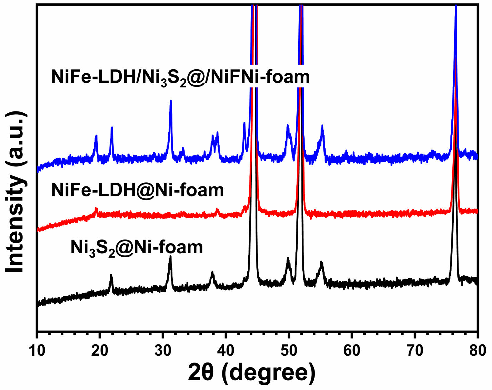
Fig. 1 shows the XRD patterns of (a) Ni3S2@Ni-foam, (b) NiFe-LDH@Ni-foam, and (c) NiFe-LDH/Ni3S2@Ni-foam obtained under the described synthetic conditions. In the case of Ni3S2@Ni-foam (Fig. 1a), several characteristic diffraction peaks are observed at 2θ = 21.7°, 31.1°, 37.8°, 49.7°, and 55.2°, which can be indexed to the (101), (110), (003), (113), and (122) planes of rhombohedral Ni₃S₂ (JCPDS No. 44-1418), demonstrating the successful sulfuration of the Ni foam. In addition, a strong reflection at approximately 44.5° originates from the (111) plane of the underlying metallic Ni foam. For the NiFe-LDH@Ni-foam sample (Fig. 1b), several broad reflections are visible at 2θ ≈ 23° and 34–35°, corresponding to the (006) and (012)/(110) planes of hydrotalcite-like NiFe layered double hydroxide (JCPDS No. 40-0215). It should be noted that the characteristic (003) peak of NiFe-LDH, which normally appears at approximately 11°, is not clearly detected in the XRD pattern. This absence can be ascribed to the low crystallinity and ultrathin nature of the LDH nanosheets grown on the surface of Ni foam, resulting in a broad and low-intensity (003) reflection that is easily masked by the background signal of the substrate. In the case of NiFe-LDH/Ni3S2@Ni-foam (Fig. 1c), the diffraction features of both Ni3S2 and NiFe-LDH are simultaneously observed. The LDH-related reflections at 23° and 34° co-exist with the characteristic peaks of Ni3S2, indicating the successful formation of a heterostructure. Similar to the LDH-only sample, the (003) peak expected near 11° is not clearly visible, which is most likely due to the extremely thin NiFe-LDH layers formed on the Ni3S2 nanosheet surface. Such highly dispersed and poorly crystalline LDH nanosheets usually produce only very broad diffraction features in the low-angle region, and their intensity becomes too weak to be resolved when supported on a conductive substrate. Nevertheless, the coexistence of Ni, Fe and O signals confirmed by EDS/XPS (see below) strongly indicates the successful deposition of NiFe-LDH on the Ni3S2 surface. These results clearly demonstrate that the desired phases were successfully obtained in each synthesis step and that the hierarchical NiFe-LDH/ Ni3S2@Ni-foam heterostructure was constructed without the generation of any impurity phases.
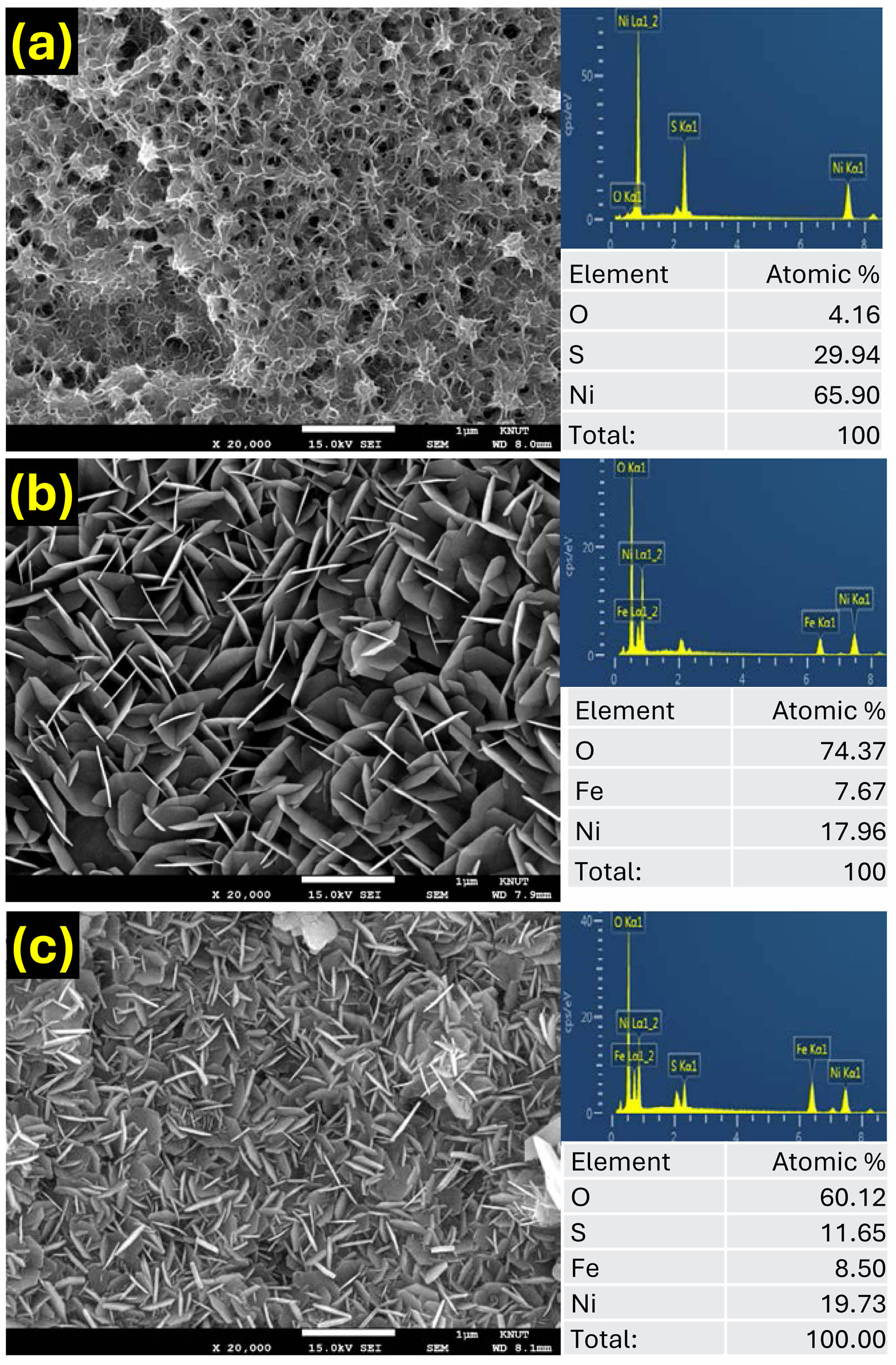
The surface morphology and elemental distribution of the obtained samples were evaluated by FE-SEM and energy-dispersive X-ray spectroscopy (EDS), as shown in Fig. 2. The Ni3S2@Ni-foam sample (Fig. 2a) exhibits a dense layer of vertically oriented nanosheets uniformly covering the entire surface of the Ni foam skeleton. These nanosheets are interconnected and form a three-dimensional porous framework, which can provide abundant electroactive sites and promote electrolyte diffusion during the electrochemical reaction. The corresponding EDS elemental analysis (Fig. 2a) confirms the quantitative existence of Ni and S elements, further indicating the successful sulfurization of the Ni substrate into Ni3S2. In the case of the NiFe-LDH@Ni-foam sample (Fig. 2b), the FE-SEM image shows a typical flower-like morphology composed of numerous ultrathin nanosheets grown directly on the surface of the Ni foam. Compared to the Ni3S2@Ni-foam, the NiFe-LDH nanosheets are relatively thinner and loosely stacked, forming an open and highly accessible architecture. The EDS elemental analysis shows the quantitative existence of Ni, Fe, and O elements, verifying the formation of the bimetallic hydroxide phase.
The hierarchical NiFe-LDH/Ni3S2@Ni-foam sample (Fig. 2c) displays a hybrid morphology in which ultrathin NiFe-LDH nanosheets are uniformly decorated on the surface of the pre-formed Ni3S2 nanosheets. Compared with the two individual samples, the hybrid sample displays a more densely interconnected network in which ultrathin NiFe-LDH nanosheets are uniformly anchored on the surface of Ni3S2 nanosheets. Such intimate interfacial contact is expected to accelerate electron transport and to facilitate the generation of catalytically active oxyhydroxide species during OER operation. This well-defined heterointerface is expected to facilitate fast interfacial electron transport and promote the generation of catalytically active oxyhydroxide species during the OER process.
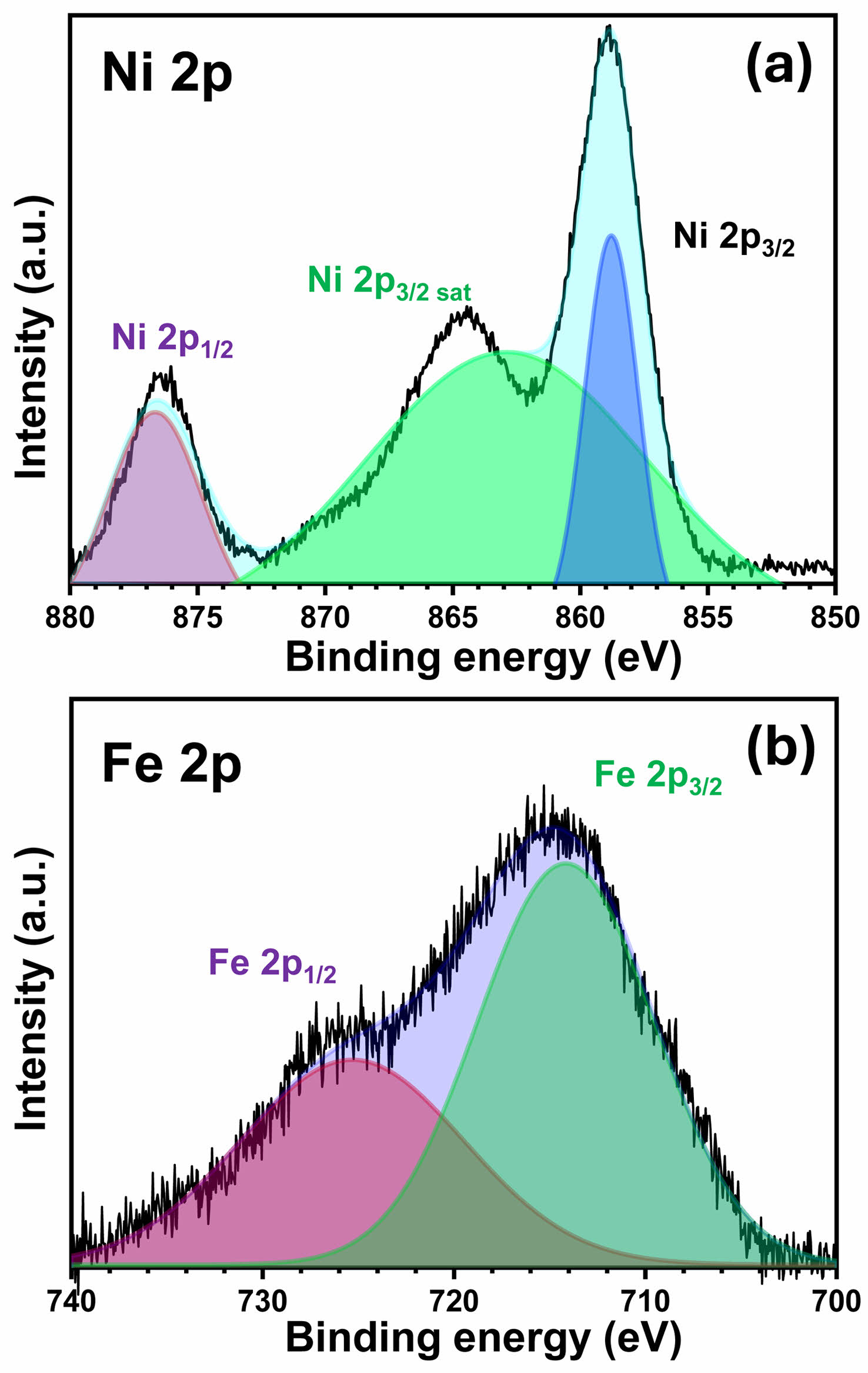
Fig. 3displays the high-resolution XPS spectra of the Ni 2p and Fe 2p regions for the NiFe-LDH/Ni3S2@Ni-foam sample. As shown in Fig. 3a, the Ni 2p spectrum exhibits two prominent peaks located at ~859.1 eV (Ni 2p3/2) and ~876.5 eV (Ni 2p1/2), together with their associated satellite peaks. These binding energy values are characteristic of Ni2+ species in metal hydroxide environments and can be clearly distinguished from metallic Ni or NiS, which typically show lower binding energies. This provides direct evidence that the outer surface consists of a Ni-based hydroxide phase, i.e. NiFe-LDH. In addition, a slight positive shift of the Ni 2p binding energy compared to pure Ni(OH)2 indicates the presence of Fe3+ adjacent to Ni2+ within the LDH layers, suggesting an electronic interaction between the two metal cations [19]. Such interaction is known to promote charge delocalization and to modulate the adsorption energy of OER intermediates.
The Fe 2p spectrum shown in Fig. 3b presents two peaks at ~714.5 eV (Fe 2p3/2) and ~725.6 eV (Fe 2p 1/2), which can be assigned to Fe3+ species in the hydroxide lattice. The absence of any additional peak associated with Fe2+ further confirms that the Fe atoms are incorporated into the LDH structure as trivalent cations. It is worth noting that the Fe 2p peaks exhibit a slight shift toward lower binding energies compared to pure FeOOH, which can be attributed to the strong electronic coupling between Fe3+ and Ni2+ in the LDH lattice. Such a shift indicates that partial electron transfer from Ni to Fe occurs at the heterointerface, leading to an optimized electronic structure for accelerated OER kinetics [20]. Taken together, the Ni 2p and Fe 2p XPS results confirm that a Ni2+–Fe3+ co-hydroxide (NiFe-LDH) has been successfully grown on the surface of the Ni3S2 scaffold. Moreover, the subtle shifts in the binding energies suggest a strong interfacial electronic coupling between NiFe-LDH and the underlying Ni3S2, which is expected to facilitate charge transfer and promote the conversion of Ni/Fe sites into highly active oxyhydroxide species under anodic OER conditions.
Electrochemical performance evaluation
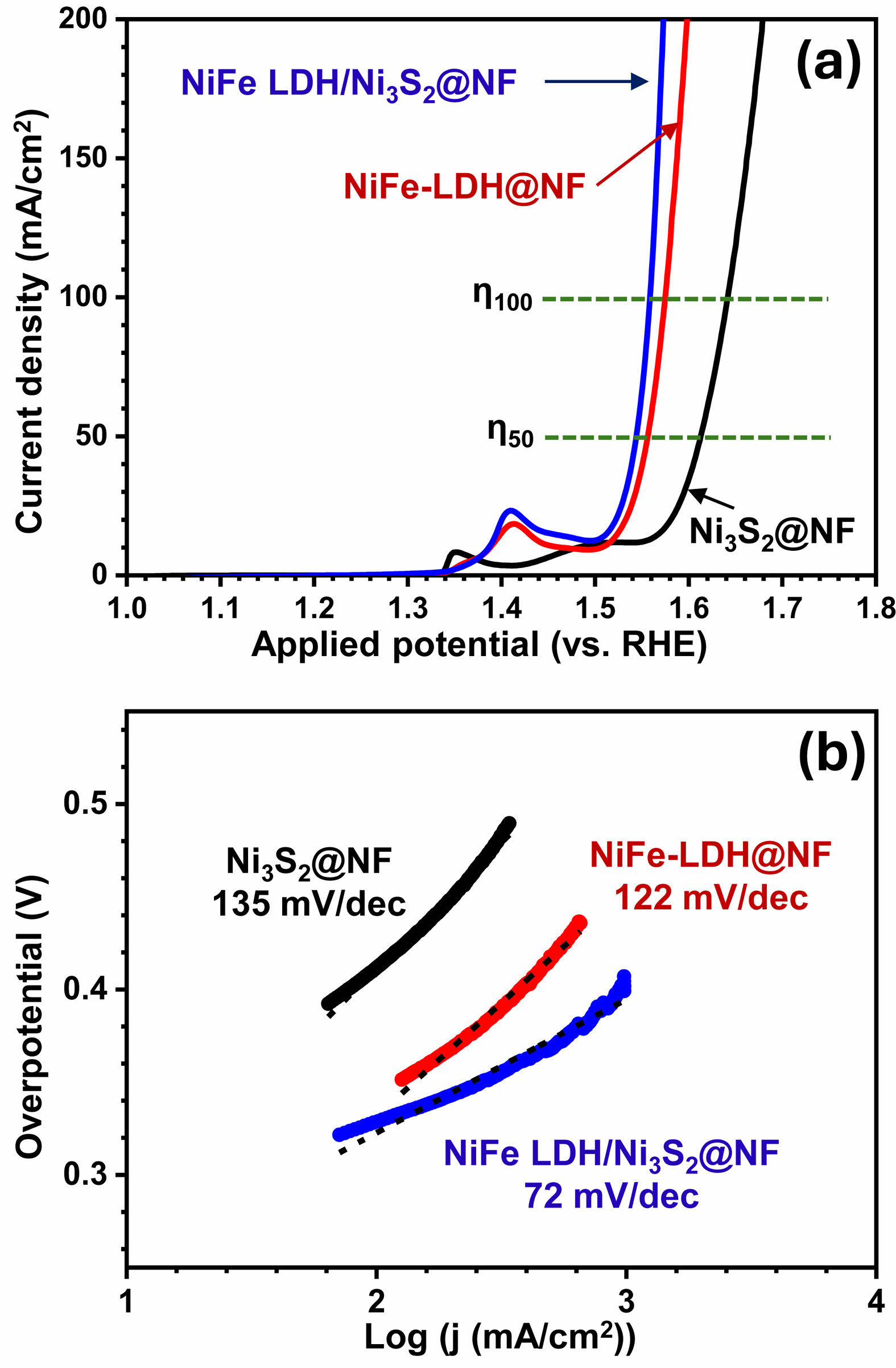
Fig. 4a compares the linear sweep voltammetry (LSV) curves of the Ni3S2@Ni-foam, NiFe-LDH@Ni-foam, and NiFe-LDH/Ni3S2@Ni-foam electrodes in 1.0 M KOH. All potentials are referred to the reversible hydrogen electrode (RHE). To ensure a fair and thermodynamically consistent comparison, we report overpotential (η) at 50 and 100 mA·cm-2 rather than at 10 mA·cm-2. First, the 10 mA·cm-2 region can overlap with the Ni²⁺/Ni³⁺ oxidation (~1.3–1.4 V vs. RHE), where redox/capacitive currents are often misinterpreted as OER activity, leading to artificially low overpotentials—a widely noted source of error in recent literature [21]. Second, because liquid-electrolyte water electrolysis at ambient conditions carries an inevitable ~0.25 V overhead, credible datasets at 10 mA·cm-2 typically cluster around 250 ± 50 mV; evaluating at higher current densities minimizes onset/definition artifacts and more robustly reflects intrinsic kinetic and transport characteristics [21]. Third, reporting η at ≥ 50 mA·cm-2 aligns with application-relevant metrics: industrially meaningful electrodes are engineered to sustain hundreds to thousands of mA·cm-2 at low η with durability, so 50 and 100 mA·cm-2 serve as practical bridge points that enable fairer literature comparison focused on high current-density operation [22].
The Ni3S2@Ni-foam electrode requires relatively high overpotentials of 385 mV at 50 mA·cm-2 and 412 mV at 100 mA·cm-2, indicating moderate OER activity. In contrast, the NiFe-LDH@Ni-foam sample shows significantly lower overpotentials of 330 mV (50 mA·cm-2) and 345 mV (100 mA·cm-2), demonstrating that the incorporation of Fe into the Ni hydroxide lattice enhances the intrinsic catalytic activity. Remarkably, the hierarchical NiFe-LDH/Ni3S2@Ni-foam electrode exhibits the best OER performance with overpotentials as low as 315 mV at 50 mA·cm-2 and 325 mV at 100 mA·cm-2. This large reduction in the required potential clearly highlights the synergistic effect between the highly conductive Ni3S2 support and the catalytically active NiFe-LDH nanosheets. In particular, the potential difference between 50 and 100 mA·cm-2 is smallest for the NiFe-LDH/Ni3S2@Ni-foam sample, indicating a fast reaction kinetics and superior charge-transfer capability in the high-current region.
The catalytic kinetics of the samples were further evaluated by the corresponding Tafel plots (Fig. 4b). The Tafel slope of Ni3S2@Ni-foam is 135 mV/dec, which is greatly reduced to 122 mV/dec for NiFe-LDH@Ni-foam. Notably, the NiFe-LDH/Ni3S2@Ni-foam electrode shows the lowest Tafel slope of 72 mV dec⁻¹, suggesting the most favorable OER reaction kinetics. The much lower Tafel slope and overpotential of the heterostructured sample can be ascribed to the intimate interfacial contact between NiFe-LDH and Ni3S2, which promotes more efficient charge transport and accelerates the generation of the active oxyhydroxide species under anodic polarization [23]. These results demonstrate that the rational integration of NiFe-LDH on conductive Ni3S2 enables a synergistic enhancement of catalytic activity, thereby leading to superior OER performance compared with the individual components.
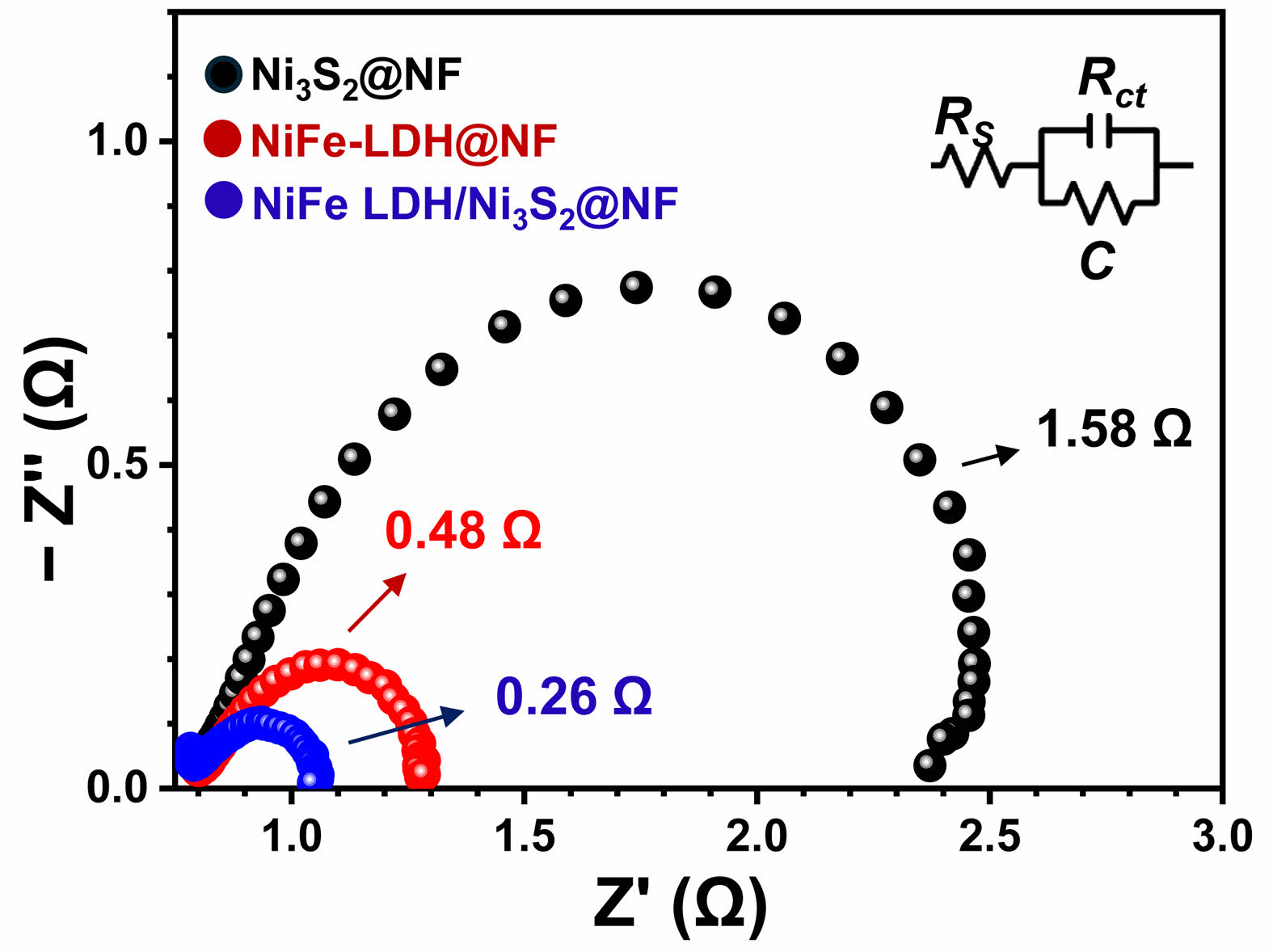
Electrochemical impedance spectroscopy (EIS) was employed to gain insight into the charge-transfer kinetics of the as-prepared electrodes. Fig. 5 displays the Nyquist plots of Ni3S2@Ni-foam, NiFe-LDH@Ni-foam, and NiFe-LDH/Ni3S2@Ni-foam collected at the same overpotential in 1.0 M KOH. In all cases, the impedance spectra consist of a depressed semicircle in the high-frequency region, corresponding to the charge-transfer resistance (Rct) at the electrode–electrolyte interface. The Ni3S2@Ni-foam sample exhibits a relatively large semicircle, indicating a high Rct value and thus a sluggish electron-transfer process. When NiFe-LDH is directly grown on Ni foam (NiFe-LDH@Ni-foam), the diameter of the semicircle is clearly reduced, suggesting that the incorporation of Fe into the Ni hydroxide lattice improves the intrinsic conductivity and facilitates the interfacial charge transfer [24]. Remarkably, the hierarchical NiFe-LDH/ Ni3S2@Ni-foam electrode displays the smallest semicircle diameter among the three samples, revealing the lowest Rct. This indicates that the hybrid structure offers a faster electron-transfer pathway owing to the intimate contact between the highly conductive Ni3S2 nanosheets and the catalytically active NiFe-LDH layer. These results are in good agreement with the LSV and Tafel data (Fig. 4) as well as the Cdl/ECSA results (Fig. 6), and clearly demonstrate that the formation of a NiFe-LDH/Ni3S2 heterointerface not only increases the number of active sites but also significantly promotes interfacial electron transfer, which synergistically contribute to the superior OER performance of the hierarchical electrode [25].
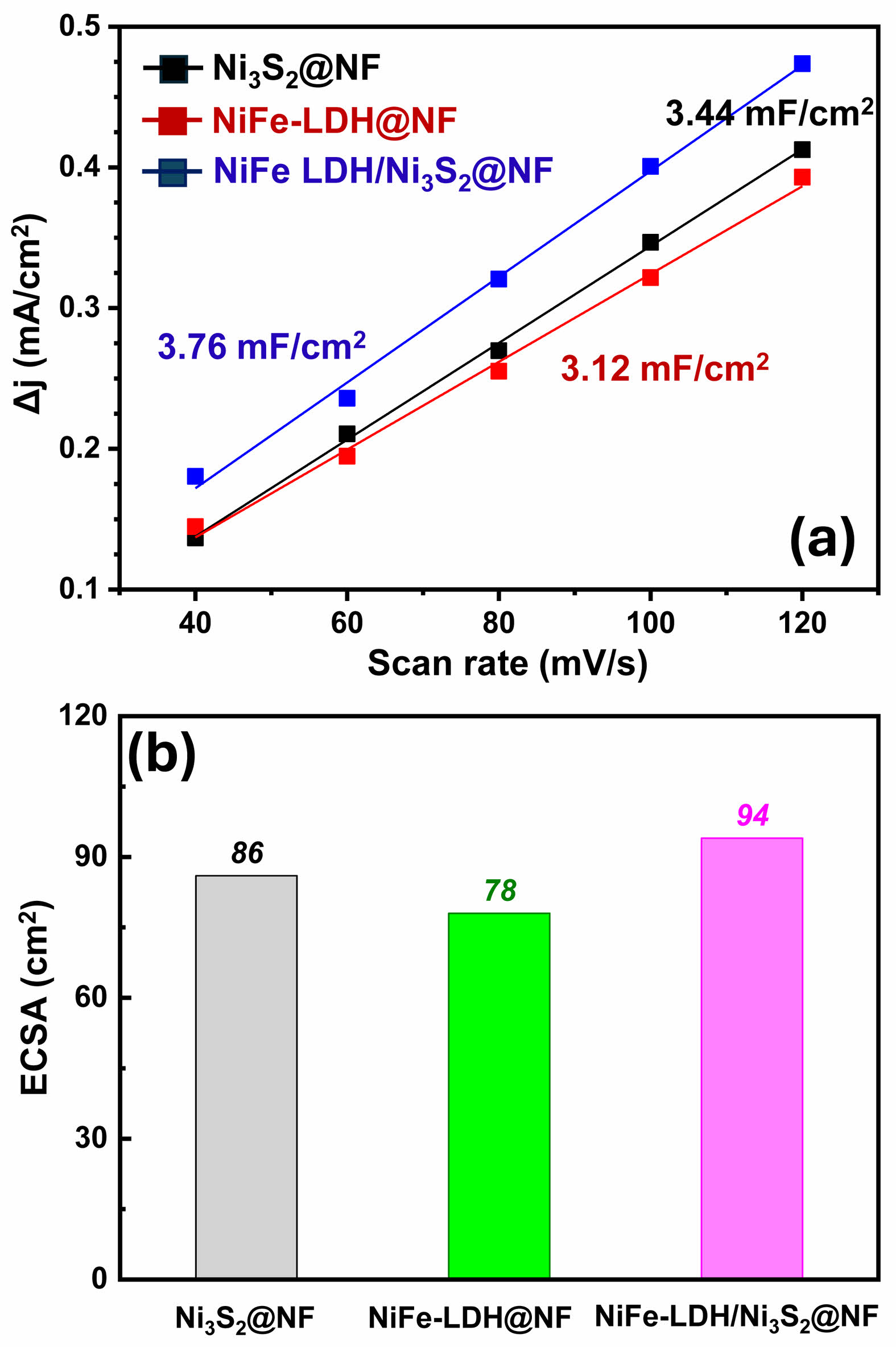
The electrochemically active surface area (ECSA) of the prepared electrodes was further evaluated by measuring the double-layer capacitance (Cdl) in the non-Faradaic region. As summarized in Fig. 6a, the Ni3S2@Ni-foam sample exhibits a Cdl value of 3.44 mF·cm-2, indicating that the surface of the sulfide layer provides a moderate number of electrochemically accessible active sites. Interestingly, the NiFe-LDH@Ni-foam sample shows a slightly lower Cdl value of 3.12 mF·cm-2, which can be attributed to the relatively loose and partially aggregated morphology of the NiFe-LDH nanosheets grown directly on the surface of the Ni foam. In contrast, the NiFe-LDH/Ni3S2@Ni-foam electrode displays the highest Cdl value of 3.76 mF·cm-2, suggesting that the hybridization of NiFe-LDH with the underlying Ni3S2 nanosheets leads to a more efficient utilization of the active surface and enables a higher degree of electrochemical exposure [26].
Using a typical specific capacitance of 40 μF·cm-2, the corresponding ECSA values were calculated (Fig. 6b). The Ni3S2@Ni-foam, NiFe-LDH@Ni-foam, and NiFe-LDH/Ni3S2@Ni-foam samples exhibit ECSA values of 86, 78, and 94 cm², respectively. In particular, the heterostructured NiFe-LDH/Ni3S2@Ni-foam electrode shows the largest ECSA, indicating the highest number of active sites available for the oxygen evolution reaction [27]. These results correlate well with the electrochemical performance shown in Fig. 4, where the NiFe-LDH/Ni3S2@Ni-foam electrode exhibited the lowest overpotential and Tafel slope. Therefore, the enhanced OER activity of the hierarchical sample can be attributed not only to its improved intrinsic catalytic activity but also to the increased number of electrochemically active sites derived from the intimate interfacial coupling between NiFe-LDH and Ni3S2.
|
Fig. 1 XRD patterns of the of the (a) Ni3S2@Ni-foam, (b) NiFeLDH@Ni-foam and (c) NiFe-LDH/Ni3S2@Ni-foam samples. |
|
Fig. 2 Highly magnified FE-SEM images and EDS data of the (a) Ni3S2@Ni-foam, (b) NiFe-LDH@Ni-foam and (c) NiFe-LDH/ Ni3S2@Ni-foam samples. |
|
Fig. 3 XPS spectra of XRD patterns of the NiFe-LDH/Ni3S2@ Ni-foam sample : (a) Ni 2p and (b) Fe 2p. |
|
Fig. 4 (a) LSV curves and (b) Tafel slopes of the Ni3S2@Ni-foam, NiFe-LDH@Ni-foam and NiFe-LDH/Ni3S2@Ni-foam samples. |
|
Fig. 5 Nyquist plots of the Ni3S2@Ni-foam, NiFe-LDH@Nifoam and NiFe-LDH/Ni3S2@Ni-foam samples. |
|
Fig. 6 (a) Cdl and ECSA of the Ni3S2@Ni-foam, NiFe-LDH@ Ni-foam and NiFe-LDH/Ni3S2@Ni-foam samples. |
In summary, a hierarchical NiFe-LDH/Ni3S2@Ni-foam heterostructure was successfully fabricated on Ni foam by sequential hydrothermal sulfurization and subsequent LDH growth. Structural and surface characterizations confirmed the coexistence of crystalline Ni3S2 and NiFe-LDH phases, while SEM and XPS analyses revealed the formation of an interconnected nanosheet network with strong interfacial coupling between the two components. The hierarchical NiFe-LDH/Ni3S2@Ni-foam electrode showed markedly enhanced OER performance compared to the individual Ni3S2@Ni-foam and NiFe-LDH@Ni-foam electrodes, as evidenced by a lower overpotential and a smaller Tafel slope. In addition, EIS and ECSA analyses indicated that the heterostructure enables more efficient charge transfer and provides a larger number of electrochemically active sites. These results clearly demonstrate that the synergistic integration of conductive sulfide scaffolds and active LDH nanosheets offers an effective route for constructing high-performance OER electrocatalysts and highlights the importance of interfacial engineering in catalyst design.
This work was supported by the National Research Foundation of Korea (NRF) grant funded by the Korean government (MSIT) (RS-2024-00342443).
- 1. F. Song and X. Hu, Nature Comm. 5 (2014) 4477.
-

- 2. W. Kang, R. Wei, H. Yin, D. Li, Z. Chen, Q. Huang, P. Zhang, H. Jing, X. Wang, and C. Li, J. Am. Chem. Soc. 145 (2023) 3470-3477.
-
- 3. H. Over, ACS Catal. 11 (2021) 8848-8871.
-
- 4. Z. Ma, Y. Zhang, S. Liu, W. Xu, L. Wu, Y. Hsieh, P. Liu, Y. Zhu, K. Sasaki, J.N. Renner, K.E. Ayers, and R.R. Adzic, J. Electroanal. Chem. 819 (2018) 296-305.
-
- 5. H.N. Nong, L. Gan, E. Willinger, D. Teschner, and P. Strasser, Chem. Sci. 5 (2014) 2955-2963.
-
- 6. M. Chatenet, B.G. Pollet, D.R. Dekel, F. Dionigi, J. Deseure, P. Millet, R.D. Braatz, M.Z. Bazant, M. Eikerling, I. Staffell, P. Balcombe, Y. Shao-Horn, and H. Schäfer, Chem. Soc. Rev. 51 (2022) 4583.
-
- 7. L. Li, X. Cao, J. Huo, J. Qu, W. Chen, C. Liu, Y. Zhao, H. Liu, G. Wang, J. Energy Chem. 76 (2023) 195-213.
-
- 8. H. Li, J. Wang, R. Qi, Y. Hu, J. Zhang, H. Zhao, J. Zhang, and Y. Zhao, Appl. Catal. B-Environ. 285 (2021) 119778.
-
- 9. W. Ou, D. Liu, X. Ye, N. Cui, and Y. Zhou, ChemSusChem 18 (2025) e202402178.
-
- 10. L. Peng, C. Wang, Q. Wang, R. Shi, T. Zhang, and G.I.N. Waterhouse, Adv. Energy Sustain. Res. 2 (2021) 2100078.
-
- 11. P. Zhang, Z. Wang, X. Hou, J. Lu, X. Xu, C. Stampfl, and C. Hu, Appl. Catal. A-Gen. 624 (2021) 118324.
-
- 12. P.M. Bodhankar, P.B. Sarawade, G. Singh, A. Vinu, and D.S. Dhawale, J. Mater. Chem. A 9 (2021) 3180-3208.
-
- 13. D. Tyndall, M.J. Craig, L. Gannon, C. McGuinness, N. McEvoy, A. Roy, M. G-Melchor, M.P. Browne, and V. Nicolosi, J. Mater. Chem. A 11 (2023) 4067-4077.
-
- 14. J. Zhang, H.B. Yang, D. Zhou, and B. Liu, Chem. Rev. 122 (2022) 17028-17072.
-
- 15. J. Wan, S. Xie, Y. Sun, W. Bi, Q. Zhou, Y. Hou, M. Yu, T. Li, D. Zhou, and B. Liu, Int. J. Hydrog. Energy 109 (2025) 813-822.
-
- 16. S. Zhang, W. Liu, Y. Zhang, Y. Song, X. Zhao, X. Du, and S. Hu, J. Alloy. Compd. 1031 (2025) 180908.
-
- 17. Y.-R. Hong, K.M. Kim, J.H. Ryu, S. Mhin, J. Kim, G. Ali, K.Y. Chung, S. Kang, and H. Han, Adv. Fuct. Mater. 30 (2020) 2004330.
-
- 18. H. Han, K.M. Kim, J.H. Ryu, H.J. Lee, J. Woo, G. Ali, K.Y. Chung, T. Kim, S. Kang, S. Choi, J. Kwon, Y.-C. Chung, S. Mhin, and T. Song, Nano Energy 75 (2020) 104945.
-
- 19. B.M. Hunter, W. Hieringer, J.R. Winkler, H.B. Graya, and A.M. Müller, Energy Environ. Sci. 9 (2016) 1734.
-
- 20. H. Lei, L. Ma, Q. Wan, S. Tan, B. Yang, Z. Wang, W. Mai, and H.J. Fan, Adv. Energy Mater. 22 (2022) 2202522.
-
- 21. P. Trivedi, N.C. Minj, S. Mittal, B. Kamaraj, S. Yadav, and A. Sengeni, J. Mater. Chem. A 13 (2025) 21436.
-
- 22. V.R. Jothi, K. Karuppasamy, T. Maiyalagan, H. Rajan, C.-Y. Jung, and S.C. Yi, Adv. Energy Mater. 10 (2020) 1904020.
-
- 23. N. Zhou, Q. Wang, J. Zhu, N. Zhou, X. Chai, M. Li, Z. Pei, K. Hu, Z. Huang, and B. Chen, Mater. Today Chem. 43 (2025) 102510.
-
- 24. C. Li, T. Yang, J. Fan, E. Liu, B. Zhao, and T. Su, J. Alloy. Compd. 970 (2024) 172710.
-
- 25. D. Deng, Q. Li, W. Zhang, H. Li, and L. Xu, Inorg. Chem. 63 (2024) 20022-20029.
-
- 26. S.-W. Wu, S.-Q. Liu, X.-H. Tan, W.-Y. Zhang, K. Cadien, and Z. Li, Chem. Eng. J. 442 (2022) 136105.
-
- 27. S.S. Jeon, P.W. Kang, M. Klingenhof, H. Lee, F. Dionigi, and P. Strasser, ACS Catal. 13 (2023) 1186-1196.
-
 This Article
-
2025; 26(5): 796-802
Published on Oct 31, 2025
- 10.36410/jcpr.2025.26.5.796
- Received on Aug 19, 2025
- Revised on Sep 11, 2025
- Accepted on Oct 2, 2025
Services
- Abstract
introduction
experimental
results and discussion
conclusion
- Acknowledgements
- References
- Full Text PDF
Shared
Correspondence to
- Jeong Ho Ryu
-
Department of Materials Science and Engineering, Korea National University of Transportation, Chungju, 50 Daehak-ro, Chungju, Chungbuk 27469, South Korea
Tel : +82-43-841-5384 Fax: +82-43-841-5380 - E-mail: jhryu@ut.ac.kr
Clean-Energy Research Institute(CRI), Hanyang University, 222, Wangsimni-ro, Seongdong-gu, Seoul, 04763, Korea
E-mail: jcpr@hanyang.ac.kr