


- Properties of nickel ferrite ceramics obtained by combustion synthesis and two-step sintering, and their detection of LPG in air
Nihafini Kasor, Methee Promsawat and Tawat Chanadee*
Materials Science Program, Division of Physical Science, Faculty of Science, Prince of Songkla University (PSU), Hat Yai, Songkhla 90110, Thailand
This article is an open access article distributed under the terms of the Creative Commons Attribution Non-Commercial License (http://creativecommons.org/licenses/by-nc/4.0) which permits unrestricted non-commercial use, distribution, and reproduction in any medium, provided the original work is properly cited.
Nickel ferrite (NiFe2O4) ceramics were prepared by combustion in air and sintered using different two-step sintering processes, classified as condition I and condition II. Both conditions employed a first-step temperature (T1) of 1200 °C for 1 minute. In the second step, the temperature (T2) was reduced to 1150 °C, with no holding time for condition I and a 240-minute hold for condition II. XRD analysis confirmed the formation of a single-phase NiFe2O4 with no phase transformations during sintering. NiFe2O4 ceramic from condition II exhibited higher density (3.71 ± 0.04 g/cm3) and flexural strength (17.32 ± 0.52 MPa) than those from condition I (3.43 ± 0.06 g/cm3 and 10.19 ± 0.83 MPa). Despite an 8% increase in density and an 11.68% reduction in porosity, the strength improved by ~52%, highlighting the role of extended holding time. However, the higher porosity and specific surface area (0.76 m²/g) of NiFe2O4 ceramic from condition I enhanced gas-sensing properties. The NiFe2O4 ceramics responded consistently to variations in LPG flow rate, indicating p-type semiconductor behavior. Ceramic from condition I showed stronger and faster responses to LPG at room temperature (S = 0.76, t90 = 20.47 s, trec = 1.29 min) than ceramic sintered from condition II (S = 0.46). The sensitivity of the ceramic from condition I at various LPG concentrations was 7.31 × 10⁻⁶ ppm-1.
Keywords: Nickel ferrite, Combustion synthesis, Two-step sintering, P-type semiconductor, Gas sensor.
Nickel ferrite (NiFe2O4) is a spinel-type oxide that conforms to the general formula of AB2O4 with Fe3+ ions equally distributed between the A sites (tetrahedral) and B sites (octahedral), and Ni2+ ions occupying only the B sites. NiFe2O4 is a soft magnetic material that displays ferromagnetic behavior and high electrical resistivity [1,2]. It is suitable for ceramic applications that require high density, such as magnetic or electrical devices. However, for applications such as gas sensing, materials with low density (i.e. porous materials) and a large surface area are preferred. Nonetheless, NiFe2O4 is a promising metal oxide semiconductor (MOS) for gas sensors. Due to its magnetic behavior, NiFe2O4 can be used at room temperature, unlike other MOS materials, such as tin oxide (SnO2), zinc oxide (ZnO) and tungsten oxide (WO3), which require elevated temperatures to achieve high sensitivity [1]. This difference is a practical advantage for gas sensing, as removing the need for a heating system avoids the risk of overheating, which can cause electrical short circuits. Furthermore, the moderate band gap energy of bulk NiFe2O4 (~2-3 eV) allows sufficient carrier activation at, or slightly above, room temperature when gas molecules adsorb onto the sensing surface [3, 4]. A sensor based on NiFe2O4 demonstrated a good response to liquefied petroleum gas (LPG) [31], which is widely used as a fuel in households, and various commercial and industrial settings.
Various synthesis methods have been developed to prepare NiFe2O4, including wet-chemistry techniques (such as solution combustion, sol-gel, co-precipitation, and hydrothermal) and solid-state reactions followed by high-temperature heat treatment [5, 6]. Combustion synthesis is a solid-state technique that involves an exothermic, self-sustained chemical reaction between reactants and fuels. The advantages of this method include its simplicity, energy efficiency, and short processing time. At room temperature, only a small amount of external ignition energy is required to initiate the reaction. The combustion then generates extreme exothermic heat, allowing the reaction to be self-sustaining. At the end of the combustion reaction, the rapid cooling rate permits the formation of solid materials with very fine grains and metastable compositions [5,7]. The technique is currently used to produce advanced ceramic materials.
Porous ceramics are widely used in industrial, catalytic, environmental, and safety applications including gas sensors, where performance is closely linked to surface characteristics. Several methods of preparing porous ceramics are available. One method involves impregnating a porous polymeric sponge with ceramic slurry. A commonly used and simple method involves partial sintering. The porosity of porous ceramics depends on the particle size of the green body and the sintering technique used [8]. Two-step sintering (TSS) is also a simple approach and produces high-density materials without applying external pressure. Previous studies have reported that TSS produces ceramics with higher density and smaller grain size than conventional sintering, which uses a constant heating ramp rate with a holding time at the sintering temperature [9-12]. TSS involves two steps: first the green sample is heated from room temperature to a high temperature (T1) with a short holding time close to zero (t1). Then, the sample is cooled rapidly to a lower temperature (T2) between 50 and 150 °C below T1, and held at T2 for a longer period (t2) [13, 14]. The fast cooling rate in this technique suppresses accelerated grain growth by structural freezing while allowing densification. This phenomenon occurs due to the diffusion of atoms, and grain boundary migration during sintering is thought to occur independently of this diffusion [8, 15]. Therefore, TSS can be used to control the porosity of ceramic products.
In the present work, NiFe2O4 powder was synthesized by combustion synthesis in air. The as-synthesized NiFe2O4 powder was used to produce NiFe2O4 ceramics using TSS with different sintering conditions. The microstructures and phase compositions of the products were characterized, and the physical, magnetic, and mechanical properties were investigated. LPG was used as a representative reducing gas for evaluating the gas-sensing properties of the sintered products.
Synthesis of NiFe2O4 powder
The synthesis procedure for NiFe2O4 was adapted from a previous work [7]. Commercially available reactant powders from Sigma-Aldrich included iron (III) oxide (Fe2O3, 99%), nickel oxide (NiO, 99%), and iron (Fe, 99%). Sodium perchlorate (NaClO4, 97%) from Alfa Aesar was used as the exothermic fuel. The reactant and fuel powders with a molar ratio of 1:0.5:1:0.1, were dry-mixed to homogenously by ball milling for 2 h in a nylon vial using zirconia balls. Twenty grams of mixed powders were compacted to form a cylindrical sample with a diameter of 25.4 mm, a length of 25 mm and 50-60% of the theoretical density. To initiate the combustion reaction, the sample was ignited in air using a high-temperature oxygen-acetylene flame. The setup apparatus used in this experiment followed the procedure outlined in [16]. The as-combusted porous product was allowed to cool to room temperature, and then mechanically broken and ground into a friable powder with a zirconia mortar and pestle. The powder was washed several times with deionized water (DI) to remove the NaCl by-product and filtered using no. 41 filter paper assisted by a suction pump. Finally, the washed powder was dried in a hot air oven at 100°C for 24 h to obtain the as-synthesized NiFe2O4 powder.
Fabrication of NiFe2O4 ceramic by two-step sintering
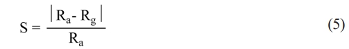
Prior to the sintering process, the as-synthesized NiFe2O4 powder was high-energy milled for 2h by planetary ball milling (Fritsch GmbH, Pulverisette 6) with a WC-Co jar and milling balls at 400 rpm. The milled NiFe2O4 powder was sieved to obtain fine particles with a size less than 45 μm. A total of 0.8 g of milled-NiFe2O4 powder was mixed with 0.1mL of 3wt% polyvinyl alcohol (PVA) solution and then hydraulically pressed (Krumor, HP-900) under 2000 psi, to form a cylindrical green pellet with a diameter of 10 mm and a thickness of 5 mm. The green pellet was sintered using TSS in air in a muffle furnace (Carbolite, RHF 16/8). Two different temperature profiles were applied: condition I and condition II. A debinding step was first applied to remove the organic binder. In condition I, the pellet was heated to T1 (1200 °C) at a rate of 10 °C/min and held at this temperature for 1 min (t1). The temperature was then reduced at a cooling rate of 20 °C/min to T2 (1150°C), with no holding time. In condition II, the initial sintering step was the same as in condition I. However, at T2, the sample was held for 240 min (t2). The temperature profiles of the TSS processes are presented in Fig. 1.
Characterizations
The morphologies of the as-sintered NiFe2O4 ceramics, both at the surface and cross-section, were characterized using a scanning electron microscope (SEM, Quanta, FEI 400). The grain size was determined using the ImageJ program (v1.53e) and calculated based on the line intercept method according to the ASTM E112. Phases in the samples were identified by X-ray diffractometer (XRD, PANalytical, Empyrean) using Cu-Kα radiation. Specific surface area, pore volume, and pore size were measured by the Brunauer, Emmett, and Teller method (BET, Micromeritics, ASAP2460) using single-point adsorption at -195.850°C, with nitrogen (N2) gas as the adsorptive.
Physical properties
Based on Archimedes’ principle, NiFe2O4 ceramics were soaked in boiling distilled water for 5h and then immersed in distilled water at room temperature for an additional 8h. Afterwards, the ceramics were hydrostatically weighed with a precision analytical balance (Sartorious, B5A224S-CW). The sintered density and apparent porosity of the NiFe2O4 ceramics were calculated according to Eq. (1) and (2) [17]:
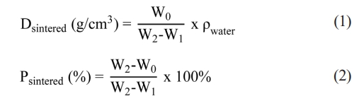
where Dsintered is the sintered density and Psintered is the apparent porosity, W0, W1, W2 are the dry weight of the specimen, the weight in water of the water-saturated specimen, and the weight in air of the water-saturated specimen, respectively. ρwater is the density of water (1 g/cm3). In addition, the linear shrinkage of NiFe2O4 ceramics was evaluated using Eq. (3) [8]:
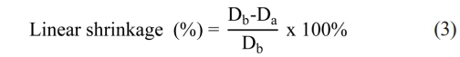
where Db and Da denote the diameters of ceramic samples before and after sintering, respectively.
Mechanical strength
The mechanical strength of the NiFe2O4 ceramics was tested using biaxial flexure on a universal testing machine (UTM, Shimadzu, AGX-V) at a crosshead speed of 0.5 mm/min, in accordance with ISO/DIS 6872: 2013(E) standards. Discs of NiFe2O4 ceramics were prepared to meet the specified minimal thickness of 1.2 ± 2 mm with diameters ranging from 12 to 16 mm. Each sample was placed on three hardened steel ball supports, and the load was applied using a flat punch with a diameter of 1.5 mm. The biaxial flexural strength was then calculated using Eq. (4) [17]:
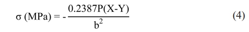
where σ is biaxial flexural strength (or the maximum tensile stress), Pis the load at failure, and bis the specimen thickness at the fracture origin. X and Y were determined using the following formulas:
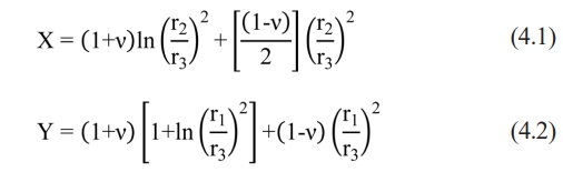
in which is Poisson’s ratio (0.25 for ceramics), r1 is the radius of the support circle (1.6 mm), r2 is the radius of the loaded area (0.8 mm), and r3 is the radius of the sample.
Magnetic properties
Using a vibrating sample magnetometer (VSM, LakeShore 7404), the as-sintered NiFe2O4 ceramics were characterized at room temperature in a magnetic field ranging from -10000 to 10000 Oe. The magnetic measurements included the hysteresis curve, saturation magnetization (Ms), magnetic remanence (Mr), and coercivity (Hc).
Gas-sensing properties
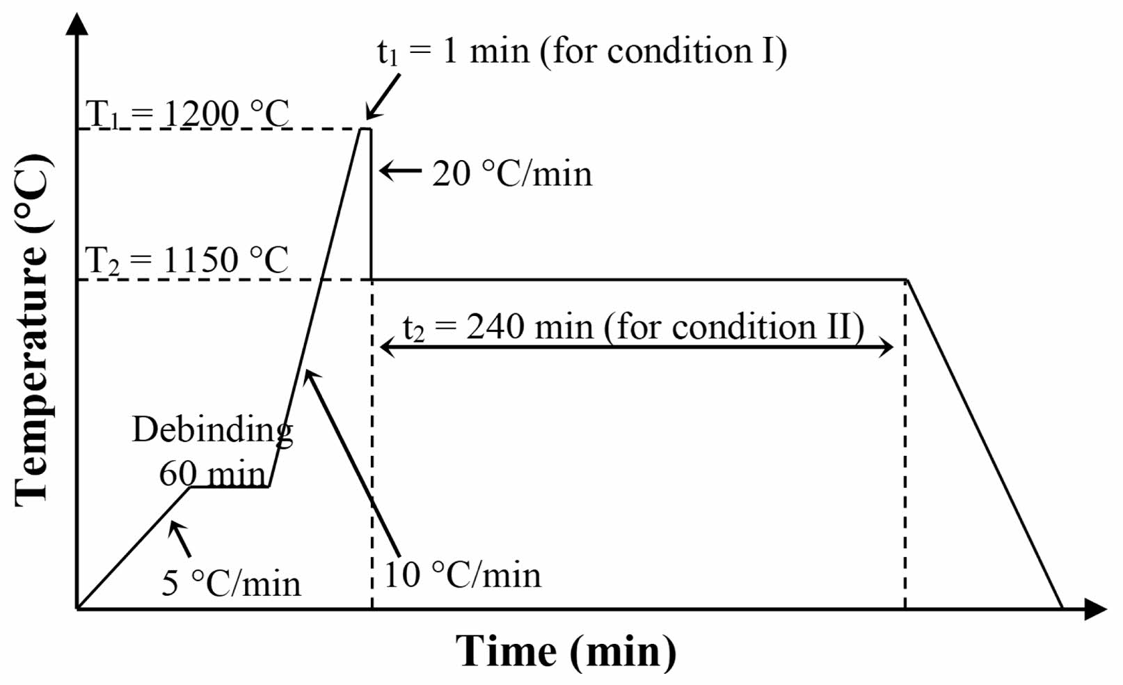
Electrodes were prepared by applying a conductive silver (Ag) paste (MG Chemicals) to both parallel surfaces of ceramic samples from both sintering conditions. The sample was placed in a cylindrical stainless-steel chamber in the presence of LPG, at room temperature (27°C) and 70% relative humidity (measured with a Barigo hygrometer). Pre-determined flow rates of LPG and air zero (AZ) gases were fed into the chamber. The flow rates of both gases were controlled by DPC mass flow controllers (Aalborg, DPC17) to adjust their ratio. The samples were exposed to LPG for 5 min at flow rates ranging from 0 to 2.0 mL/min. The electrical resistance of the sample was measured using a digital multimeter (Keysight, 34465A). The setup of the gas response measurement unit is shown in Fig. 2.
The gas response (S) of the NiFe2O4 sensor was determined by the change in electrical resistance and calculated using Eq. (5) [18]:
where Ra and Rg are the resistances of the samples in air and in LPG, respectively. The response time (t90) was defined as the time required for a 90% change from the initial resistance to a stable resistance value upon exposure to LPG. The recovery time (trec) was the time required for the resistance to return to 90% of its initial value after the removal of LPG from the chamber.
|
Fig. 1 Temperature profiles used for the fabrication of NiFe2O4 ceramics by two-step sintering. |
|
Fig. 2 Diagram showing the gas response measurement unit for NiFe2O4 ceramics. |
Characteristics of NiFe2O4 powder prepared by combustion synthesis
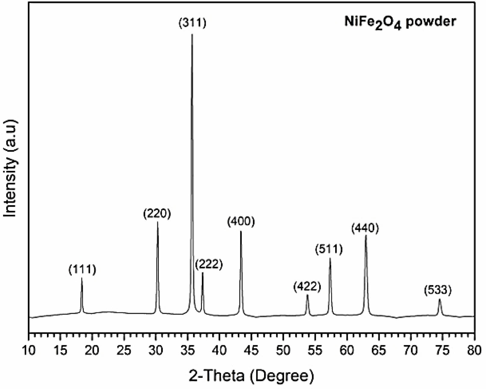
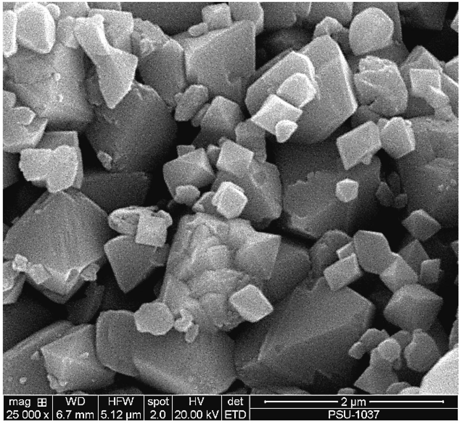
The XRD pattern of NiFe2O4 in Fig. 3 shows the position of diffraction peaks along with the corresponding crystallographic planes. The pattern confirmed the formation of a pure spinel NiFe2O4 crystal structure (space group: Fd-3m), in accordance with the ICDD powder diffraction file (PDF No. 01-086-2267). The SEM image in Fig. 4 reveals that the NiFe2O4 powder from combustion synthesis comprised octahedron particles smaller than 2 µm.
Characteristics and properties of NiFe2O4 ceramics fabricated by two-step sintering
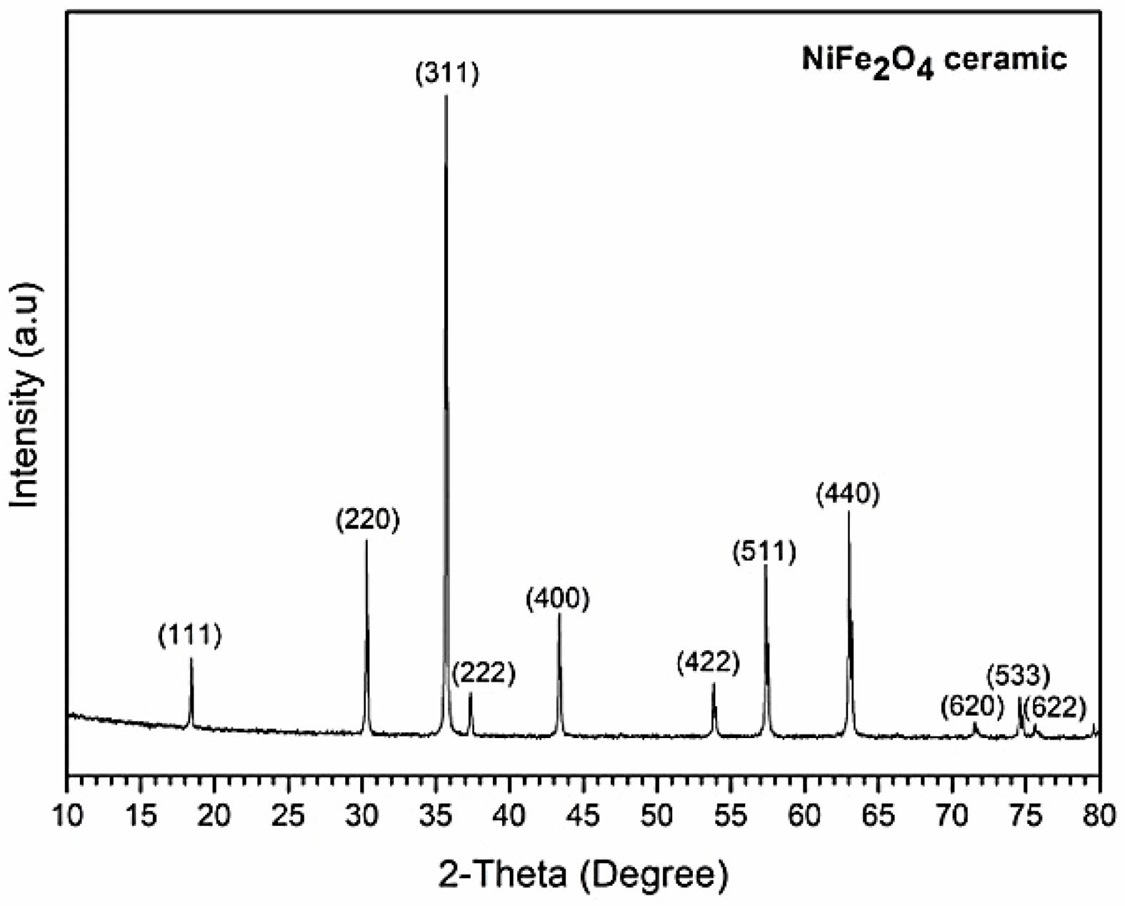
The XRD pattern (Fig. 5) of the NiFe2O4 powder processed by TSS indicated that no phase transformation had occurred, and no secondary phases had formed during sintering.
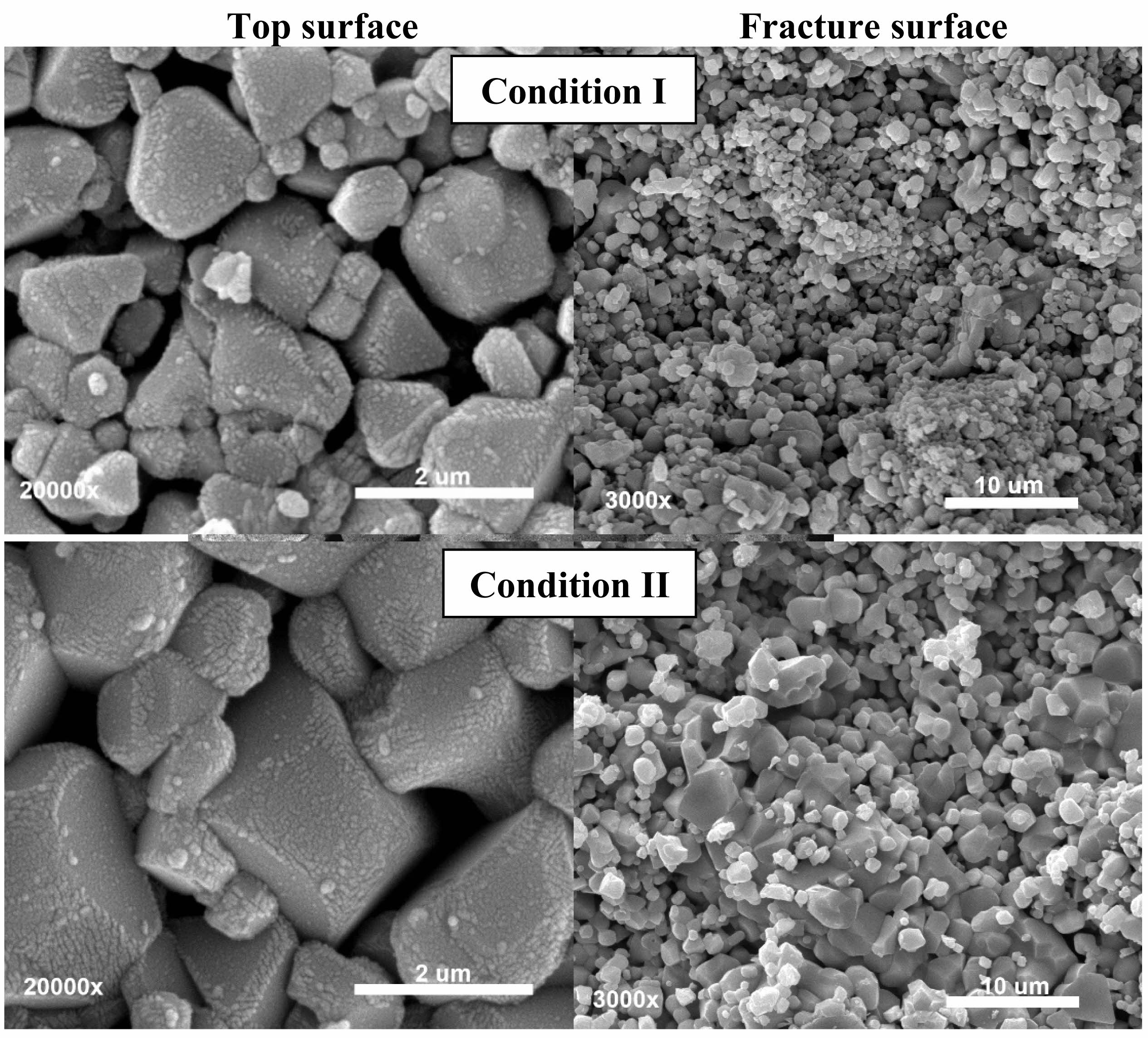
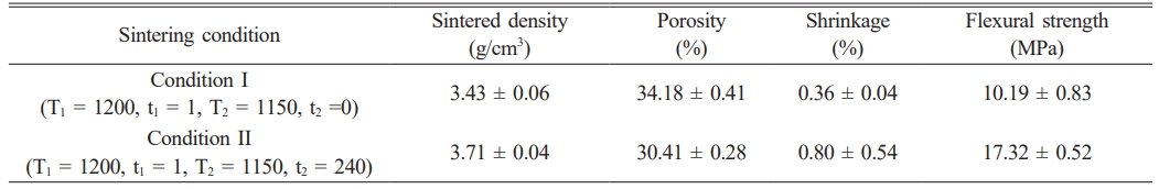
The microstructures of the NiFe2O4 ceramics from different sintering conditions were observed using SEM (Fig. 6). The SEM images revealed that the average grain size of the ceramic sintered under condition I was 0.86±0.06 µm, while the average grain size of the ceramic sintered under condition II was 1.26±0.15 µm. In condition I, there was no holding time for step 2 (t2=0), which prevented atomic diffusion, thereby suppressing grain growth and resulting in a smaller grain size. The sintered density, porosity, shrinkage and flexural strength of the sintered ceramic samples are listed in Table 1. The NiFe2O4 ceramic from condition II, which was sintered with a t₂ = 240 min, exhibited a higher flexural strength (17.32±0.52 MPa) than the NiFe2O4 ceramic from condition I (10.19±0.83 MPa). Although sintering under condition II increased the grain size, the high sintered density (3.43±0.06 g/cm3) of this ceramic was accompanied by a lower porosity (30.41 ± 0.28% compared with 34.18 ± 0.41%) and an increase in shrinkage (0.80±0.54% compared with 0.36±0.04%) that played major roles in enhancing the flexural strength of the ceramic.
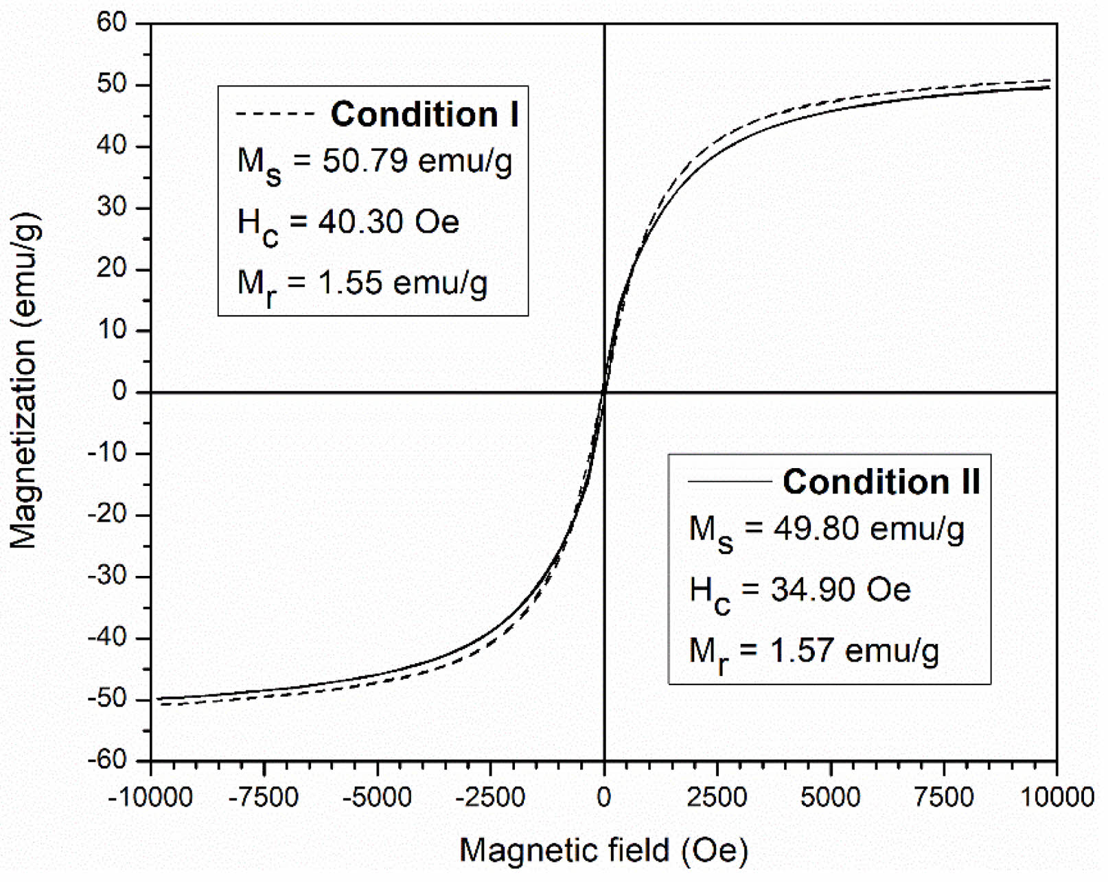
The hysteresis loop of both ceramics was measured at room temperature. The hysteresis loops indicated typical soft magnetism and the measured key values, including saturation magnetization (Ms), remanent magnetization (Mr), and coercivity (Hc), confirmed the magnetic behavior of the fabricated ceramics (Fig. 7). Both ceramics displayed Ms values (50.79 and 49.80 emu/g) that were close to that of bulk NiFe2O4 (51 emu/g) [5]. The magnetic behaviors of both NiFe2O4 ceramics enable the gas sensors to operate effectively and provide sensitive detection at room temperature, unlike conventional MOS sensors, which typically require elevated temperatures to activate adsorption and desorption processes [19-21]. In particular, the magnetic properties of the obtained NiFe2O4 ceramic can facilitate gas-solid interactions, thereby enhancing gas-sensing performance even at room temperature. These magnetic characteristics can promote the separation of charge carriers (electrons and holes), resulting in a greater number of free carriers participating in surface reactions with gas molecules. Moreover, they can enhance surface reactivity through localized magnetic fields that modulate the electronic band structure at the surface and reduce the activation energy required for the adsorption and reaction of gas molecules [32-34].
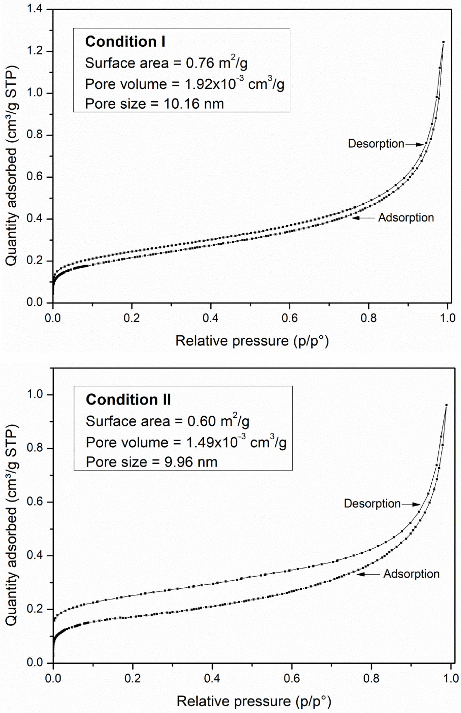
N2 adsorption and desorption isotherms were analyzed to determine the pore volume and pore size data of the NiFe2O4 ceramics sintered under both conditions. The isotherms exhibited hysteresis loops during the desorption process and were classified as type IV isotherms (Fig. 8). The disparity between adsorption and desorption is a phenomenon characteristic of ink-bottle-shaped pores, where some gas has difficulty escaping through a narrow neck during desorption. The narrower loop observed in condition I is indicative of delayed capillary condensation during adsorption [22]. According to IUPAC references, type IV isotherms are characteristic of mesoporous adsorbents with a pore diameter larger than 4 nm [22]. The results indicated pore sizes of 10.16 nm and 9.96 nm for ceramics sintered in conditions I and II, respectively, strongly confirming the isotherms type and the mesoporous nature of both ceramics. In addition, the NiFe2O4 ceramic sintered under condition I exhibited a larger specific surface area (0.76 m2/g) compared to condition II (0.60 m2/g), which can enhance gas absorption and positively impact the gas response. Although the specific surface area of the obtained NiFe2O4 ceramic is relatively low, the response to LPG gas also depends on surface defects, including oxygen vacancies and cation disorder associated with their magnetic ordering. These defects can serve as active sites for gas adsorption, thereby facilitating surface redox reactions that drive the sensing signals [35].
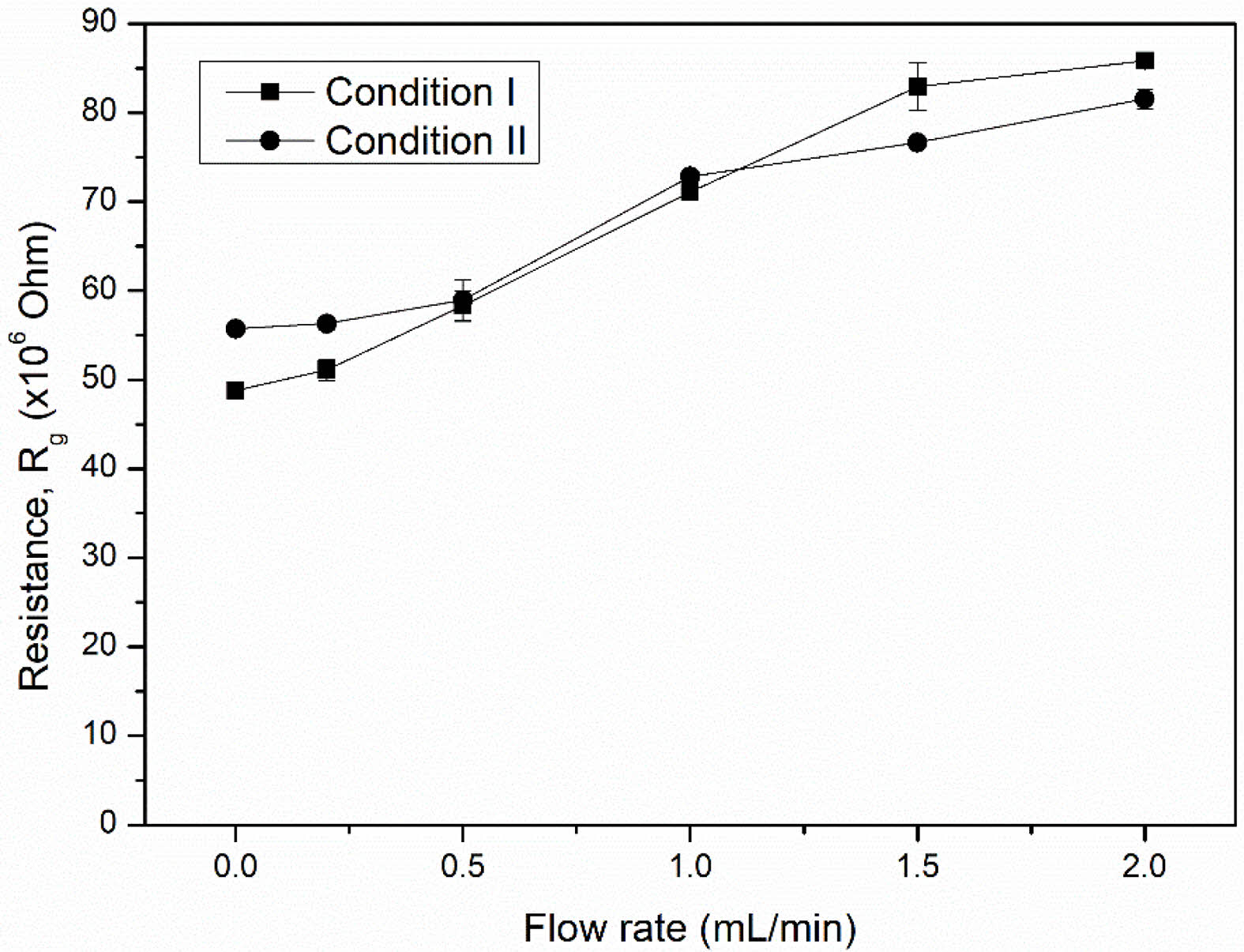
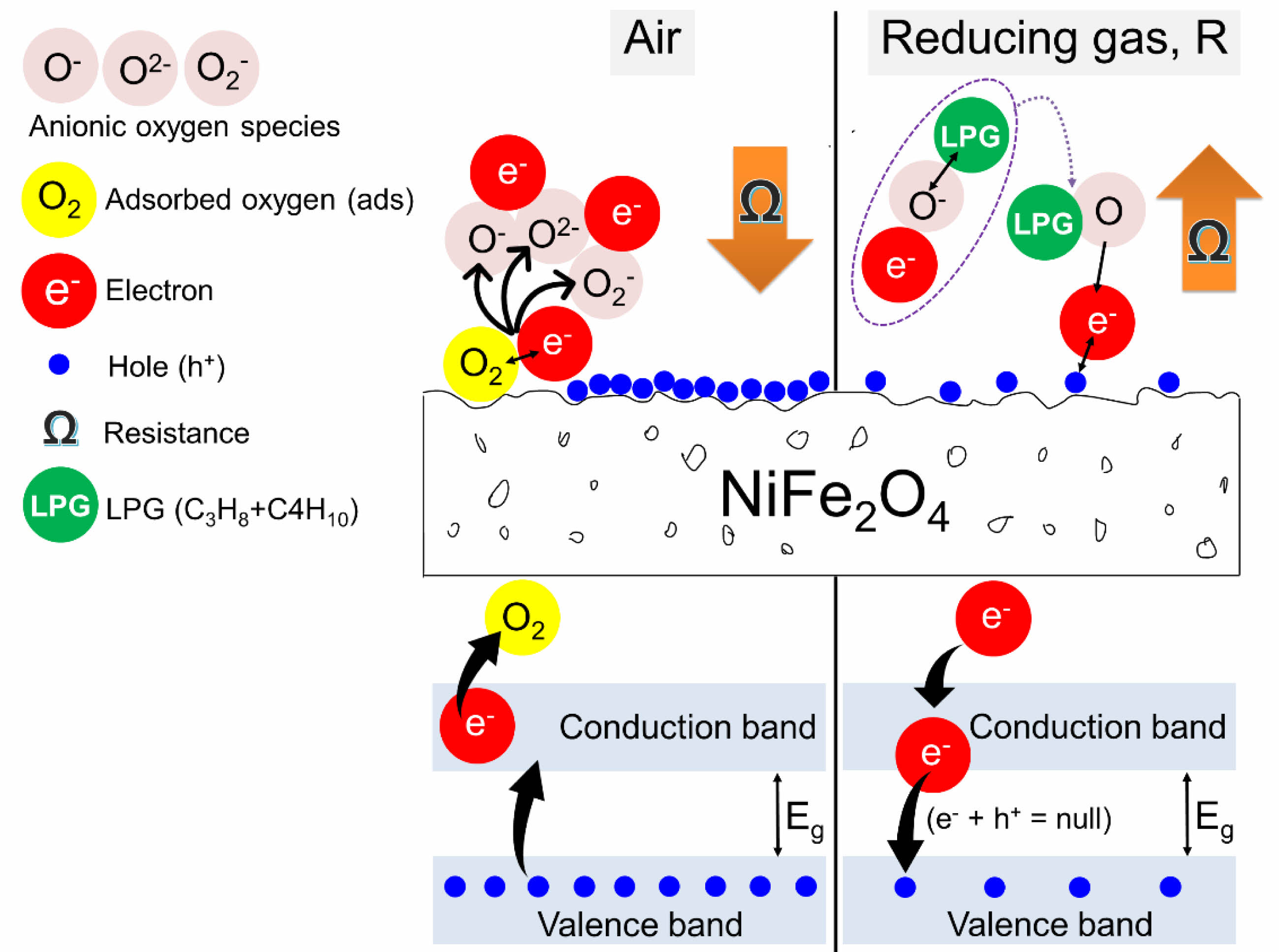
The room temperature resistance (Rg) of both NiFe2O4 ceramics was characterized by exposure to LPG at various flow rates. It was found that the Rg of both ceramics increased with the LPG flow rate (Fig. 9). The increase in resistance under reducing LPG exposure indicated that both NiFe2O4 ceramics should be classified as p-type MOS, where holes (h+) are the main conductive charge carriers. Changes in the resistance of the sensor can be explained by a surface-controlled process mechanism, as described in reactions (6) - (10), along with the schematic shown in Fig. 10. In air, oxygen molecules (O2(gas)) are most readily adsorbed (O2(ads)) on the surface of the NiFe2O4 sensor through physisorption (reaction (6)). The adsorbed oxygen molecules are ionized to form various anionic oxygen species (O2−, O−, or O2−) by capturing localized free electrons (e-) near the surfaces of NiFe2O4 molecules (reactions (7)-(9)). Meanwhile, the number of holes (h+) on the sensor surface increases as electrons are excited out of the valence band, and resistance decreases. Upon exposure to a reducing gas (R), such as LPG, the oxidation process between R and the negative oxygen species (reaction (10)) causes capped electrons to be released back to the sensor surface. The electrons insert into the valence band, recombining with holes, and the reduced number of holes leads to an increase in resistance [23-27].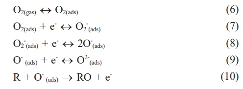
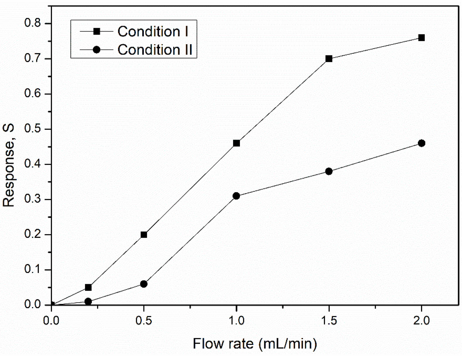
The sensing response of both NiFe2O4 ceramics was characterized by flowing LPG at room temperature from 0-2.0 mL/min (Fig. 11). The response (S) of both sensors increased depended on the LPG flow rate, peaking at 0.76 and 0.46 for the ceramics from conditions I and II, respectively. At higher LPG flow rates, the increased velocity and greater number of gas molecules reacting with adsorbed oxygen species, resulted in an enhanced sensor response [10-12].
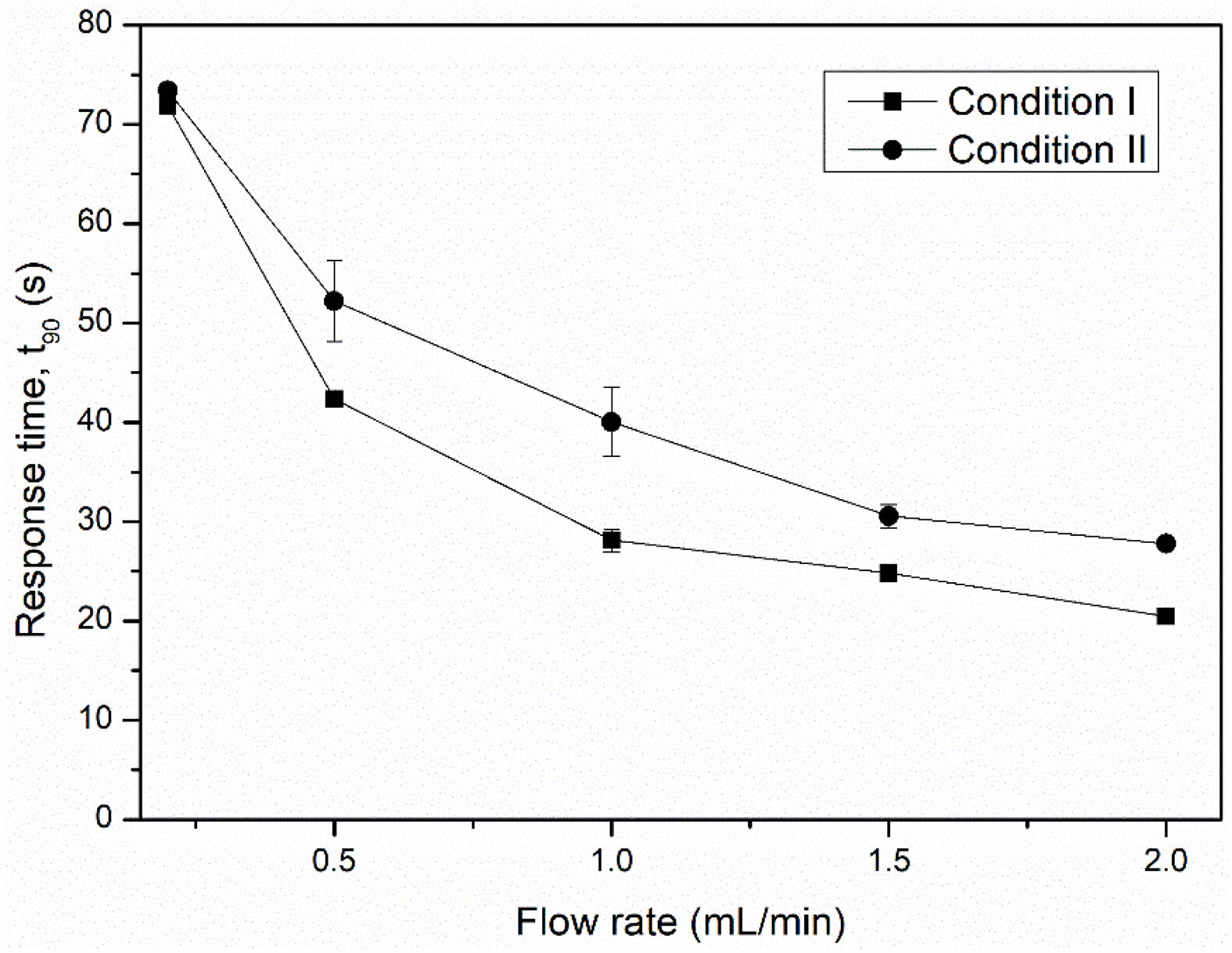
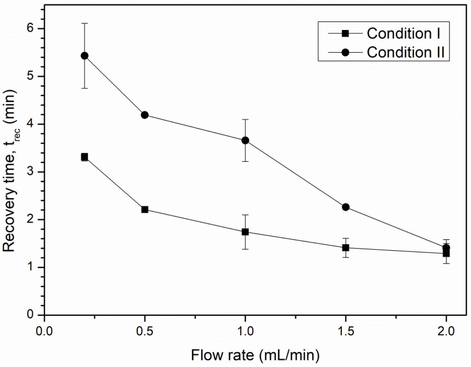
The response and recovery times are shown in Figs. 12 and 13. A higher LPG flow rate was beneficial reducing both response and recovery time. This can be explained by the increased speed of the gas molecules that allows them to more quickly adsorb to or desorb from the sensor surface. At a flow rate of 2.0 mL/min, the NiFe2O4 ceramic sensor sintered under condition I exhibited a noticeably shorter response time and faster recovery time (20.47 s and 1.29 min, respectively) than the ceramic sensor sintered under condition II (27.76 s and 1.41 min, respectively).
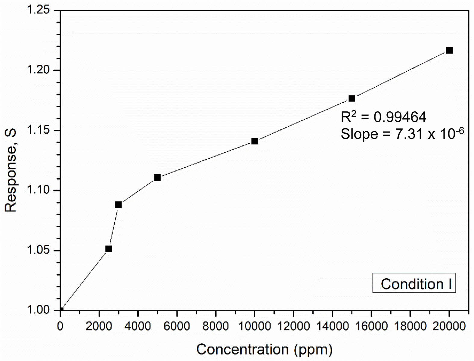
Since the gas sensing properties (response, response time, and recovery time) of the NiFe2O4 ceramic sintered under condition I were better than those of the NiFe2O4 ceramic from condition II, the former was selected for testing the sensor response at different gas concentrations. Fig. 14 shows that the sensor response of the NiFe2O4 ceramic sintered under condition I improved with increasing gas concentration, reaching a maximum value of 1.22 at 20000 ppm. The improved response was attributed to the larger amount of gas present, which increased the likelihood of adsorption at active sites on the surface. Furthermore, the sensitivity of the NiFe2O4 ceramic sensor was determined from the linear fit of the graph plotted in Fig. 14. With a correlation coefficient (R2) of 0.99464, the obtained slope value of 7.31×10⁻⁶ indicated that the fabricated ceramic sensor had a sensitivity of 7.31×10⁻⁶ ppm-1. However, since the gas sensing test in this study was conducted at room temperature under a humid environment, some water molecules may have adsorbed onto the sensor surface [29,30], potentially reducing the sensitivity of the NiFe2O4 ceramic sensor.
|
Fig. 3 XRD pattern of NiFe2O4 powder prepared by combustion synthesis. |
|
Fig. 4 SEM image of NiFe2O4 powder obtained by combustion synthesis. |
|
Fig. 5 Typical XRD pattern of NiFe2O4 ceramic fabricated by two-step sintering. |
|
Fig. 6 SEM images showing the microstructures of the top and fracture surfaces of NiFe2O4 ceramics sintered under different conditions. |
|
Fig. 7 Magnetization curves of NiFe2O4 ceramics sintered under different conditions. |
|
Fig. 8 BET isotherms of NiFe2O4 ceramics sintered under different conditions. |
|
Fig. 9 Resistance of NiFe2O4 ceramic sensors sintered under different conditions at various LPG flow rates. |
|
Fig. 10 Possible mechanisms affecting the resistance of NiFe2O4 ceramic sensors under exposure to air and LPG. |
|
Fig. 11 Responses at various LPG flow rates of NiFe2O4 ceramic sensors sintered under different conditions. |
|
Fig. 12 Response time of NiFe2O4 ceramic sensors after exposure to various LPG flow rates. |
|
Fig. 13 Recovery time of NiFe2O4 ceramic sensors after exposure to various LPG flow rates. |
|
Fig. 14 Response of the NiFe2O4 ceramic sensor sintered under condition I at different LPG concentrations. |
Nickel ferrite (NiFe2O4) powder was synthesized in air via combustion synthesis using Fe2O3, NiO, and Fe as reactants, with NaClO4 as fuel in a molar ratio of 1:0.5:1:0.1. The resulting powder exhibited a pure NiFe2O4 phase with an octahedral morphology. NiFe2O4 ceramics were then fabricated by two-step sintering under two conditions: condition I (T1 = 1200 °C, t1 = 1 min, T2 = 1150 °C) and condition II (T1 = 1200 °C, t1 = 1 min, T2 = 1150 °C, t2 = 240 min). The ceramic sintered under condition II developed a larger grain size (1.26 ± 0.15 µm compared with 0.86 ± 0.06 µm, and exhibited higher density and flexural strength. Sensor tests confirmed p-type semiconductor behavior, as indicated by increased resistance upon LPG exposure. Although the ceramic sintered in condition I showed lower mechanical strength, it offered superior gas-sensing performances—including higher response, sensitivity, faster response time, and quicker recovery—due to its higher porosity (34.18 ± 0.41%), larger specific surface area (0.76 m²/g), and larger pore size (10.16 nm). Thus, the NiFe2O4 ceramic sintered under condition I was suitable for LPG sensor applications.
Grantee Nihafini Kasor was supported by Graduate Fellowship (Bachelor - Master), Faculty of Science Research Fund, Prince of Songkla University, Contract no. 1-2567-02-002. Sincere thanks and appreciation are extended to the Synchrotron Light Research Institute (Public Organization), Nakhon Ratchasima, Thailand, for providing access to gas sensor testing facilities. The authors would like to thank Mr. Thomas Duncan Coyne for editing the English text.
The authors declare that they have no conflicts of interest.
- 1. Z.K. Karakaş, R. Boncukçuoğlu, and I.H. Karakaş, J. Phys. Conf. Ser. 707 (2016) 1-10.
-

- 2. W.F. Smith and J. Hashemi, in “Foundations of Materials Science and Engineering”, 4th ed. (McGrawHill, 2008) p. 725.
- 3. R. Jothiramalingam, H. Al-Lohedan, and A. Karami, J. Ovonic Res. 19[5] (2023) 525-534.
-
- 4. B. Biswas, M.F. Ahmed, M.L. Rahman, J. Khanam, M.H.R. Bhuiyan, and N. Sharmin, Heliyon. 10 (2024) 1-10.
-
- 5. K. Vepulanont, S. Sa-Nguanprang, S. Buapoon, T. Bunluesak, P. Suebsom, K. Chaisong, N. Udomsri, N. Karnchana, D. Laokae, and T. Chanadee, J. Asian Ceram. Soc. 9[2] (2021) 639-651.
-
- 6. A.B. Kulkarni and S.N. Mathad, Sci. Sinter. 53 (2021) 407-418.
-
- 7. P. Intaphong, N. Radklaochotsatain, W. Somraksa, S. Musigawon, N. Kongthong, R. Kaemkit, S. Samadoloh, and T. Chanadee, Curr. Appl. Phys. 19 (2019) 548-555.
-
- 8. T. Isobe, A. Ooyama, M. Shimizu, and A. Nakajima, Ceram. Inter. 38 (2012) 787-793.
-
- 9. P. Dipak, D.C. Tiwari, A. Samadhiya, N. Kumar, T. Biswajit, P.A. Singh, and R.K. Tiwari, J Mater Sci: Mater Electron 31 (2020) 22512-22521.
-
- 10. N. Sabate, I. Gracia, J. Santander, J. Cerda, A. Vila, J.R. Morante, and C. Cane, Sens. Actuators B-Chem. 107 (2005) 688-694.
-
- 11. S. Robbiani, B.J. Lotesoriere, R.L. Dellacà, and L. Capelli, Chemosensors. 11[514] (2023) 1-37.
-
- 12. H. Mahdavi, S. Rahbarpour, R. Goldoust, S.M. Hosseini-Golgoo, and H. Jamaati, IEEE Sens. J. 21[9] (2021) 21612-21621.
-
- 13. Y. Li, N. Chen, D. Deng, X. Xing, X. Xiao, and Y. Wang, Sens. Actuators B-Chem. 238 (2017) 264-273.
- 14. B.A. Darmawan, J.G. Fisher, D.T. Trung, K. Sakthiabirami, and S.W. Park, Materials. 13[8] (2020) 1-20.
- 15. N.J. Lóh, L. Simão, C.A. Faller, A. De Noni, and O.R.K. Montedo, Ceram. Inter. 42[11] (2016) 12556-12572.
-
- 16. T. Chanadee, Int. J. Self-Propagating High-Temp. Synth. 26[1] (2017) 40-43.
-
- 17. S. Sri‑o‑sot, K. Vepulanont, C. Kamkit, T. Srichumpong, and T. Chanadee, J. Aust. Ceram. Soc. 58 (2022) 1081-1093.
-
- 18. N. Iftimie, E. Rezlescua, P.D. Popaa, and N. Rezlescu, J. Optoelectron. Adv. M. 8[3] (2006) 1016-1018.
- 19. Z. Li, Y. Huang, S. Zhang, W. Chen, Z. Kuang, D. Ao, W. Liu, and Y. Fu, J. Hazard Mater. 300 (2015) 167-174.
-
- 20. Z. Wu, Z. Li, H. Li, M. Sun, S. Han, C. Cai, W. Shen, and Y. Fu, ACS Appl. Mater. Interfaces. 11 (2019) 12761-12769.
-
- 21. P.V. Shinde and C.S. Rout, Nanoscale Adv. 3 (2021) 1551-1568.
-
- 22. M. Thommes, K. Kaneko, A.V. Neimark, J.P. Olivier, F. Rodriguez-Reinoso, J. Rouquerol, and K.S.W. Sing, Pure Appl. Chem. 87[9-10] (2015) 1051-1069.
-
- 23. S. Ahmed and S.K. Sinha, Environ. Sci. Pollut. Res. 30 (2022) 24975-24986.
-
- 24. F.J. Meng, R.F. Xin, and S.X. Li. Materials. 16[263] (2023) 1-21.
-
- 25. B. Saruhan, R.L. Fomekong, and S. Nahirniak, Front. Sens. 2[657931] (2021) 1-24.
-
- 26. P. Raju and Q. Li, J. Electrochem. Soc. 169[057518] (2022) 1-37.
-
- 27. S. Choopun, N. Hongsith, and E. Wongrat, Metal-oxide nanowires for gas sensors, in “Nanowires - Recent Advances”. Eds. by X. Peng. (2012) 1-24.
-
- 28. L. Satyanarayana, K.M. Reddy, and S.V. Manorama, Mater. Chem. Phys. 82 (2003) 21-26.
-
- 29. C. Wang, L. Yin, L. Zhang, D. Xiang, and R. Gao, Sensors. 10 (2010) 2088-2106.
-
- 30. V. Jeseentharani, M. George, B. Jeyaraj, A. Dayalan, and K.S. Nagaraja, J. Exp. Nanosci. 8[3] (2013) 358-370.
-
- 31. P.B. Koli, K.H. Kapadnis, and U.G. Deshpande, J. Nanostruct. Chem. 9 (2019) 95-110.
-
- 32. J.H. Hwang and K.T. Lee, J. Ceram. Process. Res. 21[2] (2020) 148-156.
-
- 33. R. Zhang, C. Qin, H. Bala, Y. Wang, and J. Cao, Nanomaterials. 13 (2023) 1-46.
-
- 34. J. Cao, Z. Zhang, S. Wang, Z. Sun, R. Thakur, J. Li, Y. Wang, X. Xu, Z. Ye, and H. Zhang, ACS Sens. 9[9] (2024) 4777-4787.
-
- 35. N. Ahmad, P. Kanjariya, G.P. Priya, A. Kumar, R. Thakur, RSK. Sharma, M. Kumari, S. Kaur, and M.K. Mishra, ACS Omega. 10 (2025) 13780-13796.
-
 This Article
-
2025; 26(5): 787-795
Published on Oct 31, 2025
- 10.36410/jcpr.2025.26.5.787
- Received on Jul 30, 2025
- Revised on Sep 15, 2025
- Accepted on Oct 2, 2025
Services
- Abstract
introduction
experimental
results and discussion
conclusions
- Acknowledgements
- Conflict of Interest
- References
- Full Text PDF
Shared
Correspondence to
- Tawat Chanadee
-
Materials Science Program, Division of Physical Science, Faculty of Science, Prince of Songkla University (PSU), Hat Yai, Songkhla 90110, Thailand
Tel : +66 (0) 74 288 022 Fax: +66 (0) 74 288 035 - E-mail: tawat.ch@psu.ac.th, chanadee.mst@gmail.com
Clean-Energy Research Institute(CRI), Hanyang University, 222, Wangsimni-ro, Seongdong-gu, Seoul, 04763, Korea
E-mail: jcpr@hanyang.ac.kr