


- Experimental and mechanistic study on the lubrication of Si3N4 full-ceramic ball bearings by PTFE self-lubricating cage material under low-temperature conditions
Chao Weia,b, Songhua Lia,c, Yonghua Wanga,c,*, Kun Wanga,c, Jining Zhaoa,c and Shouqi Liua,c
aShenyang Jianzhu University, Key Laboratory of High-end Ceramic Bearing, Shenyang 110168, China
bShenyang Jianzhu University, School of Engineering Training and Innovation, Shenyang 110168, China
c Shenyang Jianzhu University, School of Mechanical Engineering, Shenyang 110168, ChinaThis article is an open access article distributed under the terms of the Creative Commons Attribution Non-Commercial License (http://creativecommons.org/licenses/by-nc/4.0) which permits unrestricted non-commercial use, distribution, and reproduction in any medium, provided the original work is properly cited.
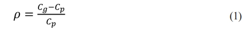
This manuscript aims to explore the lubrication behavior of ceramic bearings with polytetrafluoroethylene (PTFE) cages under low-temperature conditions by studying the friction and contact characteristics between PTFE cages and rolling elements. Taking the 6206CE deep-groove ball bearing as an example, a contact model between rolling elements and cages is established to analyze the mechanical characteristics of the contact between ceramic balls and cages. Friction and wear characteristic tests for the rolling element-cage pairs in full-ceramic ball bearings are carried out, with PTFE as the research subject, to explore the influence of silicon nitride balls with different surface roughness on the friction and wear behavior of PTFE, and to establish the lubrication characteristic laws among components of silicon nitride full-ceramic ball bearings under low-temperature conditions. The research in this manuscript can provide a research foundation for the lubrication characteristics of full-ceramic ball bearings under low-temperature conditions and offer technical support for the application of full-ceramic ball bearings in low-temperature working conditions.
Keywords: Silicon nitride ceramics, Friction and wear, PTFE cage, Low temperature condition
The operation of bearings under low-temperature conditions is primarily influenced by their lubrication characteristics. Conventional lubricants fail to provide reliable lubrication behavior under such conditions [1]. Under extreme conditions, bearings are highly susceptible to transient or short-term oil starvation, leading to dry friction contact between bearing components. This severely affects the performance of bearings in low-temperature applications. Especially in the aerospace field, such as the turbopump of liquid hydrogen/liquid oxygen rocket engines, the working environment temperature is extremely low, and it is necessary to avoid the pollution and volatilization problems caused by traditional grease lubrication, which poses a serious challenge to the oil-free self-lubricating ability of bearings [2]. Therefore, the use of self-lubricating cages for rolling bearings is a key solution to the lubrication behavior of ceramic bearings under low-temperature conditions. The contact and motion relationship between the cage and rolling elements is complex. For example, the contact conditions between ceramic balls and the raceway grooves of the inner and outer rings, as well as between ceramic balls and the cage pocket surfaces, are highly intricate [3, 5]. The lubrication behavior of bearings under low-temperature conditions mainly relies on the self-lubricating effect of the cage material. Thus, establishing a contact model between the cage and ceramic balls is fundamental to analyzing the lubrication effect of self-lubricating cages on full-ceramic ball bearings [6].
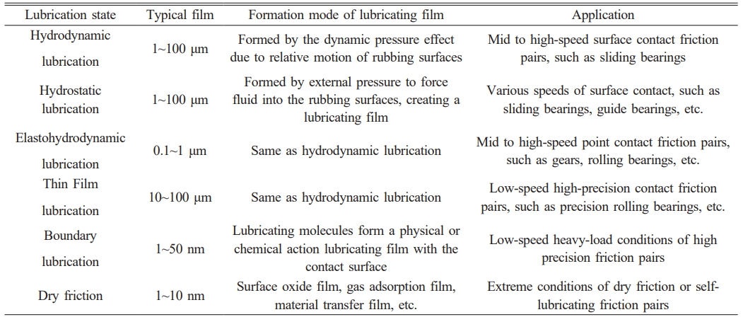
For rolling bearings operating under low-temperature conditions, the main low-temperature media include liquid hydrogen (LH2), liquid oxygen (LO2), liquid nitrogen (LN2), and liquid helium (LHe). The viscosities of these cryogenic fluids are all less than one-fourth of that of water [7, 8]. Therefore, it is difficult to establish an effective hydrodynamic lubrication film between the relatively moving surfaces of the bearings. Under these conditions, the low-temperature fluids can only serve to remove some of the frictional heat, with little impact on the lubrication between bearing components [9, 10]. The purpose of bearing lubrication is to form a lubricating film between two surfaces in relative motion. This film can support normal loads and reduce shear strength in the tangential direction, thereby providing significant lubrication between the friction pairs. Lubrication states can be categorized into six basic types: hydrodynamic lubrication, hydrostatic lubrication, elastohydrodynamic lubrication, thin-film lubrication, boundary lubrication, and dry friction [11, 12]. The formation mechanisms and application scenarios for each lubrication state are shown in Table 1. Under low-temperature conditions, traditional lubricants (oils or greases) solidify and fail, disrupting the friction contact and lubrication medium between bearing components [13]. As a result, the lubrication of bearings is mostly in the form of dry friction, relying on solid lubricating materials to provide lubrication. Due to the limitations of low-temperature media and temperature, bearings cannot use oil or grease lubrication. Therefore, bearings mainly depend on the solid lubricating properties of the cage material to provide lubrication [14-16].
Experimental studies have shown that the friction coefficient of silicon nitride under dry friction conditions is between 0.5 and 0.6 at room temperature, and it exhibits a trend of first increasing and then decreasing with the increase of load [17]. With the continuous development of high-performance new materials, research on polymers and other high-performance solid lubricating materials has gradually been initiated. Introducing solid lubricants into ceramic bearings and utilizing their low friction coefficient to form a continuous solid lubricating layer on the friction surface can endow silicon nitride ceramic bearings with self-lubricating properties [18, 19]. However, the disadvantage of powder solid lubrication is that it is difficult to form a firmly bonded solid lubricating film on the friction surface of silicon nitride ceramic bearings, and solid powder lubricants need to be continuously added. Under dry friction conditions, a variety of polymer materials can form transfer films on the counter-material surface. This is because the material transfer forms an adherent coating on the friction pair surface, which can reduce surface defects on the material to a certain extent, thereby changing the contact state between the friction pairs and providing lubrication [20, 21].
As researchers delve into the tribological properties and applications of polymers, an increasing number of polymers have been proven to possess self-lubricating properties. Generally, metals have high cohesive energy density, while polymers have low cohesive energy density. Therefore, polymers tend to transfer to the surface of metals. If the friction pair consists of the same polymer, a phenomenon occurs where polymers with low cohesive energy density transfer to those with high cohesive energy density [22]. Bahadur et al. have demonstrated that transfer films can form not only between polymers and metals but also between different polymers. This is related to the inherent properties of polymeric materials themselves [23]. During the friction contact process, the surface activation energy of polymeric materials changes with the dynamic characteristics of friction contact and environmental conditions, leading to material detachment, transfer, and reattachment on other material surfaces [23]. Jie Ting et al. conducted wear tests between PTFE three-layer composite materials and bearing steel and found that mechanical action is the main cause of transfer film formation. During relative motion, the micro-asperities on the bearing steel surface will micro-cut the PTFE composite material surface. The chips continuously accumulate between the friction pairs and, under the action of friction heat and compressive force, adhere to the bearing steel surface and expand to form a transfer film. The transfer film undergoes continuous detachment and regeneration during its formation, eventually reaching a dynamic equilibrium [24].
The selection and application of lubricants for bearings under low-temperature conditions is a key issue in solving the operational challenges of bearings in such environments. At present, relevant scholars have conducted research through experimental means, using PTFE as a solid lubricant to perform friction and wear tests on different bearing steel materials. The results show that PTFE, with its self-lubricating properties, can reduce the material friction coefficient under low-temperature conditions and achieve solid lubrication between friction pairs [25, 26]. Currently, extensive research has been carried out on the self-lubricating performance of bearings under low-temperature conditions. PTFE has been used as a cage material to explore the formation mechanism of transfer films during bearing operation and to analyze its self-lubricating properties. Additionally, research has been conducted on the application of ceramic bearings in low-temperature, heavy-load environments. Polymer-based self-lubricating materials, which have good wear resistance, are used in the design and manufacture of cages under low-temperature conditions [27, 28]. Feng W et al. investigated the friction and wear performance of PTFE composites in liquid oxygen/liquid hydrogen, analyzed the working process of PTFE cages, and clarified the effects of factors such as load and rotational speed on the formation, transfer, and rupture of PTFE transfer films [29]. Moreover, low-temperature conditions have a significant impact on the tribological properties of PTFE. The frictional heat generated in the contact zone reduces the cooling capacity of the environment on the material surface. Due to the generation of frictional heat, the wear mechanism of PTFE shifts from abrasive wear under low-temperature conditions to adhesive wear after temperature increase [30].
In summary, the current research on solid lubrication of bearing cage materials mainly focuses on the friction and wear characteristics of PTFE. The wear debris generated during the friction process of polymer materials forms a transfer film on the surface of the rolling elements, which can achieve self-lubrication of the bearings under dry friction conditions. However, research on the solid lubrication characteristics of PTFE and silicon nitride under low-temperature conditions is limited to the material properties themselves. The influence of the surface quality of bearing components on the tribological properties of self-lubricating cages has not been clarified. There is no effective connection established between the manufacturing process and the material's friction and wear characteristics. Furthermore, optimization of the bearing's friction and lubrication properties through control of the surface quality of the friction components has not been achieved.
Cage Contact Model under Low-Temperature Conditions
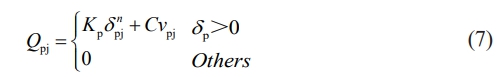
This manuscript focuses on the cage of a compressor bearing for a low-temperature wind tunnel. The bearing in question is a 6206CE deep-groove ball bearing, and the cage pocket shape is cylindrical. During the operation of the bearing, the existence of the cage pocket clearance cp ensures that the cage and rolling elements are constantly in contact, colliding, and rubbing against each other. There are three types of contact relationships between the cage pocket clearance cp and the rolling elements: front-end contact (with the direction of the cage rotation tangent being the front), rear-end contact, and no contact, as shown in Fig. 1. In the actual operation of the bearing, the contact state between the rolling elements and the cage pockets changes constantly and is highly discrete [31].
Based on Fig. 1, the relationship between the pocket clearance cp, the diameter of the rolling element Dw, and the diameter of the pocket Dp can be described as follows:
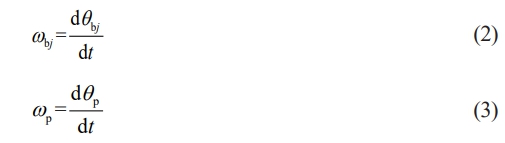
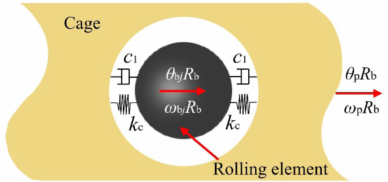
As shown in Fig. 2, by establishing a contact model between the cage pocket and the rolling element, the mutual contact behavior between the cage and the rolling element is simulated. In this model, the contact between the rolling element and the cage pocket surface is simplified to a nonlinear spring-damper model. Additionally, the following assumptions are made for the model: (1) The rolling element and the cage are rigid bodies except in the contact area; (2) The initial position of the model is such that the rolling element and the pocket are concentric. When the model operates at time t, the rotation angle of the j-th rolling element is θbj, and the rotation angle of the cage pocket is θp.
The relationship between the revolution speed ωbj of the j-th rolling element and the rotational speed ωp of the cage is as follows:
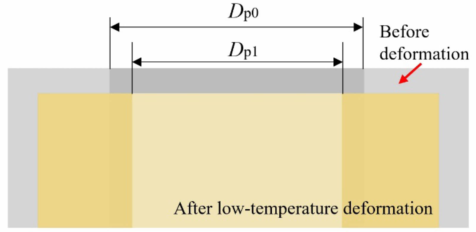
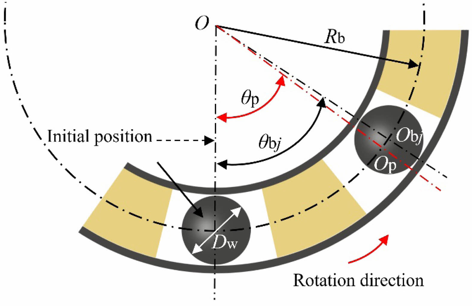
This manuscript discusses the frictional contact state between the PTFE cage and the silicon nitride ceramic balls. Due to the significant difference in the thermal expansion coefficients of the two materials, as the temperature decreases, the pocket clearance cp of the cage will gradually increase, thereby affecting the frictional contact state between the rolling elements and the cage. The schematic diagram of the deformation of the PTFE cage affected by temperature is shown in Fig. 3. Among them, Dp0, Dp1 are the pocket diameters of the cage before and after the temperature decrease, respectively. Considering that the structural dimensions of the pocket clearance change after the cage deforms due to temperature, it is necessary to establish a positional relationship diagram between the rolling elements and the cage pockets to analyze the positional relationship between the rolling elements and the cage pockets, as shown in Fig. 3 and 4.
Let the reference temperature at which the cage material is undeformed be T0, and the temperature under low - temperature operating conditions be T1. Then, the temperature difference for the deformation of the cage is ∆T=T0-T1. The structural deformation δp of the PTFE cage with the change in temperature can be expressed as:

In the formula, αp is the thermal expansion coefficient of the cage material.
Therefore, the diameter of the cage pocket after being deformed due to the influence of low temperature is:

Let δpb be the contact deformation between the rolling element and the pocket. When δpb ≥ 0, it indicates that contact occurs between the rolling element and the surface of the pocket. Combining with the positional relationship between the rolling element and the cage pocket in Fig. 4, the expression for the contact deformation δpb is:
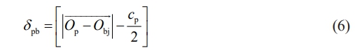
In the formula,  is the position vector change of the center Obj of the ceramic ball in the coordinate system of the cage pocket relative to the center Op of the cage pocket.
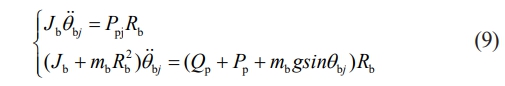
According to the Hertz point contact theory, the nonlinear contact force between the j-th rolling element and the cage pocket is:
In the formula, Kp is the contact stiffness coefficient between the rolling element and the cage pocket; C is the contact damping coefficient; vp is the normal relative velocity at the contact point. From this, it can be known that the friction force between the rolling element and the cage pocket can be expressed as:

In the formula, μp is the friction coefficient between the rolling element and the cage pocket.
Based on the above analysis, differential equations are established for the rolling elements and the cage, respectively.
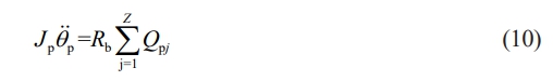
For the rolling elements, this manuscript considers their two degrees of freedom (rotation and revolution), as well as the gravitational force, centrifugal force, and frictional contact force during motion. According to Newton's laws of motion, the system of differential equations for the motion of the j-th rolling element can be obtained as
In the formula, mb represents the mass of the rolling element; Jb represents the moment of inertia of the rolling element; g represents the acceleration due to gravity.
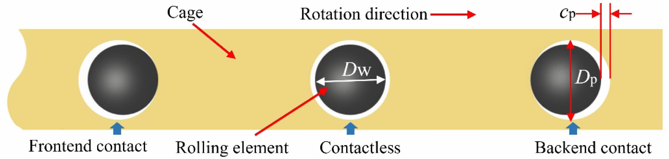
For the cage, during the analysis, only the degree of freedom of its rotation around the bearing axis is considered, and only the forces resulting from the frictional contact and collision between the rolling elements and the pocket surfaces are taken into account. The resulting differential equation is:
In the equation, Jp represents the moment of inertia of the cage.
By solving the aforementioned system of motion differential equations using the fourth-order Runge-Kutta method, the forces and motion characteristics of the rolling elements and the cage can be obtained, thereby analyzing the contact characteristics between the rolling elements and the cage.
Analysis of Contact Forces between Rolling Elements and Cage under Different Temperature Conditions
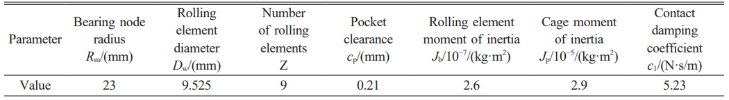
This manuscript takes the 6206CE bearing as the research subject, and its main structural parameters are shown in Table 2. The aforementioned dynamic model is used to analyze the contact forces between the rolling elements and the cage.
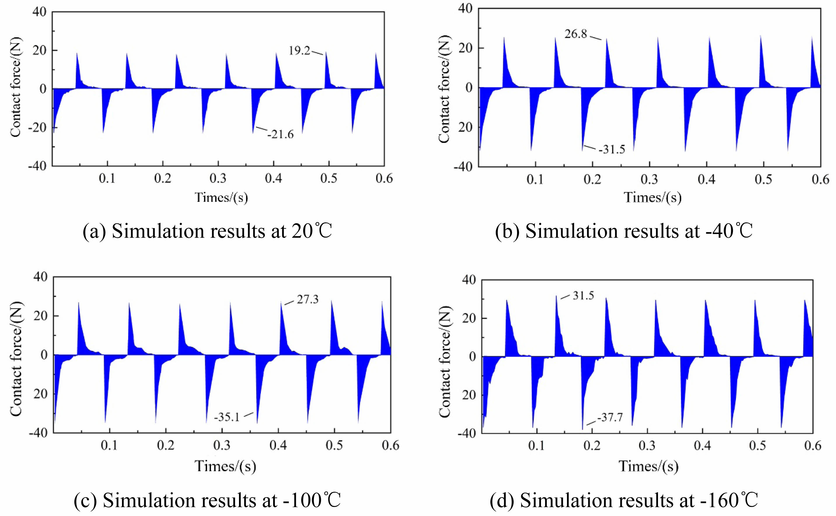
Calculations and analyses were conducted within the range of working conditions with a load of 1 kN, a frictional linear velocity of 0.36 m/s, and temperatures of 20 ℃, -40 ℃, -100 ℃, and -160 ℃. The variation of contact forces between the rolling elements and the cage over time is shown in Fig. 5. As can be seen from the figure, a positive contact force indicates that the rolling element is in contact with the front end of the cage pocket, while a negative value indicates contact with the rear end. The rolling elements experience intermittent collisions with the front and rear ends of the cage pockets, and the amplitude of contact forces varies with each collision, indicating a certain degree of uncertainty in the contact between the rolling elements and the cage pockets [32]. Furthermore, the computational results show that the actual contact force between the rolling elements and the cage is much less than the load applied to the bearing. As the temperature decreases, the contact force between the rolling elements and the pocket surfaces of the cage gradually increases. When the temperature reaches -160 ℃, the maximum contact force reaches -37.7 N. The reason for this result is that as the test environment temperature decreases, PTFE exhibits increased hardness. When the rolling elements come into contact with pocket surfaces of different hardness levels, the harder pocket surfaces will reflect a greater contact force. The above results will provide parameter basis for the subsequent experiments on the friction and wear performance and lubrication characteristics of PTFE cage materials and silicon nitride balls.
|
Fig. 1 The contact state between cage and rolling element. |
|
Fig. 2 Contact model between rolling element and cage. |
|
Fig. 3 Cage deformation diagram. |
|
Fig. 4 Position relation between rolling body and cage pocket hole. |
|
Fig. 5 Change of contact force between roller and cage with time. |
Test Materials
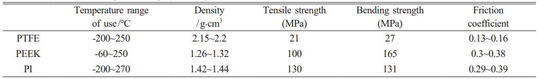
At present, the selection of cage materials for full-ceramic ball bearings is mainly concentrated in the field of engineering plastics, including polytetrafluoroethylene (PTFE), polyetheretherketone (PEEK), and polyimide (PI). The performance comparisons of the three types of cage materials are shown in Table 3.
As shown in Table 3, PTFE exhibits several key advantages as a bearing cage material, including its low friction coefficient and wide service temperature range. Compared to polyimide (PI), although their temperature capabilities are similar, PTFE offers a significant cost advantage, making it widely adopted in bearing applications. PTFE's properties, such as low-temperature resistance, anti-aging performance, low friction coefficient, and self-lubricating behavior, are critical for maintaining bearing efficiency under extreme conditions. Under low-temperature environments, the friction and wear characteristics of PTFE directly determine the operational performance of the cage and serve as a vital reference for evaluating the reliability of full-ceramic ball bearings in cryogenic applications.
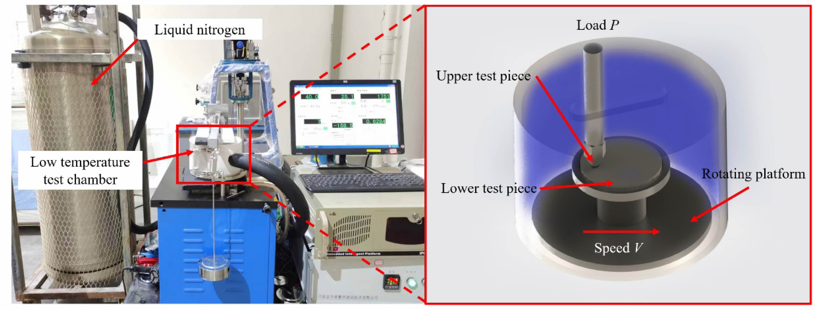
Experimental Equipment and Scheme
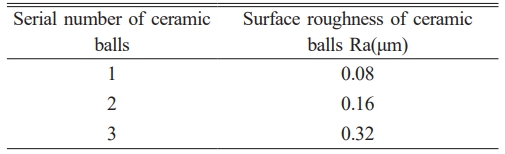
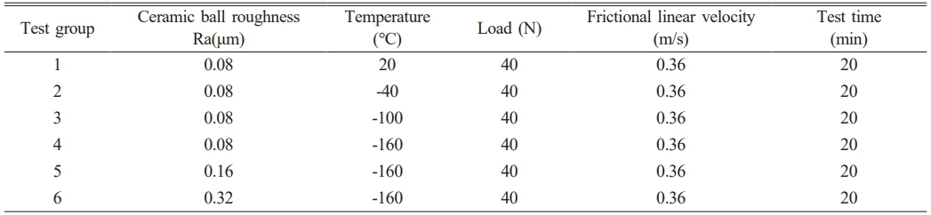
The experiments were conducted on a low-temperature friction and wear tester provided by Jinan Yihua Tribology Test Technology Co., Ltd. The tester offers a temperature range of -160 to 20 ℃ with a temperature control accuracy of ±2 ℃, an axial load range of 10~500 N, and a spindle speed range of 5~2000 r/min (with an error of ±1 r/min below 100 r/min and ±5 r/min above 100 r/min). The apparatus is illustrated in Fig. 6.The tests were performed within a cryogenic chamber. The upper specimen (a ceramic ball) was fixed by a chuck, while the lower specimen (a PTFE disk) was mounted on a rotating platform driven by a motor to achieve ball-on-disk rotational motion. Liquid nitrogen was used to cool and maintain the temperature of the test chamber. The test piece combination adopts a Si3N4-PTFE ball-disc pairing, in which the silicon nitride ceramic ball has a size of φ6.35 mm, and the PTFE disc has a size of φ50 mm and a thickness of 5 mm. Due to the significantly lower hardness and compressive strength of PTFE compared to silicon nitride, all elastic-plastic deformations during the test occurred in the PTFE material. Thus, the influence of PTFE surface roughness on the friction coefficient was negligible, and only the effect of ceramic ball surface roughness on the tribological performance of PTFE was investigated. The surface roughness parameters of the ceramic balls are listed in Table 4, and the experimental design is presented in Table 5. To ensure the reliability of the experimental data, three repetitive experiments were conducted under the same conditions in all the experiments in this manuscript, and the results of the three experiments were analyzed.
|
Fig. 6 Structure and working principle of low temperature friction and wear testing machine. |
Effect of Temperature on Friction Coefficient of PTFE
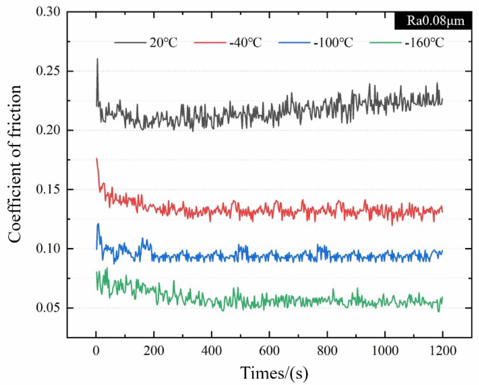
Figure 7 shows the variation law of friction coefficient between silicon nitride with surface roughness Ra 0.08 μm and PTFE under different temperature environments. It can be seen from the figure that the friction coefficient decreases with the decrease of temperature during the test. Under the condition of 20 ℃, the friction coefficient generally shows a gradually increasing trend, reaching the minimum value of about 0.2 near 180s. With the continuation of the test process, near 1200s, the friction coefficient gradually increases to about 0.23. When the test temperature condition is reduced from 20 ℃ to -40 ℃, the friction coefficient is reduced to about 0.13, with a reduction of about 43.5%. And under this temperature condition, with the increase of test time, the friction coefficient generally shows a relatively stable change law. When the test temperature is reduced from -40 ℃ to -100 ℃, the friction coefficient is reduced to about 0.09, with a reduction of about 30.8%. When the test temperature is reduced from -100 ℃ to -160 ℃, the friction coefficient is reduced to about 0.06, with a reduction of about 33.3%. At the same time, the overall variation law of the friction coefficient under the conditions of -100 ℃ and -160 ℃ is similar to that of the friction coefficient at -40 ℃.
The main reasons for the decrease in the friction coefficient of Si3N4-PTFE under low-temperature conditions can be analyzed as follows. First, the increase in the hardness of PTFE material itself under low-temperature conditions leads to a reduction in material deformation under load. When the test load remains constant, the effective contact area between the friction pairs decreases due to the increase in material hardness, ultimately resulting in a decrease in the material's friction coefficient. Additionally, during the test, due to the presence of the liquid cryogenic medium (LN2), the liquid cryogenic medium easily forms a liquid film between the friction pairs. The formation of this film helps to prevent direct contact between the friction pairs and plays a lubricating role to a certain extent
Effect of Temperature on Wear Rate of PTFE
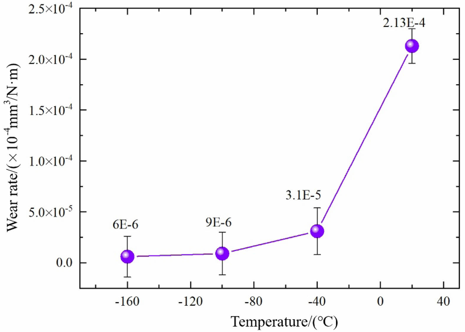
The wear rate reflects the efficiency of material surface damage and removal during the friction and wear process, serving as an important index for evaluating the wear resistance of friction-contact moving pair components. As shown in Fig. 8, it presents the variation of wear rate for the Si3N4-PTFE pair based on the calculation results of Eq. (11). From Fig. 8, the variation trend of the wear rate is similar to the friction coefficient trend under the same temperature conditions. At 20 ℃, the wear rate is approximately 2.13×10⁻⁴mm3/N·m. When the test temperature is below 20 ℃, the wear rate of the material decreases with decreasing temperature. When the temperature reaches -160 ℃, the wear rate reaches a minimum of about 6.0×10⁻⁶ mm3/N·m. Analysis shows that the increase in PTFE hardness under low-temperature conditions contributes to the improvement of material wear resistance, indicating that PTFE is suitable for low-temperature applications. Additionally, although the wear resistance of PTFE is significantly enhanced at low temperatures, there is still an order-of-magnitude gap compared to silicon nitride. Therefore, during friction contact, wear debris primarily originates from the PTFE material

In the formula, Δm (mg) is the mass loss of the material, ρ(mg/mm³) is the density of the material, F (N) is the applied load, and L (m) is the total sliding distance.
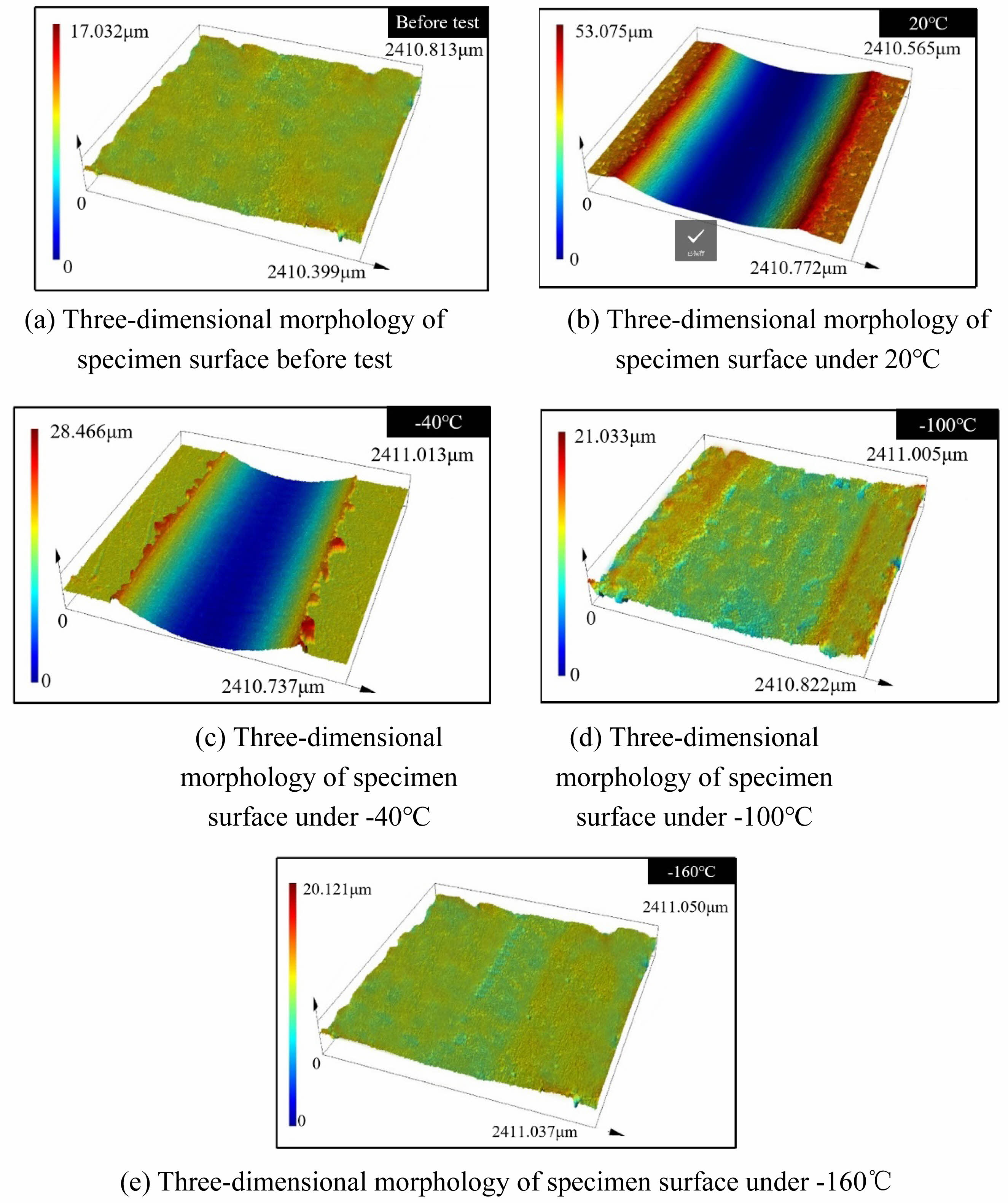
Figure 9 shows the wear profiles of the PTFE surface before and after the test. Fig. 9(a) presents the three-dimensional morphology of the PTFE surface before the test, while Figs. 9(b) to 9(e) show the three-dimensional morphologies of the PTFE surface after Tests 1 to 4 according to the experimental scheme in Table 5. The results indicate that the surface morphology of PTFE is significantly affected by temperature changes after the friction and wear test.
As shown in Fig. 9(b), the silicon nitride ball leaves obvious wear marks on the PTFE surface under the 20 ℃ condition, with a large wear width and depth. The surface of the wear groove is smoother than the unworn surface. Due to the lower hardness of the PTFE material at this temperature, significant material extrusion and accumulation occur on both sides of the wear groove.
As shown in Fig. 9(c), due to the increase in material hardness caused by the decrease in temperature, the depth and width of the surface grooves after the test under the -40 ℃ condition are significantly smaller than those of the 20 ℃ test results. The groove surface is relatively smooth, and the extruded and accumulated materials on both sides of the groove are reduced compared to the 20 ℃ condition. The above changes are caused by the increase in hardness of the material due to the influence of the low-temperature environment, which ultimately leads to a decrease in the amount of material deformation during the test.
As shown in Fig. 9(d), when the test temperature is -100 ℃, the width and depth of the wear grooves are significantly smaller than the results of the previous two groups of tests. The amount of extrusion deformation of the PTFE surface by the silicon nitride balls can be observed, but the width and depth of the grooves are much smaller than those of the previous two groups of tests, and no material extrusion and accumulation occurs on both sides of the grooves.
As shown in Fig. 9(e), when the test environment temperature is -160 ℃, the wear depth and width of the PTFE surface are significantly reduced again, and the surface after wear is close to the initial untested surface. This result proves that when the temperature reaches -160 ℃, the hardness and wear resistance of the PTFE material are superior to those at 20 ℃. It can be seen that under low-temperature conditions, PTFE has the advantages in friction and wear performance as a bearing cage and other components during application.
Effect of Ceramic Ball Surface Roughness on Friction Coefficient of PTFE
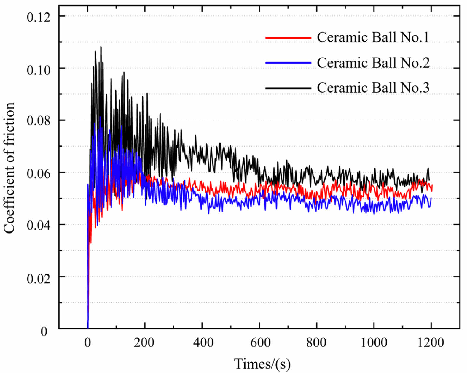
Figure 10 shows a comparison of friction coefficients between silicon nitride ceramic balls with different surface roughness and PTFE pairs. It can be seen from the figure that under the same test conditions, changing the surface roughness of ceramic balls can significantly alter the friction coefficient between friction pairs. When the test uses ceramic balls with a surface roughness of Ra 0.08 μm, the friction coefficient generally shows a stable change trend during the test, with the average friction coefficient stabilizing at approximately 0.052. When ceramic balls with a surface roughness of Ra 0.16 μm are used, the friction coefficient exhibits a large fluctuation range in the first 200 seconds of the test. As the test progresses, the friction coefficient gradually decreases to about 0.047, and the fluctuation range of the friction coefficient significantly narrows. When the test is conducted with ceramic balls having a surface roughness of Ra 0.32 μm, the fluctuation range of the friction coefficient further expands in the early stage of the test, and as the test progresses, the friction coefficient stabilizes at approximately 0.06. In addition, the time for the fluctuation range of the friction coefficient to narrow in the test group of ceramic balls with a surface roughness of Ra 0.32 μm is significantly longer than that in the test group of ceramic balls with Ra 0.16 μm.
The change in surface roughness of silicon nitride can affect the friction and wear behavior of the pair with PTFE. Analysis shows that the influence of surface roughness of silicon nitride ceramic balls on the friction coefficient of PTFE presents a non-linear variation law. The friction coefficient achieved by the test results of ceramic balls with a surface roughness of Ra 0.08 μm is not the optimal result among the three groups of tests. The optimal test result mentioned above is the pair of ceramic balls with a surface roughness of Ra 0.16 μm and PTFE.
Combined with the analysis of the phenomenon of large fluctuations in the friction coefficient in the early stage of the test, it can be seen that with the progress of the test, the decrease in the friction coefficient may be due to the formation of a transfer film by PTFE wear debris during the friction and wear process, which improves the lubrication performance between the friction pairs. The friction coefficient of the friction pair of ceramic balls with a surface roughness of Ra 0.32 μm fluctuates greatly in the early stage, and the running-in time is also much longer than that of ceramic balls with Ra 0.16 μm. It can be concluded from the above analysis that when processing the surface roughness of ceramic bearing components, a lower surface roughness value is not necessarily more conducive to the frictional contact between components.
Formation Mechanism and Lubrication Characteristics Analysis of PTFE Self-lubricating Transfer Film
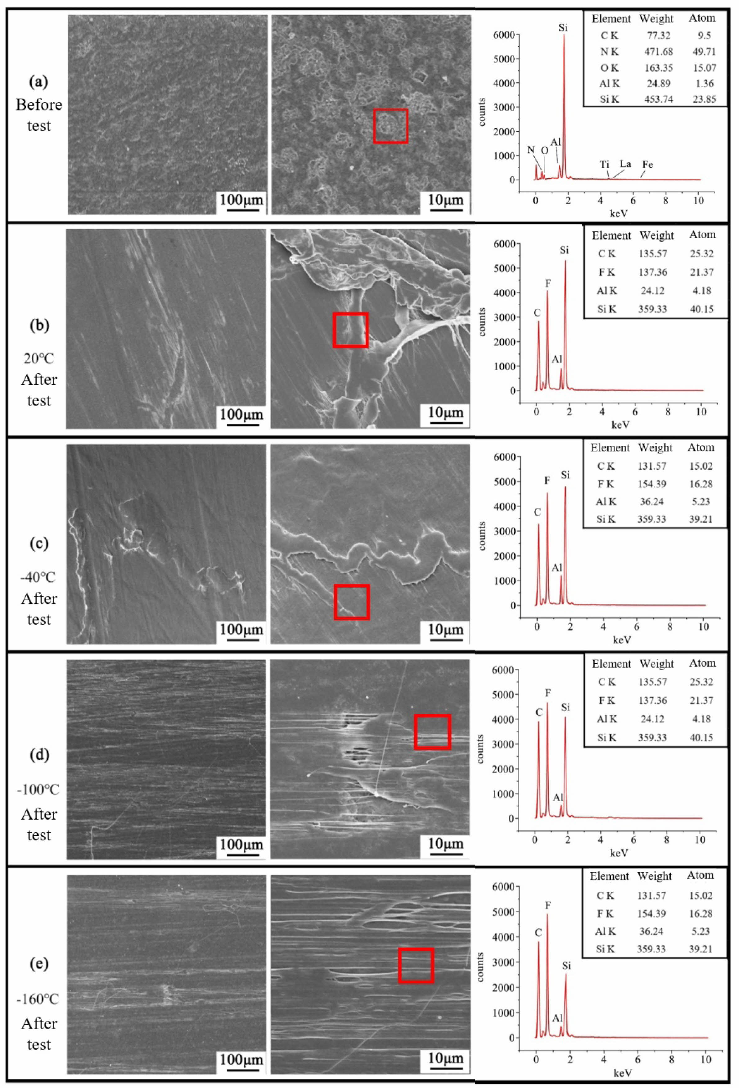
Figure 11 shows the surface morphology and elemental analysis of a silicon nitride ball with a surface roughness of Ra 0.16 μm after the friction and wear test under low-temperature conditions for the silicon nitride-PTFE pair. Fig. 11(a) presents the surface morphology of the silicon nitride ball before the test. Elemental analysis indicates that only the main constituent elements of silicon nitride (Si, N, Al) and trace elements (Fe, La, Ti) from sintering aids are detected on the surface before the test.
Figure 11(b) shows the surface morphology of the friction contact area of the silicon nitride ball after the test at 20 °C, where a large amount of PTFE wear debris is aggregated in the contact zone. Based on previous analyses, the silicon nitride surface undergoes almost no wear in the silicon nitride-PTFE friction pair, so all wear debris during the test originates from the PTFE surface. A film-like substance is clearly observed enveloping the silicon nitride surface. Elemental analysis reveals that the surface region is primarily composed of C, F, Si, and Al—i.e., the main elements of both silicon nitride and PTFE—with relatively high contents of C and F. This confirms that PTFE wear debris adheres to the silicon nitride ball surface after the friction and wear test under these conditions.
Figure 11(c) shows the surface morphology of the silicon nitride ball after the test under the -40 °C condition. Compared with the silicon nitride ball surface at 20 °C, the coverage area of the PTFE film is relatively reduced. It can be inferred that the transfer film formed by PTFE on the silicon nitride surface is more uniform at this temperature than that at 20 °C. Elemental analysis of the silicon nitride ball surface under this condition shows that the main constituent elements remain C, F, Si, etc., but the relative content of the Si element changes significantly—the content of the Si element increases relatively, indicating that the content of the PTFE film is relatively reduced at this temperature.
Figures 11(d) and 11(e) present the surface morphologies of the silicon nitride ball after tests under -100 °C and -160 °C conditions. As shown, with the further decrease of the test temperature, the PTFE transfer film still forms on the silicon nitride surface, but its morphology differs from that under 20 °C and -40 °C. The lower the temperature, the more uniform the transfer film becomes. Elemental analysis reveals that as the friction test temperature decreases, the relative contents of F and C elements are both lower than that of Si. This indicates that with the decrease in ambient temperature, the PTFE transfer film in the form of large agglomerates gradually disappears, and the content of filamentous transfer film relatively increases.
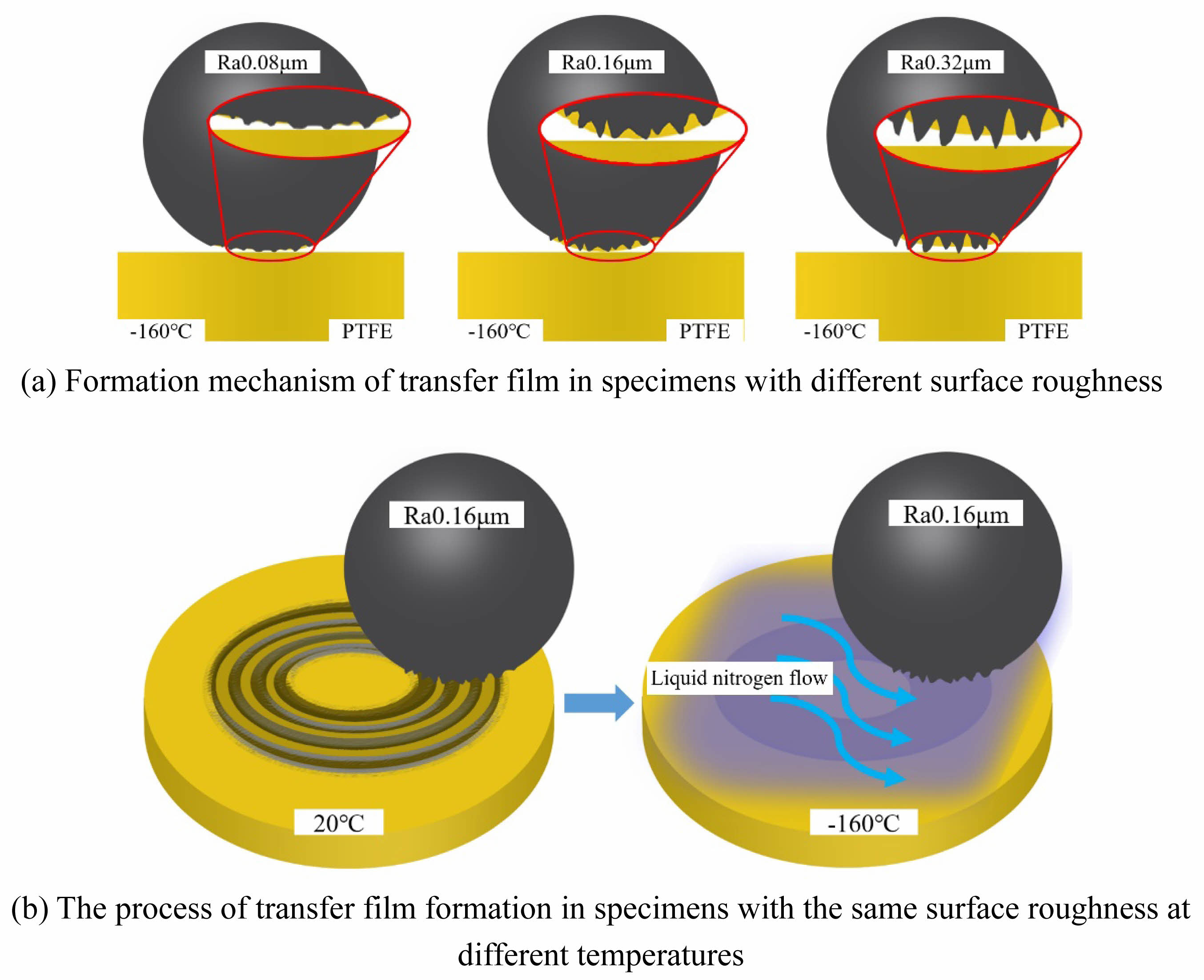
Figure 12 illustrates the mechanism of PTFE transfer film formation during the testing process. Fig. 12(a) shows the mechanism of PTFE transfer film formation when silicon nitride balls with different surface roughnesses are in friction and wear contact with a PTFE surface under the condition of -160 °C. From this figure, it can be seen that when the surface roughness is Ra 0.08 μm, due to the lower surface roughness value of the specimen, the wear removal capability of the silicon nitride surface asperities on PTFE during the frictional contact process is relatively low. Therefore, only a small amount of PTFE grinding is attached to the surface of silicon nitride with this roughness, and a large and uniform PTFE transfer film is not formed. When the surface roughness is Ra0.16 μm, due to the increase in the volume and number of silicon nitride ball surface asperities, the frictional removal capability on the PTFE surface is relatively enhanced during the frictional contact process. Hence, a relatively uniform PTFE transfer film can be attached to the surface of silicon nitride balls with this roughness. When the surface roughness reaches Ra0.32 μm, due to the excessive volume of the silicon nitride ball surface asperities, the wear debris formed by the wear removal of the PTFE surface cannot effectively compensate for the defects of the silicon nitride surface asperities. Therefore, during the friction and wear test on this surface, its coefficient of friction is actually increased.
As shown in Fig. 12(b), the process of transfer film formation during the friction and wear test of silicon nitride balls with a surface roughness of Ra 0.16 μm against PTFE under different temperature conditions is depicted. At 20 °C, due to the action of frictional heat, PTFE softens and undergoes elastoplastic deformation, leading to an increase in contact area with the surface of the silicon nitride ball. During sliding friction, a large amount of PTFE wear debris is easily produced, which adheres to the surface of the silicon nitride ball, forming a relatively thick transfer film. Under this temperature condition, the sliding contact interface is uneven, and the friction between PTFE and the silicon nitride ball gradually transforms into friction between PTFE and the transfer film. During the process where PTFE is subjected to shear force, on one hand, new wear debris is generated, and on the other hand, liquid nitrogen carries away some of the wear debris produced by the transfer film, thus the transfer film is in a dynamic process of continuous shedding and re-adhesion. When the test temperature is reduced to -160 °C, the hardness of the PTFE matrix increases, the amount of wear debris generated decreases, the deformation of the material is reduced, the sliding contact interface with the silicon nitride ball is relatively flat, the contact area is decreased, and the shear force acting on the material is reduced. Therefore, the transfer film formed is thin and evenly distributed over the contact interface, providing good lubrication.
|
Fig. 7 Comparison of friction coefficients of Si3N4-PTFE under different temperature conditions. |
|
Fig. 8 Average wear rate of Si3N4-PTFE under different temperature conditions. |
|
Fig. 9 Three-dimensional morphology of PTFE wear surface under different temperature conditions. |
|
Fig. 10 Influence of ceramic ball with different surface roughness on friction coefficient. |
|
Fig. 11 Surface transfer films of Si3N4 spheres at different temperature conditions. |
|
Fig. 12 Formation mechanism of PTFE transfer film. |
This manuscript conducts experimental research on the friction and wear performance of Si3N4-PTFE pairs, deeply analyzes the influence of temperature and ceramic ball surface roughness on friction and wear performance, and analyzes the formation and characteristics of PTFE material transfer films. The specific research conclusions are as follows:
(1) Under low-temperature conditions, the friction coefficient of PTFE decreases with the decrease of test temperature. When the test temperature reaches -160 °C, the friction coefficient decreases to about 0.06. The reasons for the decrease in the friction coefficient of PTFE under low-temperature conditions include: the decrease in temperature leads to an increase in the hardness of the material itself, which in turn reduces the contact area of the friction pair, and finally leads to a decrease in the friction coefficient. At the same time, the liquid nitrogen medium easily forms a liquid film between the friction pairs, which helps to lubricate.
(2) Under low-temperature conditions, with the decrease of the test environment temperature, the change rate of the material friction coefficient gradually decreases. The change rate of the friction coefficient from 20 °C to -40 °C is much higher than that from -40 °C to -160 °C. The reason for this result is that the PTFE material itself has a special spiral chain structure, which is significantly affected by changes in the environment temperature. When the material temperature is lower than 19 °C, the microscopic spiral chain structure of the PTFE material is arranged closely, so macroscopically, it is manifested as an increase in the hardness and strength of the material, further verifying that PTFE has self-lubricating properties under low-temperature conditions.
(3) Under low-temperature conditions, the wear rate of PTFE decreases with the decrease of temperature. When the temperature reaches -160 °C, the wear rate reaches a minimum of approximately 6.0×10⁻⁶ mm3/N·m. As the test temperature decreases, the width and depth of wear marks on the PTFE surface gradually decrease, and the lower the test environment temperature, the lower the surface roughness of the wear grooves. This conclusion is consistent with the conclusion that the friction coefficient decreases with the decrease of temperature.
(4) The surface roughness of silicon nitride ceramic balls has a certain influence on the test friction coefficient. When friction and wear tests are conducted between ceramic balls with surface roughness of Ra 0.08 μm, Ra 0.16 μm, and Ra 0.32 μm and PTFE, the friction coefficient of the pair with ceramic balls of Ra 0.16 μm roughness is the lowest.
The authors would like to acknowledge the support of the Liaoning Provincial Science and Technology Plan Joint Plan (Natural Science Foundation-PhD Research Startup Project) [grant number 2024-BSLH-238], the Open Project of "Key Laboratory of High end Ceramic Bearings" at Shenyang Jianzhu University in 2024 [grant number SJUKLHCB05].
- 1. Y. Wu, R. Chen, D. Qian, and W. Wei, Mater. Prot. 53[6] (2020) 1-5+11.
- 2. J. Xu, Q. Jia, F. Zhang, X. Yuan, and C. Zhang, Proc. Inst. Mech. Eng. Part J-J. Eng. Tribol. 232[5] (2018) 582-591.
- 3. J. Sun, Z. Zhang, Z. Xia, X. Fang, R. Guan, G. Zhang, and J. Yao, J. Ceram. Process. Res. 24[3] (2023) 541-553.
-

- 4. J. Sun, J. Huang, Z. Tian, Z. Xia, L. Wang, and Y. Zhang, J. Ceram. Process. Res. 25[6] (2024) 975-984.
-
- 5. D. Lee, B. Jang, B. Kim, and K. Lee, J. Ceram. Process. Res. 20[5] (2019) 499-504.
-
- 6. Y. Li, W. Li, Y. Zhu, G. He, S. Ma, and J. Hong, Lubricants 10[7] (2022) 149.
-
- 7. A. Pramono, M. Nura, J. Soedarsono, and N. Indayaningsih, J. Ceram. Process. Res. 20[1] (2019) 1-7.
-
- 8. G. Zhang and X. Yan, Ind. Lubr. Tribol. 66[1] (2014) 31-37.
- 9. R. Surendrana and A. Kumaravelb, J. Ceram. Process. Res. 24[5] (2023) 899-906.
-
- 10. Y. Wang, S. Li, C. Wei, Y. Zhang, G. Lin, D. An, and J. Zhao, J. Ceram. Process. Res. 25[4] (2024) 643-659.
-
- 11. S. Wen, and P. Huang, in “Principles of Tribology (Second Edition)”(Beijing: Tsinghua University Press, 2002) p. 85.
-
- 12. S. Li, J. Zhao, Y. Wang, G. Lin, C. Wei, Z. Xia, C. Jia, and T. Jing, J. Ceram. Process. Res. 26[3] (2025) 472-482.
-
- 13. Q. Wang, S. Sun, S. Li, and Z. Guo, Ceram. Int. 44[18] (2018) 22680-22685.
-
- 14. F. Ning, in (Beijing: Chemical Industry Press, 2021), pp. 37-50.
- 15. J. Shi and L. Wang, J. Mech. Eng. 52[3] (2016) 86-92.
- 16. S. Ahn and K. Nam, J. Ceram. Process. Res. 17[10] (2016) 1046-1051.
-
- 17. H. Nam and K. Nam, J. Ceram. Process. Res. 22[1] (2021) 66-73.
-
- 18. P. Wang, S. Li, Y. Wu, and J. Zhao, J. Ceram. Process. Res. 25[4] (2024) 694-703.
-
- 19. B. Li and Z. Cao, Surf. Technol. 46[9] (2017) 32-38.
- 20. E. Feyzullahoglu and Z. Saffak, Mater. Des. 29[1] (2008) 205-211.
-
- 21. S. Feng, S. Kondo, T. Kaseyama, T. Nakazawa, T. Kikuchi, R. Selyanchyn, S. Fujikawa, L. Christiani, K. Sasaki, and M. Nishihara, J. Membr. Sci. 548 (2018) 223-231.
-
- 22. M. Kyeong, J. Chae, S. Lee, T. Lim, M. Kim, S. Lee, K. Song, and H. Kim, J. Membr. Sci. 660 (2022) 120853.
-
- 23. S. Bahadur, Wear 245[1-2] (2000) 92-99.
-
- 24. S. Shi, J. Wu, and Y. Peng, Wear 408 (2018) 208-213.
-
- 25. X. Yin, J. Tu, W. Qin, S. Han, and K. Gu, Mater. Prot. 51[10] (2018) 27-30+100.
- 26. J. Wu, J. Zhu, L. Mu, Y. Shi, Y. Dong, X. Feng, and X. Lu, Tribol. Int. 94 (2016) 315-322.
-
- 27. Z. Hu, M. Shao, J. Guo, S. Huang, and X. Xu, Opt. Precis. Eng. 25[5] (2017) 1250-1258.
-
- 28. A. Kumar, S. Ghosh, and S. Aravindan, Ceram. Int. 45[14] (2019) 17447-17466.
-
- 29. W. Feng, L. Yin, Y. Han, J. Wang, K. Xiao, and J. Li, Ind. Lubr. Tribol. 73[1] (2021) 82-87.
-
- 30. E.N. Brown, P.J. Rae, and E.B. Orler, Polymer 47 (2006) 7506-7518.
-
- 31. Y. Luo, B. Yang, and W. Tu, J. Aeronaut. Power 37[12] (2022) 2887-2895.
- 32. Y. Wang, W. Wang, T. Qing, and S. Zhang, J. Mech. Eng. 54[9] (2018) 9-16.
- 33. Z. Wang, S. Li, J. Sun, Y. Sui, C. Ma, and X. Zhang, Lubr. Sealing 47[9] (2022) 86-91.
 This Article
-
2025; 26(5): 754-766
Published on Oct 31, 2025
- 10.36410/jcpr.2025.26.5.754
- Received on Jul 10, 2025
- Revised on Aug 27, 2025
- Accepted on Sep 8, 2025
Services
- Abstract
introduction
analysis of cage contact characteristics under low-temperature conditions
experimental study on friction and wear between ptfe cage material and silicon nitride under low-temperature conditions
results and discussion
conclusions
- Acknowledgements
- References
- Full Text PDF
Shared
Correspondence to
- Yonghua Wang
-
aShenyang Jianzhu University, Key Laboratory of High-end Ceramic Bearing, Shenyang 110168, China
c Shenyang Jianzhu University, School of Mechanical Engineering, Shenyang 110168, China
Tel : 18624057650 Fax: 024-24692192 - E-mail: yonghua0514@sjzu.edu.cn
Clean-Energy Research Institute(CRI), Hanyang University, 222, Wangsimni-ro, Seongdong-gu, Seoul, 04763, Korea
E-mail: jcpr@hanyang.ac.kr