


- Design, modelling and verification of a fully decoupled large-stroke compliant motion stage
Xinyu Liu*
Department of Mechanical Engineering, University College London, London, WC1E 6BT, The United Kingdom
This article is an open access article distributed under the terms of the Creative Commons Attribution Non-Commercial License (http://creativecommons.org/licenses/by-nc/4.0) which permits unrestricted non-commercial use, distribution, and reproduction in any medium, provided the original work is properly cited.
The increasing demand for large-stroke positioning systems with high-precision in applications such as semiconductor manufacturing, optical alignment, and biomedical devices has greatly motivated the development of the large-stroke compliant motion stage. This paper proposes a novel design that employs a symmetrical double parallelogram flexure module (DPFM) to achieve motion decoupling and subsequently minimize parasitic errors. Aluminium 7075-T6 is chosen for its high strength-to-weight ratio, fatigue resistance, and machinability, enabling the compliant motion stage to withstand both dynamic and static loads without compromising performance. Finite element analysis (FEA) results reveals that the design closely matches theoretical model, with an average percentage motion error of 0.956% relative to theoretical calculation. The compliant motion stage achieves a maximum actuation range of ±5 mm on both X and Y direction within elastic-regime of the material, while the averaged parasitic motion detected is 0.148% of the desired motion, which validates its fully decoupled motion. Modal analysis shows that the theoretical natural frequencies of the first two modes are 17.375 Hz, corresponding to motion along the X and Y axes. Compared to the FEA modal simulation result, the mathematical model produces 2.524% and 3.144% difference for the first and second mode respectively, which verifies the symmetric design and dynamic stability. Furthermore, the optimized length-to-thickness ratio provides robust buckling resistance, ensuring reliability under compressive loads. Preliminary fatigue stability is also demonstrated through finite element simulations over 50 loading cycles, showing no observable degradation within the elastic regime.
Keywords: Compliant mechanism, Finite Element Analysis (FEA), Structural design, Large-stroke.
Precision compliant motion stages are a critical area of research and development in disciplines that necessitate highly precise positioning, including semiconductor packing, optical systems, and micro-positioning systems [1-3]. Compliant motion stage that are intended to translate or rotate with submillimetre precision, have evolved in response to the necessity for miniaturized components with precise motion control. The compliant mechanism approach is employed to accomplish accuracy, compactness, and reliability. For instance, in the microscopy system, the individual collagen fibrils are separated by interfibrillar spaces measuring between 10 and 20 µm, which necessitates exceptional precision for accurate characterisation and manipulation at this micro-scale [4]. In order to reach large travel range, i.e. ± 5 mm in this paper, electromagnetic actuators [5], specifically voice coil motors (VCMs) [6] are commonly employed for precise actuate. Moreover, these motors are also applicable for some extreme applications of compliant motion stage that require dust-free or vacuum working conditions, in order to be utilized in professional areas.
High-precision compliant motion stage must exhibit a large motion range along the X and Y axes while maintaining small parasitic motion between these axes. They also require actuator isolation for large-stroke, single-axis actuation and minimization of parasitic errors along non-actuated directions. Various existing designs for compliant motion stage have been proposed, Chen et al. introduced a compliant parallel X-Y-Z micro-motion stage based on flexure hinges and driven by piezoelectric actuators. Their design achieved fully decoupled motion, addressing parasitic errors effectively [7].Similarly, Wang et al. proposed a novel flexure-based X-Y micro positioning stage designed to improve positioning accuracy and motion performance. It highlights the advantages of flexure mechanisms in achieving precision and decoupled motion [8]. Building upon these prior studies, the intended structural design of the compliant motion stage in this paper focuses on achieving decoupling the motion of the two axes independent movement along the X and Y axes, which is critical for minimizing parasitic errors and ensuring precise motion. This will eradicate cross-axis interference, thereby enhancing the quality of motion across a wide displacement range. Ceramic structural integrity and residual stress behaviour have been systematically reviewed in the literature, providing context for stiffness uncertainty in manufactured components.
In order to achieve this objective, symmetric double parallelogram flexure module (DPFM) is employed at the compliant motion stage as its primary structural component. This is down to the reason that the DPFM design guarantees precise linear motion in all directions while simultaneously preserving stability and equilibrium [9]. Consequently, the employment of this symmetric module will not only improve the stage's reliability but also enhances its accuracy, which is suitable for high-precision applications that require minimal parasitic errors and decoupled motion.
The motivation for this research lies in the need to achieve large-range motion for both X and Y direction with decoupled motion. A well-decoupled compliant motion stage generally means that each motor generates motion in only one specific direction without influencing movements along other axes, and the term ‘decoupled’ refers to the independent output motion of the compliant motion stage, which ensures that movement in one axis does not interfere with the others.
Finite Element Analysis (FEA) is used to evaluate the proposed designs, with the goal of creating an improved compliant mechanism with effective constraints. The design of high-performance compliant mechanisms is inspired by the structural principles of rigid parallel mechanisms, while benefiting from the unique advantages of flexibility for achieving fine precision and simplicity. The integration of compliant joints and optimized structural layouts enables the attainment of both static and dynamic performance capabilities as well as an extended travel range. The major challenge lies in the fact that high-performance designs with substantial travel ranges lack practical instances for robust parametric optimization related to versatile applications. The solution is to introduce a systematic approach through the combination of innovative structural design, and a comprehensive static and dynamic analysis. It moves towards the development of a compliant motion stage moving ±5 mm in both X and Y directions, essentially allowing accuracy, reliability, and compactness for an efficient design. Thus, its flexibility makes it a valuable platform for use in various high-precision positioning systems, especially where compact design is critical and precise control is demanded.
This paper focuses on the compliant motion stage employed with DPFM, the structural design and mathematical modeling of the compliant motion stage are proposed, including the stiffness model and critical load analysis. Then, Finite Element Analysis (FEA) is conducted to verify motion accuracy, stress distribution, and dynamic characteristics. Based on the simulation results, the relationship between stiffness and parasitic motion is analysed, and the effectiveness of the symmetric double parallelogram flexure module (DPFM) is discussed.
In this section, DPFM is used as the key idea for the structural design. Based on this concept, the design of compliant motion stage is proposed with mathematical models for calculation. Then, the mathematical models are compared with FEA result with the use of Ansys ADPL solver.
Stiffness model of the stage
To effectively analyse the mechanical response of the structure under applied forces, a normalized formulation is initially utilized. This approach simplifies the governing equations, making them scalable and applicable to a wide range of beam configurations. For example, the normalized displacement in the Y-direction and force applied to the compliant motion stage are defined as follows:
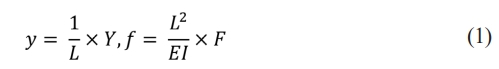
where L represents the characteristic length, E is the Young’s modulus of the material, and I =  is the moment of inertia of the beam cross-section, determined by its width B and height H, each have unit ‘m’.
The normalized transverse displacement of a single DPFM, y, due to a normalized applied force, f, is derived from equilibrium conditions and expressed as [10]:
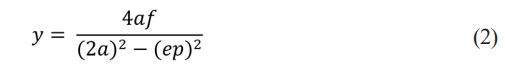
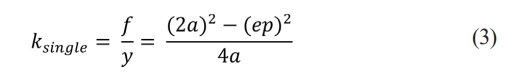
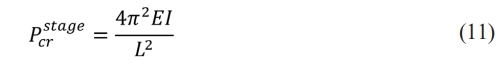
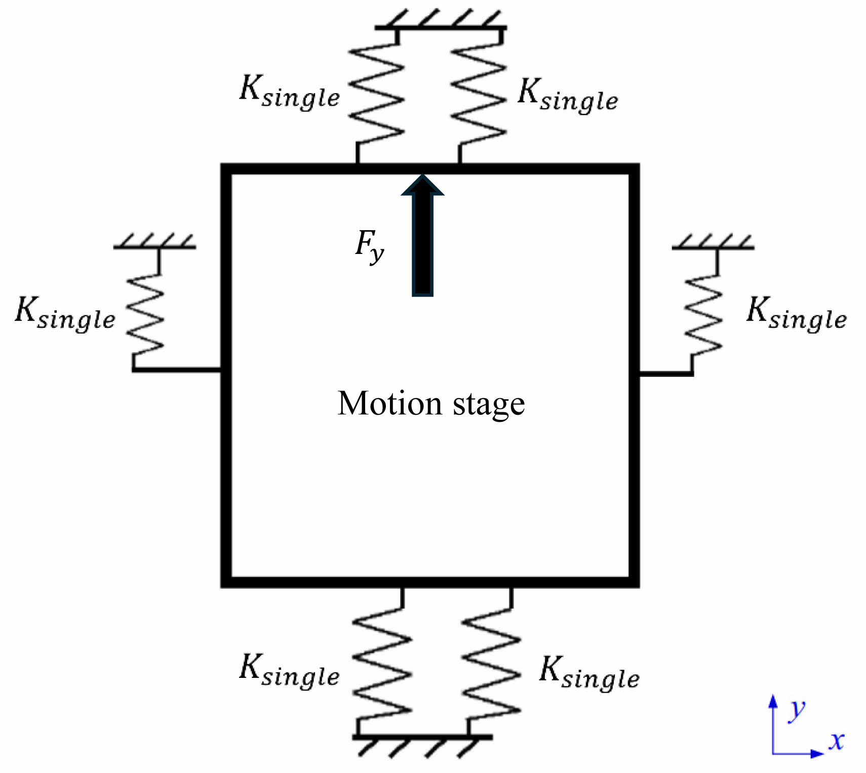
Here, the term a and e are coefficients reflecting the stiffness and geometric properties of the beam, and they have value of 12 and 1.2, respectively. The term p denotes the interaction force induced by the compliant motion stage, which is perpendicular to the actuation force, as illustrated in Fig. 1(a). The normalized stiffness for a single DPFM, ksingle, is subsequently expressed by rearranging (Equation (1)) with aid of Hooke’s law:
However, for calculations in actual values of stiffness, k is unnormalized as follows:
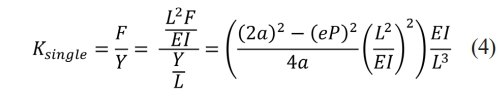
which can be simplified as Equation (5) with substituting the value of a and e:
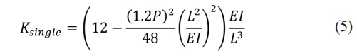
Mentioned earlier in Equation (2), the term ‘P’ represents the axial force applied to the structure. It directly affects the stiffness and displacement behaviour of the flexure structure non-linearly, producing parasitic motions. Specifically, positive P (introduced in tension) increases stiffness due to the load-stiffening effect, and negative P (introduced in compression) reduces stiffness and can eventually lead to buckling effect. However, due to the essence of the square term of P, the stiffness Ksingle decreases quadratically with increasing P, regardless the direction of the axial load. It is an inevitable consequence of the fact that in a single DPFM, since one stage is always in tension when another stage is in compression. To address this problem, utilizing symmetric configurations are essential to balance tension and compression forces in the structure, as the tensile load in one beam offsets the compressive load in the other, which will significantly minimize the overall effect of P on the system [10].
In order to simulate the stiffness model more efficiently, some assumptions are made to simplify the model:
1. The system operates under quasi-static conditions without significant dynamic or transient forces.
2. The transverse displacements are small relative to the beam length (y < 0.1 L) that will partially eliminate Elasto-Kinematic effects.
3. Rotational effects at the beam ends are negligible and do not significantly alter the axial or transverse force distribution.
As a conclusion of all assumptions, the value of P is approximated to be 5 for the consideration of both accuracy and simplicity of the model [10].
For a symmetric DPFM structure, the structure is constructed by connecting several pairs of single DPFMs in parallel. By assuming all flexures of DPFM have identical length, the stiffness of symmetric DPFM can be expressed as:
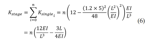
where i is an even continuous number with values 2, 4, 6, ..., n, representing the number of single DPFM employed in the compliant motion stage.
As clearly shown in Fig. 2, the stiffness model of the compliant motion stage is schematically and meticulously simplified to a free body diagram. In strict accordance with the analytical approach presented in Equation (2) for better visualization, a vertical force Fy is deliberately applied to the compliant motion stage in the Y-direction. Consequently, a distinct deformation in the y-direction with magnitude of Y is effectively generated in the motion stage. As illustrated in Fig. 3, the comprehensive structure design of the compliant motion stage is ingeniously formed by rotating and symmetrically organizing the single actuation unit (as presented in Fig. 1(c)), and subsequently connecting he symmetric configurations in a parallel manner. This approach is adopted to minimize any potential parasitic motions and achieve a higher level of motion accuracy.
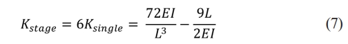
Consequently, the stage stiffness (Kstage) can be computed by Equation (7):
Critical load analysis
Buckling resistance in slender structural elements depends on the interplay of geometry, material properties, and boundary conditions. Similar instability phenomena have been analysed in porous ceramic structures under compressive loads, further emphasizing the need for robust buckling criteria in compliant stages. When a plate or beam is subject to compressive loading, its susceptibility to buckling can be examined through classical stability theory, which quantifies the critical stress σcr at which buckling initiates. For example, the governing equation for the compliant motion stage under uniaxial compression is given by [11]:
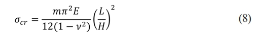
where E is Young’s modulus, n is Poisson’s ratio, h is the DPFM thickness, L is the DPFM’s in-plane dimension, and m is a dimensionless coefficient that depends on boundary conditions and aspect ratio. Analysing this formula reveals that as L/H increases, the term (L/H)2 diminishes rapidly, driving σcr to lower values and indicating a higher risk of buckling.
On this basis, one can decide how large the length-to-thickness ratio should be to maintain an acceptable level of structural safety. In the present design, a ratio of L/H= 0.05÷0.0005=100 has been deliberately selected to ensure the compliant motion stage can carry compressive loads without buckling prematurely. While a high length-to-thickness ratio of this degree enhance the performance of compliant motion stage, it also requires deeper consideration of residual stresses, and boundary details. In thin members, these factors are highly susceptible to reduce the buckling strength and thus produce elastic buckling under compressive loads [12].
Consequently, it is crucial to carry out anti-buckling analyse prior to mechanical design of the compliant motion stage. Buckling that appear on the compliant motion stage will greatly decrease the quality and efficiency of the desired motion transmission. Furthermore, it will also bring uncertainty to the deformation analysis, as the force variation in relation to corresponding deformation of a ductile material is likely to become non-linear after buckling is experienced. Thus, buckling effect should receive more attention in compliant motion stage design, and eliminated to the largest extend.
The critical load for the formation of buckling can be calculated:
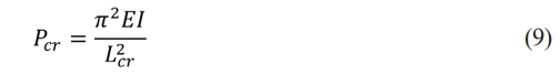
where Lcr (m) is the critical length and can be expressed as:

where k' is a specific constant, and its value varies from 0.5 to 2 depending on the different boundary conditions applied to the model. L represents the physical length of the structure [13]. For the instance in this paper, the schematic design that employs symmetric DPFM structure illustrated in Fig. 2(b) can be assumed as fixed-fixed structure, since all beams are constrained at the body of the compliant motion stage on both ends. Hence, the value of k' is set as 0.5 for this case [13], and the stage critical load Pcrstage is subsequently rewritten as:
Discussing the critical load is also important when it comes to the choice of VCMs, since an appropriately chosen VCM should be entirely eligible to actuate the compliant motion stage to reach the intended deformation, without the risk of damaging the compliant motion stage permanently by applying excessive amount of load to it. i.e. larger than Pcrstage.
With the given design requirement, the maximum deformation in one direction is Y = 5 mm, the actuation force for the VCM can be calculated using PyVCM = Kstage X Y. Consequently, the maximum actuation force of the VCM should be in the range of:
Material selection and parameters setting
Aluminum-7075 is a promising choice for the compliant motion stage due to its superior combination of high strength, lightweight properties, and good machinability, making it ideal for precision engineering applications. As a high-strength aluminum alloy, aluminum-7075 offers excellent resistance to deformation under load, ensuring that the compliant motion stage maintains its dimensional accuracy and structural integrity under both low and high stresses scenarios. Moreover, its’ good fatigue resistance further supports repeated use in dynamic applications, while its machinability allows for the precise fabrication of intricate components required in the design of compliant mechanisms. According to ASM Handbook, aluminum-7075 has ultimate tensile strength sUTS of 570 MPa, tensile yield strength syield of 505 MPa, density r of 2800 kg/m3, and Modulus of elasticity E of 72 GPa [14]. Although metals were selected in this study, ceramic components often encounter similar challenges in managing residual stresses. Jang reviewed the effects of machining-induced stress in ceramics, which reinforces the importance of residual stress consideration in compliant structure design.
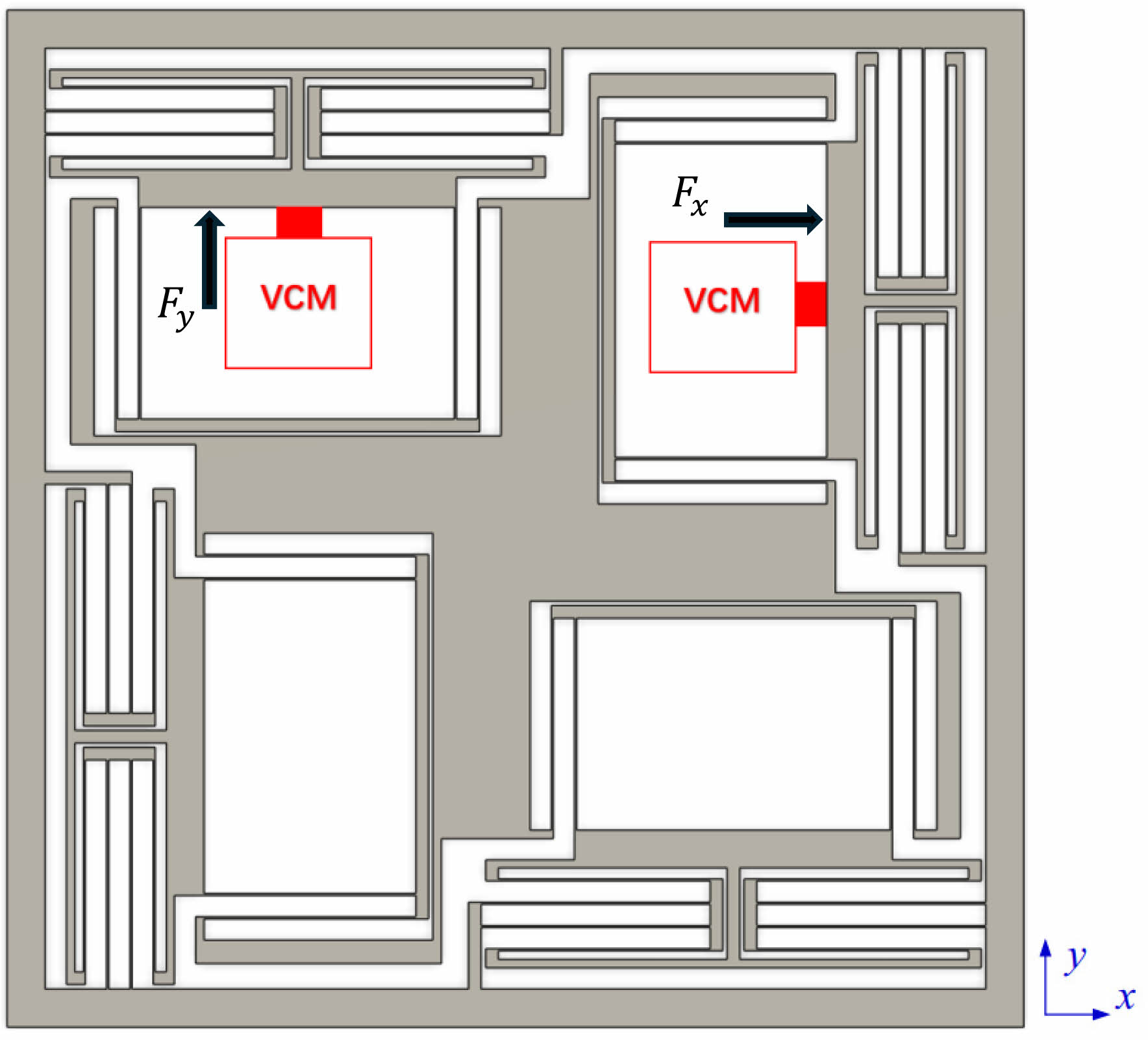
As a conclusion from the design criteria discussed earlier, some parameters are selected for the single actuation module, which are labeled and illustrated in Fig. 1(b) and (c), respectively: H = 0.0005 m, B = 0.001 m, L = 0.05 m, S = 0.0915 m, A1 = 0.005 m, B2 = 0.016 m, B1 = 0.074 m, and B2 = 0.086 m. The overall dimension of the compliant motion stage is 240 mm×240 mm×10 mm, and the complete design of the compliant motion stage is illustrated in Fig. 3. The red blocks represent the location of the VCMs, which are employed to actuate the stage in X and Y direction, respectively.
After substituting parameters into Equation (13), the limits of the maximum actuation force of each VCM should strictly locate between the maximum and the minimum force:
|
Fig. 1 Schematic drawing of DPFM and actuation unit in 2D and 3D. |
|
Fig. 2 Schematic drawing of stiffness model of the compliant motion stage. |
|
Fig. 3 Compliant motion stage design with the maximum deflection of 5 mm. |
The FEA analysis is carried out using Ansys Mechanical APDL. An adequate mesh in ANSYS Mechanical is vital for accurate and reliable simulation results. It ensures precise representation of geometry, captures stress concentrations, and resolves gradients in critical areas like boundaries or sharp edges. A high-quality mesh promotes convergence, reducing numerical errors and enhancing computational efficiency. A finer mesh is applied to the areas where the stresses are concentrated i.e. DPFMs in actuation module, while other parts are employed with coarser mesh to balance the overall accuracy and computational cost. Specifically, DPFMs are meshed at element size of 0.00025 m, which is twice smaller than the width of single spring element of DPFM.
Motion errors
Discussed in the previous section, the actuation force to reach a deformation of 5 mm is 20 N. With the aim to reach high resolution of data, a total number of 80 steps of forces ranging from 0.25 N to 20 N are used for simulation. Each step has an incremental force of 0.25 N. Afterwards, the simulated results are strictly compared with the calculated data. Specifically, the percentage difference of the deformation induced by actuation is analyses, and it can be calculated for each increment.
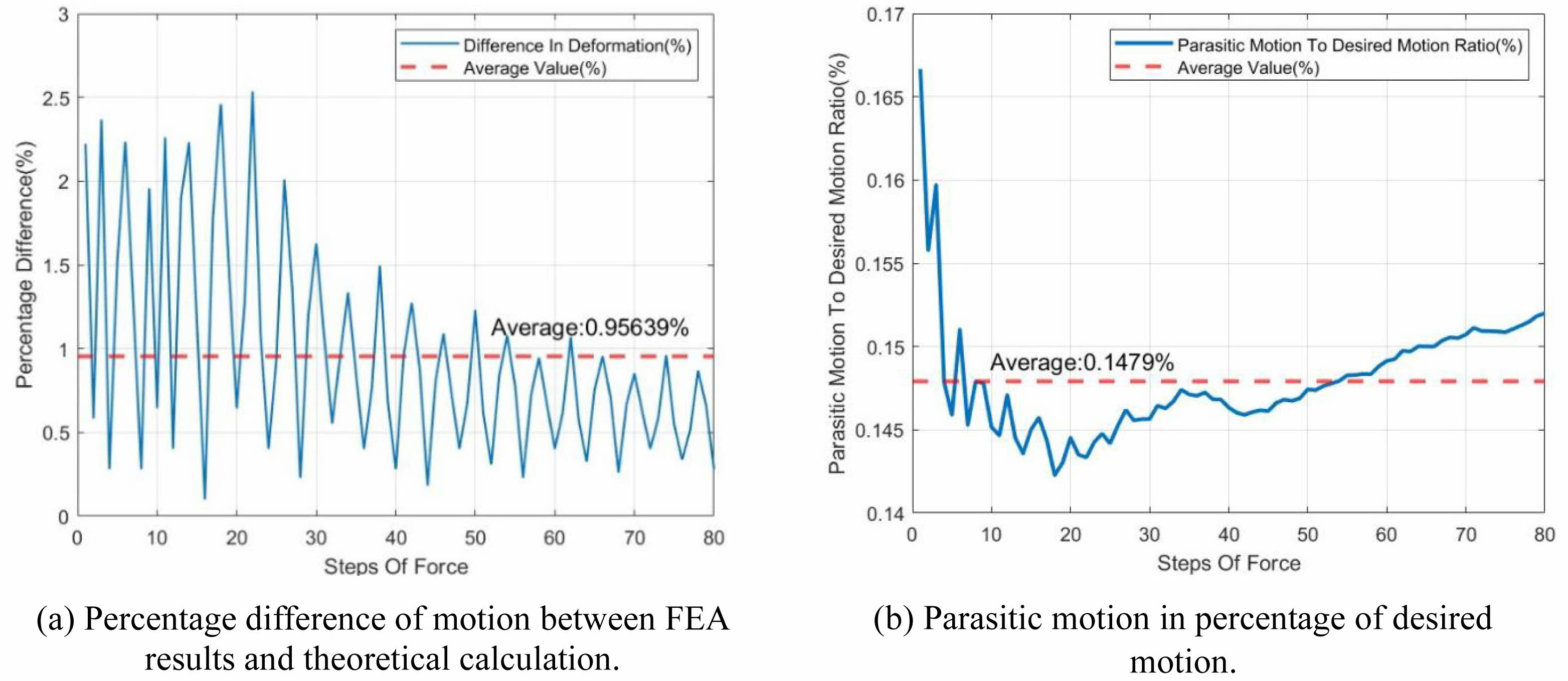
Clearly observed in Fig. 4(a), the graph indicated an overall downward trend in the level of percentage differences as the forces of the steps were increased. The averaged value of percentage difference is 0.956%, and the peak value is 2.535% which appears when the Force applied equals to 2.25 N.
In more specific terms, initially, between steps 0 and 20, the percentage differences all peaked above 2%, however, the fluctuation of the values was also very significant, ranging from 2% to 0.1%. As the steps increased from 20 to 60, the peak percentage difference value gradually declined to approximately 1%, and the fluctuation also decreased to a lower range. Finally, as the steps increased up to 80, the peak dropped to a more stable value slightly below the average line, and the spread of the percentage difference data also reduced to a lower range of around 0.5%.
The parasitic motion is mainly caused by the coupling of motion at the transverse direction, which will largely affect the motion quality of the compliant motion stage. Down to this problem, a deformation probe is employed at the centre of the motion stage, where is also the centre point of the compliant motion stage itself, to record the transverse deformation that is perpendicular to the actuation force. Shown in Fig. 4(b), a distinct decrease in parasitic motion to desired motion ratio at the lower steps of force, which then gradually increases and stabilizes its magnitude at higher force steps. The average parasitic motion to desired motion ratio is 0.148%, which indicates that the magnitude of parasitic motion is 0.148% of the magnitude of desired motion. Therefore, the parasitic motion is sufficiently small to draw the conclusion that the motion of compliant motion stage is ‘fully decoupled’ in X and Y directions.
Stress and strain analysis
Equivalent stress and strain enable the representation of any arbitrary three-dimensional state as a single positive value. It is a key component of the maximum equivalent stress failure theory, which is used to predict yielding in ductile materials. [15] In Ansys Mechanical APDL, the equivalent stress and strain, which is also referred to Von-Mises stress and strain, are computed as Equation (15) respectively [16]:
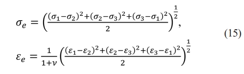
where σi and εi (i = 1, 2, 3) represent the principal stress and strain, respectively, ν is the Poisson ratio of the material.
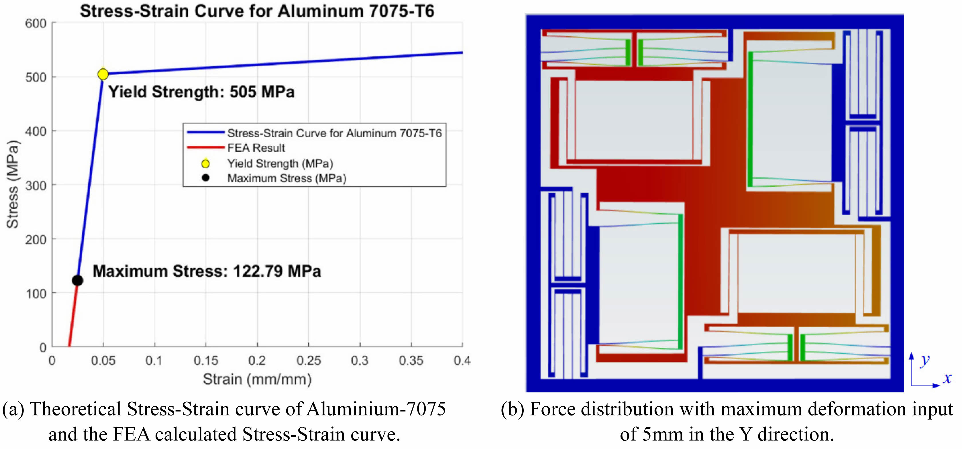
The theoretical mechanical properties of Aluminium
-7075 [14] are compared with simulation results, as represented by the blue and red curves in Fig. 5(a). The stress-strain analysis result in Ansys demonstrates that the maximum stress experienced by the compliant motion stage is 122.79 MPa, which is significantly below the yield strength of Aluminum-7075 i.e. 505 MPa, as highlighted in black and yellow dot respectively in Fig. 5(a). The result reveals that the compliant motion stage is operating exclusively within the elastic deformation regime, preventing the onset of plastic deformation. Such behaviour is beneficial for ensuring the consistent performance of the structural integrity and durability of the beam under repeated loading. Furthermore, the lower value of the maximum stress experienced by the compliant motion stage also indicates that the buckling effect does not exist mathematically. It is also validated by the FEA result shown in Fig. 5(b), with no visual buckling effect on the compliant motion stage. Prior studies on Al₂O₃ ceramic scaffolds under structural loading have similarly demonstrated elastic stability and low strain localization, supporting the analytical assumptions made in this study.
Modal analysis
The modal analysis is a critical tool in the design and optimization of the compliant motion stage, as it offers essential insights into the dynamic behaviour of the system. Modal analysis facilitates the prediction of potential resonance conditions that could potentially undermine the compliant motion stage's stability and performance during operation by identifying the natural frequencies and mode shapes. It is important to discuss the dynamic characteristics of a compliant motion stage that is equipped with compliant mechanisms, as having sets of appropriate natural frequencies guarantees high structural integrity, reduces parasitic vibrations, and preserves precision during repetitive movements of the compliant motion stage.
The natural frequency refers to the frequency at which the system tends to vibrate when disturbed from its equilibrium position without any external forces acting on it. As a fundamental property of the compliant motion stage, it is determined by the system's mass and stiffness and undoubtedly plays a crucial role in the dynamic behaviour of the compliant motion stage. The natural frequency f of the compliant motion stage can be computed with Equation (16) [17]:

where Meq represents the equivalent mass of the compliant motion stage, and it can be further expressed as follow [18]:

where M is the mass of the motion stage, meq denotes the equivalent mass of the actuation module.
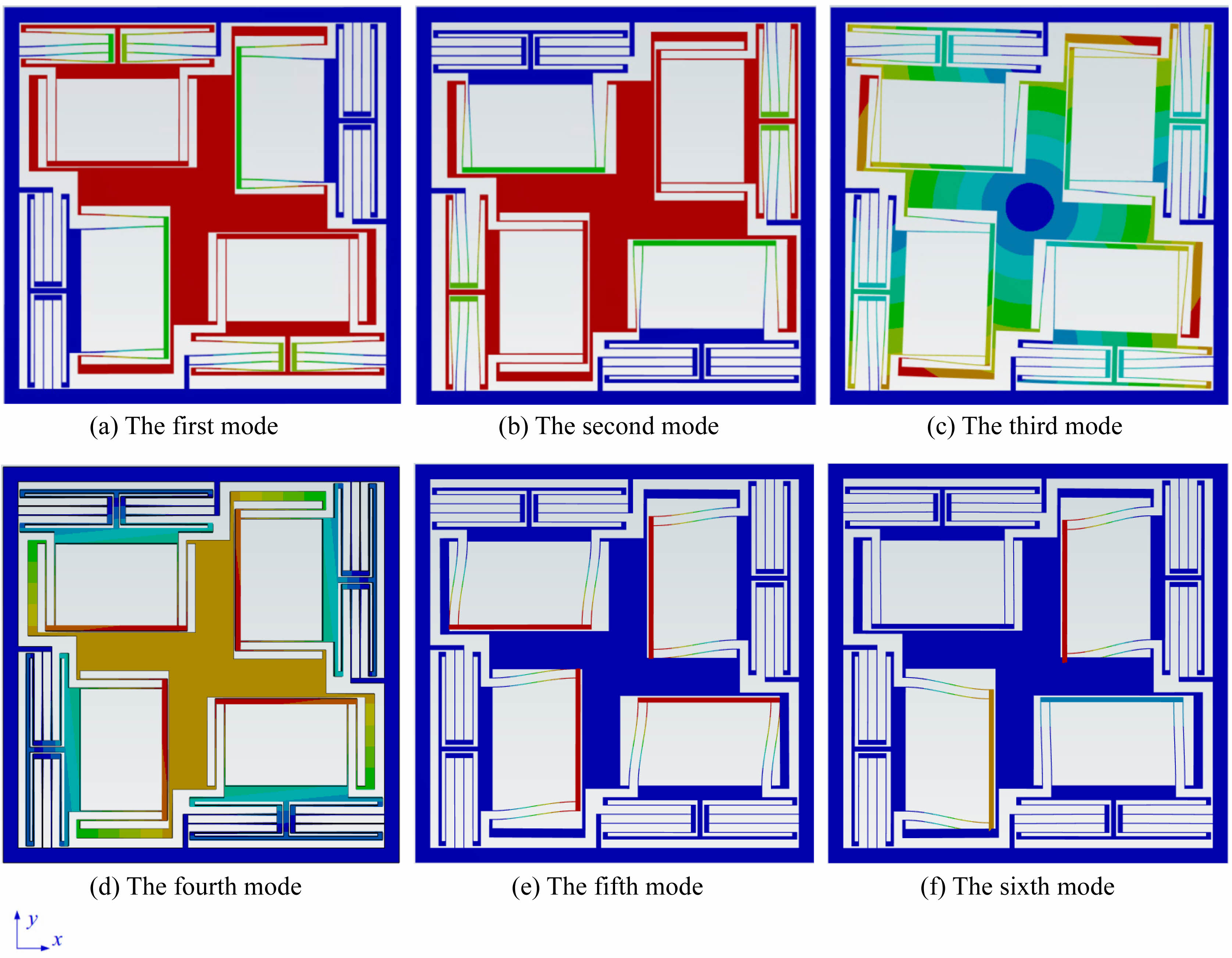
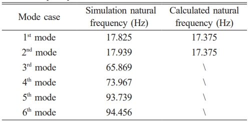
Modal analysis is carried out using Ansys, computed with integrated Mechanical APDL solver. The first 6 modes of the compliant motion stage are presented in Fig. 6, with corresponding values of natural frequencies are listed in Table 1. Among all scenario, the compliant motion stage tends to oscillate in the X-Y plane except of the fourth mode [19, 20], regardless the specific part that involves in the motion. Simulation result reveals that the compliant motion stage will oscillate vertically about the X-Y plane in the fourth mode, with natural frequency of 73.967 Hz, as illustrated in Fig. 6(d).
Despite the various vibrate motions, the first two modes of vibrating are deliberately discussed in this paper, as the compliant motion stage is designed to experience deformation at X and Y axis only. Distinguished by level of colour ranging from blue to red in Fig. 6(a) and (b), the middle part, which is referred as the ‘motion stage’ and coloured in red, experiences the largest deformation. In the same figure, the blue coloured regions represent the part that deform the least in the compliant motion stage during oscillation, and rest of the parts locates where ‘actuation modules’ are defined.
Consequently, the equivalent mass Meq of the compliant motion stage for the first two modes is eligible to be calculated correspondingly by Equation (17), using equation m = ρV, where V is the volume of each part:

Thus, calling back Equation (7) about the stage stiffness Kstage, the natural frequency for the first and second mode of oscillation can be calculated by substituting calculated Meq and Kstage into Equation (14). Shown in Table 1, the natural frequency results with a constant value of 17.375 Hz for the first and second mode. This is down to the fact that the structural design of the compliant motion stage is symmetrical about the motion axis, the behaviour of motion is thus identical for both X and Y directions, as they share the same value of Meq and Kstage. Compared to the simulation results, the mathematical model only produces 2.524% and 3.144% difference for the first and second mode, respectively. These deviations confirm that mesh convergence and symmetry assumptions were sufficient to eliminate major modal discrepancies due to numerical artefacts.
|
Fig. 4 Comparison of data obtained from FEA result. |
|
Fig. 5 FEA result of stress and strain data and force distribution under 5mm deformation. |
|
Fig. 6 Ansys modal analysis results for the first to the sixth mode. |
|
Table 1 Data of FEA simulated natural frequency and calculated natural frequency |
By adopting a symmetric double parallelogram flexible module (DPFM) as the main structural component, the compliant motion stage achieves a high degree of axial decoupled motion while minimizing parasitic errors. This paper specifically focuses on the effectiveness of systematic stiffness modelling and optimization.
Aluminium 7075-T6 was selected for its superior strength-to-weight ratio and fatigue resistance. To preliminarily assess the stage's performance under cyclic conditions, finite element simulations were performed across 50 continuous cycles using 80 incremental force steps ranging from 0.25 N to 20 N. The difference in stage deformation between the first and 50th cycle was recorded as 0.000003%, indicating negligible fatigue-related degradation within the elastic regime. While long-term fatigue testing has not yet been conducted, these results suggest structural stability under repeated loading. Future work will involve experimental fatigue evaluation under extended dynamic operation. The stress analysis shows that the maximum stress borne by the structure is 122.79 MPa, which is far lower than the yield strength of the material (505 MPa), ensuring that the micro-motion platform is completely within the elastic deformation range even under the maximum load. The significant margin between the maximum stress and the yield strength ensures safety and reliability, even under variable and dynamic loading scenarios. In addition, the platform exhibits good buckling resistance under compressive loads through an optimized length-thickness ratio (L/H = 100), which further demonstrates the robustness of its structure.
Notably, as represented in Fig. 4(a), the peak value reaches 2.535% when the actuation force equals 2.25 N. And the oscillatory nature of the percentage difference highlights the minor deviations in accuracy throughout the force range, which is likely due to numerical approximations in the FEA model or other minor nonlinearities that were not accounted for in the theoretical calculation. However, the system still demonstrates a high degree of accuracy of motion not only due to its low figure of the average percentage difference i.e. 0.956%, but the significant decoupling performance also validates the reliability and precision of motion with results that the parasitic motions is only 0.148% of desired motion.
In the dynamic performance evaluation, the modal analysis shows that the theoretical natural frequencies of the first and second modes are both 17.375 Hz, corresponding to the X and Y axis motion, which the differences to the FEA result are 2.524% and 3.144% respectively. It can be observed from Fig. 6 and Table 1 that the natural frequencies of the compliant motion stage of the first and the second mode (in the direction of moving degrees of freedom) are notably different from those ranging from mode 3 to 6, suggesting that the platform possesses excellent dynamic performance and strong anti-interference performance in the direction of non-degrees of freedom. In addition, the average parasitic motion of 3.394 µm indicates that the platform is able to maintain the motion mass and axial decouple ng performance throughout the travel range. Compared with the existing designs such as Chen et al. and Wang et al. [7, 8], this study has achieved significant progress in stiffness optimization, motion decoupling, and structural performance.
Nonetheless, some limitations should also be considered, including the choice of VCM and the fact the compliant motion stage has not yet been tested in real scenes under variable environmental conditions with integration of VCM. The stiffness is deliberately designed to be low because the VCM has a relatively low actuation force. However, it compensates for this by providing a large displacement and achieving high accuracy. This unique combination of features makes VCM an attractive option in certain applications. Also, the maximum actuation force of VCM should locate between 19.96 Nto 116.79 N in order to provide sufficient deformation to the compliant motion stage. The subsequent and crucial step is to conduct comprehensive tests of the compliant motion stage in the actual real-world environment. This testing phase is essential to verify the performance, reliability, and functionality of the compliant motion stage under real operating conditions, enabling any necessary adjustments or optimizations to be made to ensure its optimal performance and suitability for the intended purpose. Future work should focus on further on integrating advanced feedback control systems and verifying the performance of the design in dynamic and real-world applications.
Although this study focused primarily on ideal loading conditions and nominal geometry, real-world implementations inevitably introduce variability due to manufacturing tolerances and assembly imperfections. To address this, future work will involve a detailed tolerance analysis using statistical and worst-case scenarios to evaluate the impact of deviations in flexure width, hinge spacing, and actuator misalignment on parasitic motion and decoupling accuracy. Additionally, high-cycle experimental fatigue testing under realistic operating conditions will be undertaken to confirm the long-term structural integrity observed in simulation.
To sum up, this paper designed, analysed, and validated a high-precision compliant motion stage with stroke range of ± 5 mm in both X-axis and Y-axis directions to meet the increasing demand for high-precision motion systems in semiconductor manufacturing, optical alignment, and biomedical devices. It has successfully achieved decoupled motion and minimizing parasitic errors through the innovative use of symmetric DPFM. The low parasitic error and average deformation difference both successfully verify the symmetry and stability of the design. The selection of Aluminium-7075, known for its high strength-to-weight ratio and excellent fatigue resistance, enhances the structural integrity of the compliant motion stage under both static and dynamic loads. FEA results validate the theoretical predictions, with an average motion difference of 0.956% and a parasitic motion to desired motion ratio of only 0.148%, which proves the compliant motion stage is fully decoupled in both X and Y directions. Modal analysis further demonstrates the stage’s robust dynamic performance, with the first and the second mode natural frequencies closely matching theoretical values, exhibiting only minor deviations i.e. 2.524% and 3.144%, respectively. These results indicate strong motion stability, and the large difference in the natural frequencies of desired motion and that of other degree of freedoms reveals resistance to undesired vibrations. FEA result data of stress and strain also validates the reliability of the design, with a maximum stress of 122.79 MPa under 5 mm of deformation, well within the elastic range of the material's yield strength of 505 MPa, ensuring long-term reliability. The symmetric configuration also contributes to robustness against minor misalignments and load asymmetries, though experimental testing is required to quantify these effects. Furthermore, the influence of manufacturing tolerances on parasitic motion will be investigated through statistical tolerance analysis.
The choice of VCM should be carefully contemplated as well, with the requirements of at least a ±5 mm stroke range, and the actuation force should range from 19.96 Nto 116.79 N. FEA results, while accurate in simulations, may not fully account for these environmental variables. Testing in practical scenarios is essential to verify the design’s reliability and adaptability. Therefore, the future steps of this study should focus on manufacturing the compliant motion stage and carrying out experiments by integrating feedback control systems in order to effectively analyse the performance of the compliant motion stage.
The author(s) declared no potential conflicts of interest with respect to the research, author-ship, and/or publication of this article.
The datasets used and/or analyzed during the current study are available from the corresponding author on reasonable request.
The author(s) received no financial support for the research, authorship, and/or publication of this article.
- 1. Z. Zhang, D. Zhang, H. Zheng, T. Huang, and Y. Xie, Proc. Chinese Control Conference (2019) 1637-1642.
-

- 2. S. Awtar, J. Quint, and J. Ustick, J. Mech. Robot. 13[1] (2021) 015001.
-
- 3. P.P. Raut, A.S. Rao, S. Sollapur, and D.D. Baviskar, Int. J. Interact. Des. Manuf. 18[7] (2024) 4397-4408.
-
- 4. J. Perdigao, P. Lambrechts, and G. Vanherle, Am. J. Dent. 13 (2000) 3D18D.
- 5. A.S. Algamili, M.H.M. Khir, J.O. Dennis, A.Y. Ahmed, S.S. Alabsi, S.S. Ba Hashwan, and M.M. Junaid, Nanoscale Research Letters. 16 (2021) 1-21.
-
- 6. Y. Qiao, T. Zhao, and X. Gui, CES Trans. Electr. Mach. Syst. 6[3] (2022) 269-278.
-
- 7. X. Chen, Y. Li, Y. Xie, and R. Wang, Mech. Mach. Theory. 167 (2022) 104527.
-
- 8. C. Jiao, Z. Wang, B. Lv, G. Wang, and W. Yue, Appl. Sci. 10[23] (2020) 8336.
-
- 9. S.B. Sollapur, P.M. Waghmare, M. Patil, and S. Deshmukh, J. Eng. Sci. Technol. 16[2] (2021) 1416-1425.
- 10. S. Awtar, A.H. Slocum, and E. Sevincer, Journal of Mechanical Design. 129[6] (2007) 625-638.
-
- 11. Z.P. Bazant and L. Cedolin, Aeronaut. J. 116[1176] (2012) 218-219.
- 12. Q. Xu, IEEE Trans. Robot. 28[2] (2011) 478-491.
-
- 13. N. Lobontiu, Compliant Mech.: Des. Flexure Hinges, CRC Press (2002).
-
- 14. ASM Handbook Committee, ASM International. 2 (1990).
-
- 15. L. Xue, Eng. Fract. Mech. Mech. 76[3] (2009) 419-438.
-
- 16. ANSYS Inc, (2025) Online: https://ansyshelp.ansys.com/account/secured?returnurl=/Views/Secured/corp/v242/en/wb_sim/ds_Equiv_Stress.html
- 17. G. Wu, G. Li, Y. Yang, and Y. Wei, Microsyst. Technol. (2024) 1-22.
-
- 18. S.S. Rao, Prentice Hall, 5 (2011)
- 19. J.I. Jang and J. Ceram. Process. Res. 10[3] (2009) 391-400.
-
- 20. N.C. Fan, Y.Y. Chen, K.Y. Chen, W.C.J. Wei, B.H. Liu, A.B. Wang, and R.C. Luo, J. Ceram. Process. Res. 18[9] (2017) 676-682.
-
 This Article
-
2025; 26(4): 596-605
Published on Aug 31, 2025
- 10.36410/jcpr.2025.26.4.596
- Received on May 9, 2025
- Revised on Jun 20, 2025
- Accepted on Jul 3, 2025
Services
- Abstract
introduction
structural design and modelling of the compliant motion stage
fea verification
discussion
conclusion
- Conflict of Interest
- Data sharing agreement
- Funding
- References
- Full Text PDF
Shared
Correspondence to
- Xinyu Liu
-
Department of Mechanical Engineering, University College London, London, WC1E 6BT, The United Kingdom
Tel : +44-07944341260 - E-mail: zcemxl1@ucl.ac.uk
Clean-Energy Research Institute(CRI), Hanyang University, 222, Wangsimni-ro, Seongdong-gu, Seoul, 04763, Korea
E-mail: jcpr@hanyang.ac.kr