


- Comparative study of incoloy 825 mechanical properties and microstructure via FSW with and without carbon nanotubes
Varalakshmi Penugondaa,b, Murali Govindarajana,* and Vijaya Kumar Bongaralab
aDepartment of Mechanical Engineering, Koneru Lakshmaiah Education Foundation, Guntur Andhra Pradesh, 522502, India
bDepartment of Mechanical Engineering, Guru Nanak Institute of Technology, Hyderabad, Telangana, 501506, IndiaThis article is an open access article distributed under the terms of the Creative Commons Attribution Non-Commercial License (http://creativecommons.org/licenses/by-nc/4.0) which permits unrestricted non-commercial use, distribution, and reproduction in any medium, provided the original work is properly cited.
This study investigates the mechanical properties and microstructure of Incoloy 825 alloy joints made using friction stir welding (FSW), with and without carbon nanotube (CNT) reinforcement. FSW was performed at different tool rotation speeds (300-500 rpm) and welding speeds (20-100 mm/min). The best results were achieved at 400 rpm and 30 mm/min. Microstructural analysis using scanning electron microscopy (SEM) and energy-dispersive X-ray spectroscopy (EDX) showed that CNTs were evenly spread in the stir zone without forming clusters. X-ray diffraction (XRD) and Raman spectroscopy confirmed that there were no major changes in the alloy's phases, keeping its original structure intact. Adding CNTs improved the tensile strength and hardness of the joints by creating finer grains through dynamic recrystallization. The CNT-reinforced joints showed better mechanical properties due to effective load transfer and grain refinement. This study shows that adding CNTs during FSW is a useful way to improve the mechanical properties of Incoloy 825 joints, making them suitable for advanced engineering applications.
Keywords: Carbon nanotubes, Incoloy 825 alloy, Friction stir welding, Reinforcement strategy.
Friction Stir Welding (FSW) is a solid-state welding process that uses a non-consumable rotating tool to generate heat and plastic deformation in the workpiece, creating a bond between two pieces of metal. The process is characterized by the use of a cylindrical shoulder and a profiled probe which are pressed into the workpiece. The shoulder is then rotated at high speed and the probe is moved forward to create a forging action which generates heat and plastic deformation [1, 2]. While FSW is normally carried out without the use of a filler material, reinforcing agents, such as nanoparticles, can be introduced via techniques such as groove filling. This adaption enables the creation of improved composite materials [3]. FSW process is an advantage over traditional fusion welding processes, such as gas tungsten arc welding (GTAW) and gas metal arc welding (GMAW), which melt the metal, making it more susceptible to cracking, warping, and other forms of damage [4].
Incorporating nanoparticles in FSW is a strategy to address many of the challenges associated with traditional welding processes. Nanoparticles enhance the FSW process by serving as nucleation sites for dynamic recrystallization, resulting in finer grain structures and enhanced mechanical characteristics [5]. Their large surface area improves dispersion within the stir zone, increasing load transmission and lowering stress concentrations. This results in improved tensile strength, hardness, and wear resistance. Additionally, nanoparticles increase thermal stability by minimizing grain development and preserving the weld's [6]. Traditional welding processes frequently experience problems such as grain coarsening, residual tensions, poor mechanical qualities, restricted material compatibility, decreased corrosion resistance, and excessive energy consumption [7]. As a solid-state process, FSW overcomes these issues by working below the melting point. Nanoparticles increase grain refinement, stress distribution, and weld strength by limiting fracture propagation. These produces weld junctions with excellent mechanical qualities, structural integrity, and long-term endurance [8]. Furthermore, nanoparticles promote better bonding in various metal joints, increase corrosion resistance, and enhance energy efficiency. These developments make FSW an important technology for making high-quality, dependable welds. The method is frequently used in industries like as aerospace, automotive, railway, marine, and energy, where the strength and integrity of welded connections are essential. Manufacturers may improve weld quality, performance, and reliability in critical applications by combining FSW with nanoparticles [9, 10].
Incoloy 825 is a nickel-based alloy that contains iron, chromium, nickel, and molybdenum, as well as small amounts of other elements. It is known for its excellent corrosion resistance in a wide range of environments, including acidic and alkaline conditions, as well as high resistance to stress corrosion cracking and pitting corrosion. Additionally, it has high strength and toughness, making it suitable for use in a variety of demanding applications like Oil and gas industry for piping, valves, and other equipment that is exposed to harsh environments, such as high temperatures and corrosive fluids. Chemical processing equipment, including heat exchangers, tanks, and piping, is employed across diverse chemical environments owing to its exceptional corrosion resistance. In marine engineering applications, it is used for items like propellers, shafts, and other underwater equipment exposed to seawater and challenging marine environments. In nuclear industry as a material of choice for piping, vessels, heat exchangers, and other components due to its excellent corrosion resistance and strength [11-14]. In the past few years, numerous researchers have explored the welding of Incoloy 825 super alloy. Kangazian et al. [15] utilized three filler wires, namely ER219, ERNiFeCr-1, and ERNiCrMo3, in the multipass gas tungsten arc welding process to fabricate Incoloy 825 joint. Research findings indicate that employing three distinct filler materials can result in joints that closely approximate the hardness values of the Incoloy 825 base metal. Shien Liu et al. [16] employed electron beam welding for joining Incoloy 825. The study focused on assessing the mechanical performance of the joints under various conditions, revealing that the mechanical characteristics of the weld zone (WZ) and base metal (BM) were nearly identical. Based on the literature mentioned above, numerous conventional welding methods have been employed to enhance the mechanical properties of Incoloy 825 alloy. However, need to exploring novel welding techniques, such as FSW, and methodologies to further enhance the mechanical properties.
Numerous studies on the friction stir welding of Ni-based alloys have been published in recent times. Song et al. [17] employed friction stir welding on Inconel 625 alloy to enhance weld strength and microhardness properties. Lemos et al. [18] reported grain refinement and increased microhardness values in the weld zone when utilizing friction stir welding on Inconel 625. Additionally, Song et al. [19] found reduced grain size and higher hardness in the stir zone of Inconel 718 alloy compared to the base metal. Kangazian et al. [20] achieved a bonding between Incoloy 825 and stainless steel through friction stir welding. The investigation revealed that the primary stir zone comprised equiaxed recycled austenite and ferrite grains, and the mechanical properties of the welded joint closely resembled that of the substrate. The potential benefits of utilizing friction stir welding for reinforcing and refining the grain structure of nickel alloys have garnered recent attention from researchers [21]. Nevertheless, as of now, there is no reported work on the friction stir welding of Incoloy 825 with carbon nanotubes (CNTs).
Carbon nanotubes (CNTs) are cylindrical structures made of carbon atoms that have unique mechanical, thermal, and electrical properties. CNTs can be found in two forms, single-walled and multi-walled. Single-walled carbon nanotubes (SWCNTs) have one layer of carbon atoms and are typically smaller in diameter, while multi-walled carbon nanotubes (MWCNTs) are made up of multiple concentric layers of carbon atoms and are usually larger in diameter. They have a diameter of a few nanometres and can be several micrometres long. CNTs have a high strength-to-weight ratio and a Young's modulus (stiffness) that is several times higher than that of steel. This makes them ideal for use in lightweight, high-strength composites. CNTs have a high thermal conductivity, which makes them useful for thermal management applications, such as heat sinks, thermal interface materials, and thermal-electrical generators. CNTs have a high electrical conductivity, making them useful for electrical applications, such as conductive coatings, electronics, and energy storage. CNTs have a high aspect ratio, which means that they are long and thin. This makes them ideal for use as reinforcement in composites, as they can provide a high degree of mechanical reinforcement while maintaining a low weight.
There has been a significant amount of research on the use of carbon nanotubes (CNTs) as reinforcement in metallic matrix composites (MMCs) in recent years. CNTs have been shown to be effective at reinforcing a variety of metal alloys, including aluminum, copper, and nickel-based alloys. The addition of CNTs to metallic alloys can lead to improved mechanical properties such as increased strength, stiffness, and toughness, as well as improved thermal and electrical conductivity. The CNTs act as reinforcement by providing an efficient load transfer between the matrix and the CNTs, which results in an overall improvement in the properties of the composite. In addition to improved mechanical properties, the use of CNTs as reinforcement in MMCs has also been shown to improve corrosion resistance. CNTs have a high aspect ratio and a high surface area, which makes them effective at preventing corrosion by providing a barrier between the matrix and the environment. Additionally, the CNTs can act as cathodic inhibitors, which can slow down the corrosion rate of the matrix. There have been many studies that have been done on CNT reinforced metallic matrix composites, and the results are promising. The CNTs have been shown to be effective at reinforcing a wide variety of metal alloys, which can lead to improved mechanical properties and corrosion resistance. However, more research is still needed to fully understand the behaviour of CNT-reinforced MMCs and to develop the best methods for fabricating and processing these materials [22-27].
In recent research conducted by Se Eun Shin and their team, the advantages of incorporating carbon nanotubes (CNTs) into aluminum (Al) composites using friction stir welding (FSW) have been explored. This composite demonstrated a remarkable two-fold improvement in the balance between strength and ductility compared to the base metal [28]. F. Khodabakhshi et al. reported, the exceptional advantages of employing carbon nanotubes, in the context of friction-stir processing (FSP) of aluminum-magnesium (Al-Mg) alloys were thoroughly explored. The researchers achieved a homogenous distribution of these reinforcing agents throughout the aluminum matrix, enhanced the material's mechanical properties, with notable improvements in yield strength and Vickers hardness [29]. Bolyu Xiao and their team undertook a noteworthy investigation focused on the advantageous use of carbon nanotubes (CNTs) in friction stir welding (FSW), particularly in the context of joining previously treated Al-Cu-Mg composite plates. Remarkably, their study demonstrated an impressive joint efficiency of 87%, a testament to the effectiveness of incorporating CNTs into the FSW process [30].
The use of CNTs as a reinforcement material in Incoloy 825 sheets can enhance the properties of the material such as mechanical properties. In this research work, the feasibility of using friction stir welding to join Incoloy 825 sheets reinforced with carbon nanotubes has been investigated. Different zones within the FSW samples, grain refinement and effective dispersion of CNT within the stir zone were evaluated using optical microscopy, scanning electron microscopy (SEM), and energy-dispersive X-ray spectroscopy (EDAX). CNT-reinforced Incoloy 825 phase stability (changes in the phase) and structural defects in CNTs during friction stir welding are discussed. The mechanical properties of the FSW samples of Incoloy 825 were compared with and without CNTs.
Materials
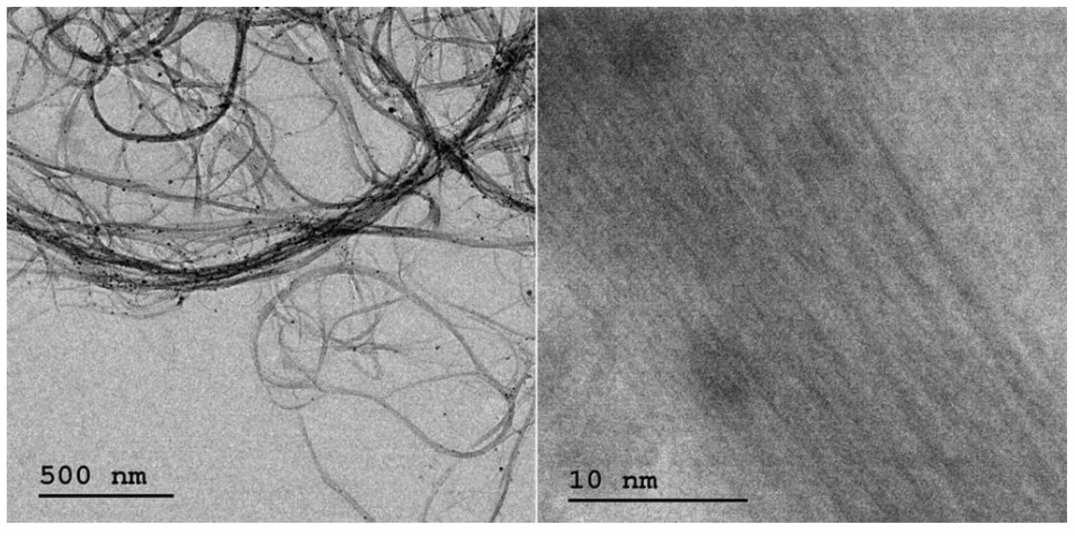
Incoloy 825 alloy sheets were used for friction stir welding, with dimensions of 105 × 80 × 2 mm. The composition of Incoloy 825 is provided in Table 1. CNTs were employed as reinforcement materials, with >85 wt % carbon, mean diameter of 1.8 ± 0.3 nm, length of CNT > 5 µm, BET surface area ~490 m2/g, and bulk density of 0.1 gm/cm3. The CNTs were characterized using TEM shown in Fig. 1.
Experimental methods
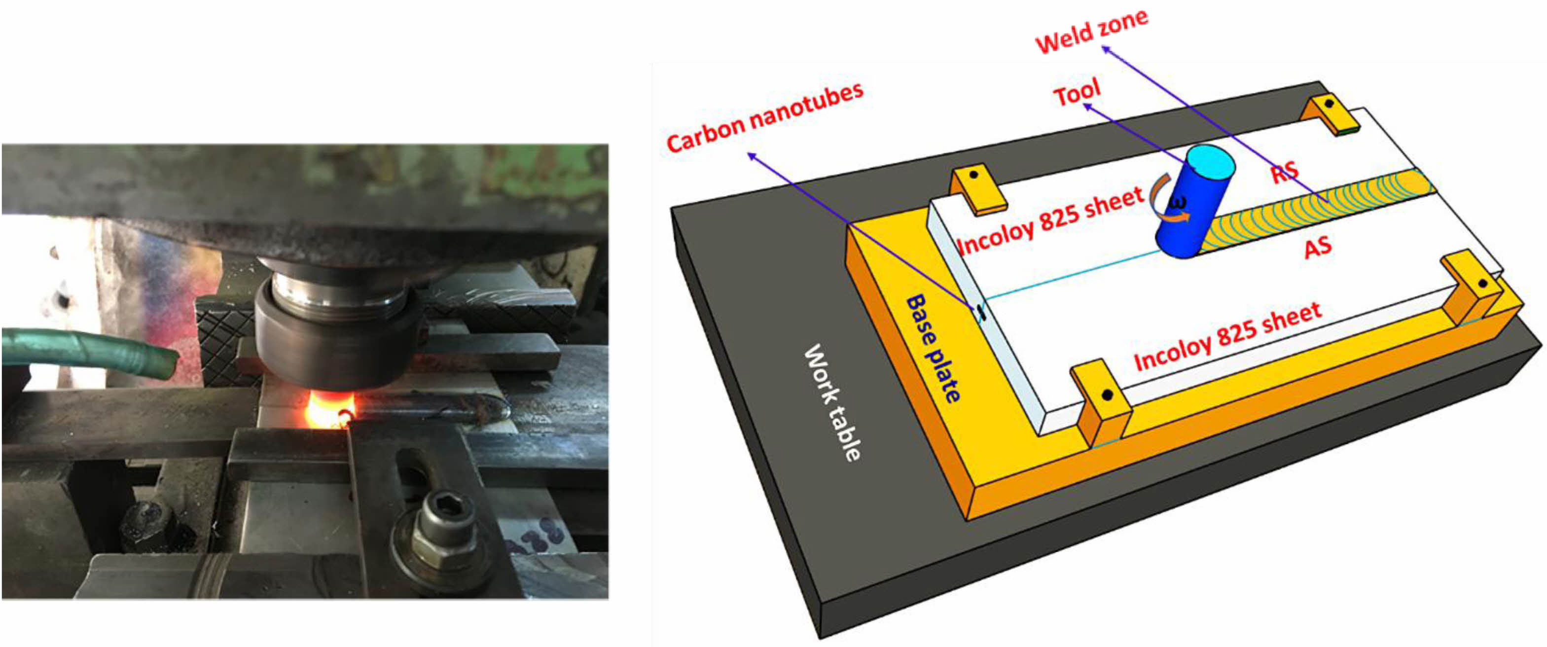
A groove (0.5 mm depth and 0.5 mm breadth) was machined at the faying surface of the Incoloy 825 alloy to introduce the CNTs into the stirred area. The integrated groove was designed to trap 50 milligrams of CNTs between the specimens, ensuring no leakage during the welding process. Fig. 2 Demonstrated experimental FSW setup and schematic perspective of the CNTs powder groove for friction stir welding. Rotational speed is known to influence grain refinement in FSW, and in this investigation, various rotational speeds of 300 rpm, 400 rpm, and 500 rpm were used. The Tungsten carbide cobalt (WC-Co) tool had a pin diameter of 6 mm, a shoulder diameter of 18 mm, and a pin length of 1.9 mm. The optimum rotational speed and tool traverse speed were found to be 400 rpm and 30 mm/min, respectively, with a tool tilt angle of 3 degrees. Inert gas (Argon gas) was used to counter surface oxidation during welding. Microstructure analysis was performed using polished specimens that were etched with a solution of 97 ml of hydrochloric acid, 2 ml of nitric acid, and 1 ml of sulphuric acid. The interfacial microstructure was further examined using an optical microscope (Olympus (BX41M)), Field Emission Scanning Electron Microscope (FESEM, Gemini 500 (M/s Carl Zeiss) and EDS (Energy Dispersive Spectroscopy). XRD and Raman analyses were conducted using Rigaku Miniflex 600 and a confocal Raman microscope (WITec alpha300RA, Modal name: Alpha300RA AFM & RAMAN), respectively. Microhardness testing was performed using a Vickers hardness tester, and the tensile test specimens were prepared as per ASTM C-749 standards. The tensile test was carried out on a servo-controlled universal testing machine with a crosshead speed of 0.5 mm/min (Make: FIE - BLUESTAR, INDIA, Model: UNITEK 94100). Three tensile specimens were used for each combination of process parameters, and the average results of these three tests were reported. The tensile test was performed on a Universal testing machine with 40 kN capacity and loaded at 1.5 kN/min as per ASTM standards.
|
Fig. 1 High-resolution transmission electron microscopy (HR TEM) images of the as-received single walled carbon nanotubes. |
|
Fig. 2 Friction stir welding experimental setup used for welding and schematic representation of Friction stir welding setup. |

Using friction stir welding, Incoloy 825 sheets of with and without carbon nanotubes (CNTs) was investigated over a broad range of tool rotation speeds of 300-500 rpm and welding speeds of 20-100 mm/min. At welding speeds of 20, 25, and 30 mm/min, decent joints were established at a constant tool rotation speed of 400 rpm. All of these samples were utilized to study the mechanical and microstructure properties of the FSW Incoloy 825.
Microscopic analysis of weld joints
During friction stir welding (FSW) of carbon nanotubes (CNTs) reinforced Incoloy 825 sheets, several microstructural features were observed using an optical microscope, scanning electron microscopy (SEM) and energy-dispersive X-ray spectroscopy (EDAX) analysis.
After FSW, the microstructure evaluation under an optical microscope showed that different zones of FSW Incoloy 825 with and without CNTs samples (base metal (BM), heat affected zone (HAZ), thermo-mechanically affected zone (TMAZ), nugget zone Fig. 3a-h).
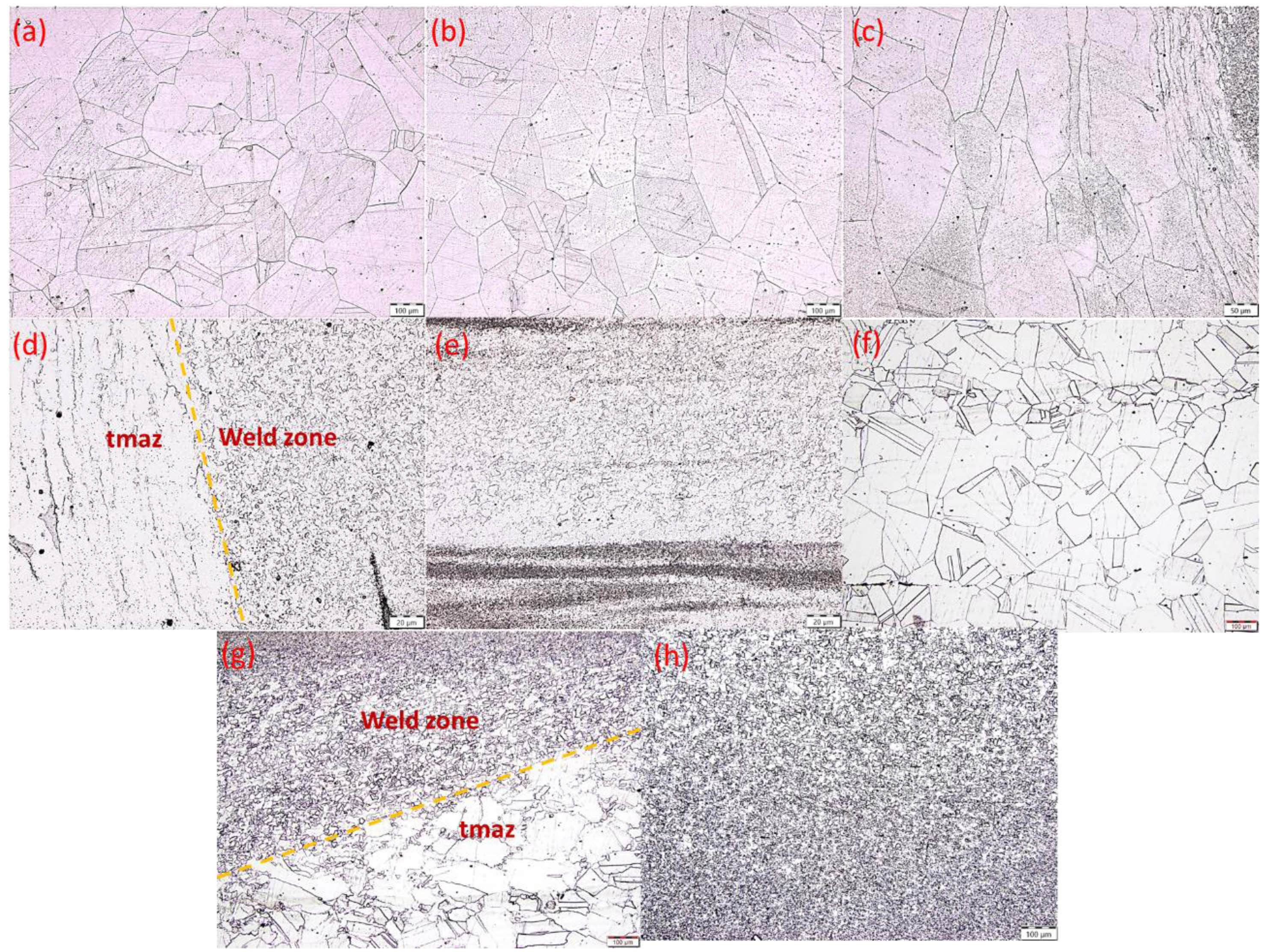
Fig. 3a displayed the microstructure of the base metal, revealing a structure of large grains. An investigation of the heat-affected zone (HAZ) revealed that it underwent thermal cycles without experiencing plastic deformation. Notably, the initial grain size and precipitate morphology remained largely unchanged within the zone (Fig. 3b). In Fig. 3c, elongated grains in the Thermo-Mechanically Affected Zone (TMAZ) were observed, resulting from material flow induced by the rotating pin, which imparted significant plastic deformation. However, recrystallization did not occur due to insufficient deformation strain. Moving to the nugget zone in Fig. 3e, very fine equiaxed grains were noticed, a result of the dynamic recrystallization process during Friction Stir Welding (FSW). The combination of temperature rises and severe plastic deformation contributed to grain size reduction. It's essential to note that the microstructural changes in the Stir Zone (SZ) and TMAZ differed due to the influence of both heat and friction forces, leading to distinct grain refinement patterns. These areas could be categorized into three structural types. Firstly, in the SZ, fine-grained regions underwent recrystallization, resulting in significantly smaller grain sizes compared to other regions. This was primarily because the tool pin came into direct contact with the SZ and stirred it until it assumed a smaller, fractured shape. Secondly, coarse-grained areas existed in the TMAZ, featuring larger grains than the SZ. This difference arose from the fact that the TMAZ primarily received heat, unlike the SZ, which experienced both heat and friction forces, as illustrated in Fig. 3d. Finally, equiaxed grain regions in the thermal-mechanical affected zone were influenced by both heat and some friction force, resulting in plastic deformation. In the stir zone, grain refinement was achieved through dynamic recrystallization (DRX), which occurs due to significant deformation and temperature input during friction stir welding [31]. The plastic flow of the material into the stirred area led to increased strain rates and stored energy, while the tool and material generated frictional heat. The material used in this study had lower stacking fault energy, making it more susceptible to DRX compared to materials with strong stacking fault force. Materials with lower stacking fault energies are more likely to organize into recrystallization nuclei, promoting the development of dense recrystallization nuclei during friction stir welding [32].
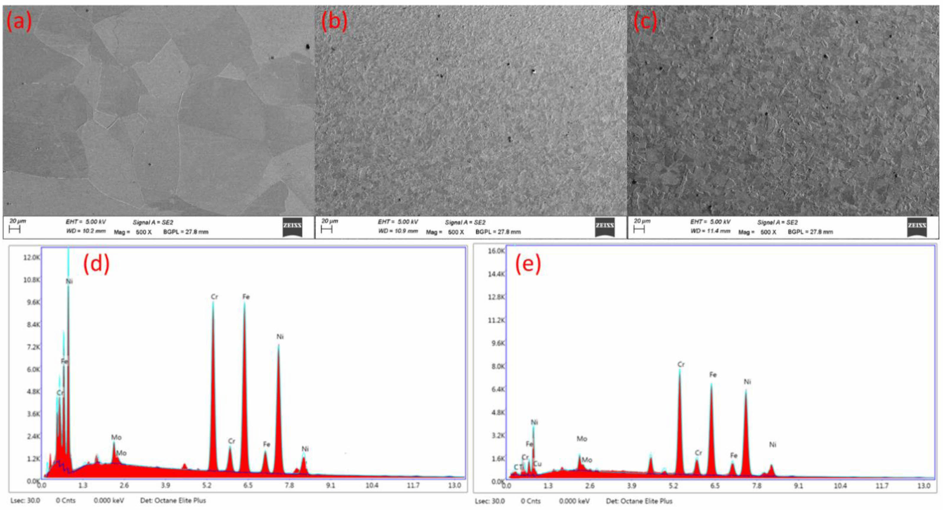
In the Friction Stir Welding (FSW) of carbon nanotube (CNT)-reinforced Incoloy 825 sheets, several microstructural features were observed using scanning electron microscopy (SEM) and energy-dispersive X-ray spectroscopy (EDAX) analysis (Fig. 4). The SEM images of the base metal revealed a typical microstructure of Incoloy 825, with equiaxed grains and a homogeneous distribution of the CNTs. The EDAX data confirmed the presence of the main elements of Incoloy 825: nickel, iron, chromium, and molybdenum. Furthermore, the EDAX data indicated that the stir zone had a similar elemental composition to the base metal. The CNTs were found to be well-dispersed within the SZ, with no clustering observed. Although CNTs were nanoscale materials and not directly visible under conventional SEM imaging, the EDX analysis confirmed their presence by detecting carbon signals in the stir zone. This observation suggests that the CNTs were effectively distributed throughout the SZ during the FSW process. In terms of microstructure, the distribution, alignment, and size of the CNTs within the matrix can influence the microstructure of the welded joint. The CNTs can act as nucleation sites for recrystallization and grain growth, which can affect the grain size and shape of the welded joint. The alignment of the CNTs can also affect the mechanical properties of the welded joint. Overall, the SEM images and EDAX data revealed valuable insight into the microstructure of the CNT reinforced Incoloy 825 sheets after FSW. The well-dispersed CNTs within the stir zone suggest that the CNT reinforcement was effectively incorporated into the Incoloy 825 matrix during the FSW process.
X-ray diffraction analysis
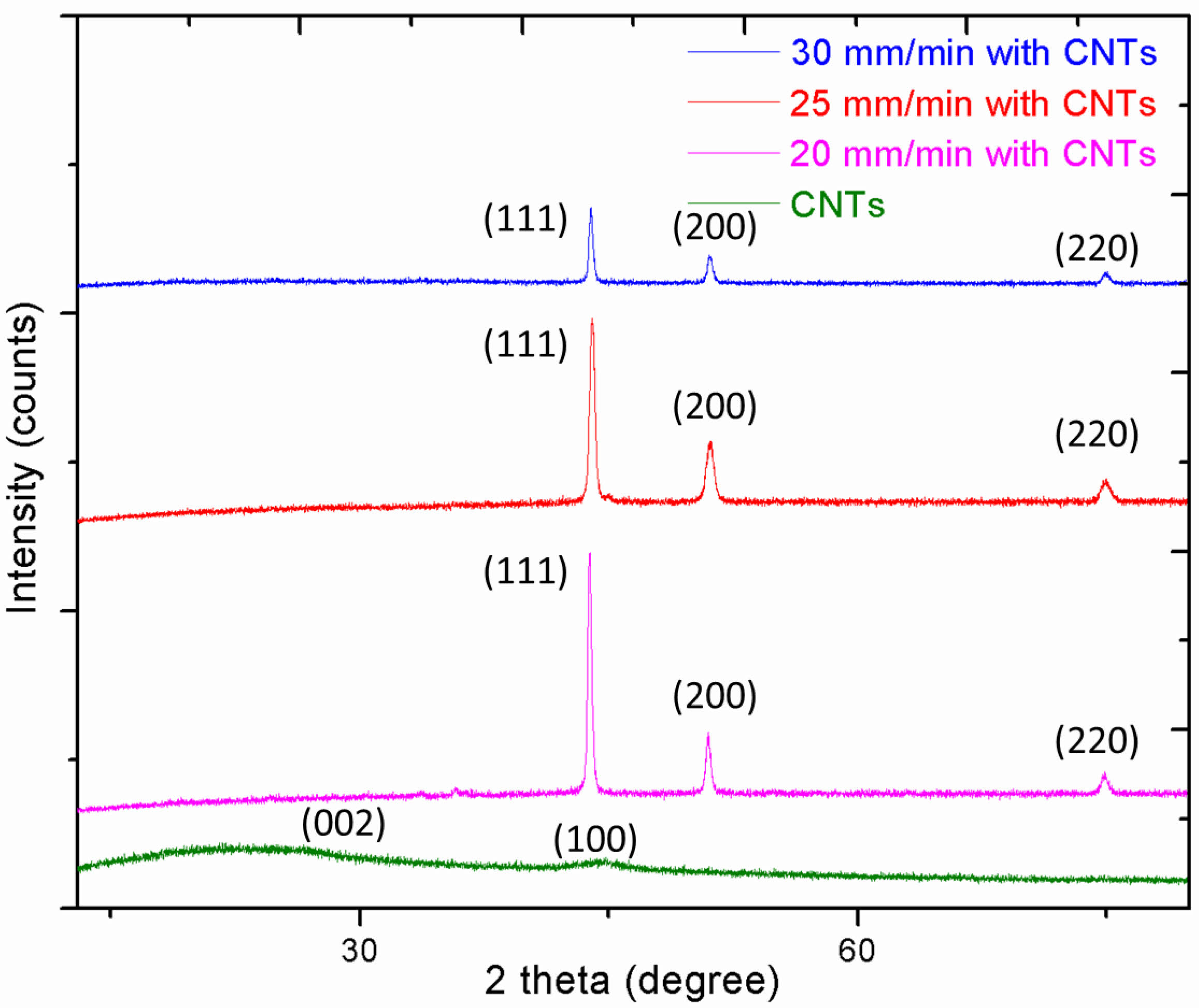
X-ray diffraction analysis was performed on the stir zone of CNT-reinforced Incoloy 825 that underwent friction stir welding (FSW). The X-ray diffractogram displayed in Fig. 5. showed the diffraction peaks from the (111), (200), and (220) planes, corresponding to the crystal structure of Incoloy 825. These diffraction peaks were observed in the stir zone, located 0.5 mm from the centre of the stir region on both the advancing and retreating sides of the cross-section. The absence of additional peaks in the X-ray diffractogram suggests that no significant phase transformation or new phases occurred during the FSW process. This was an important observation, as any changes in the phase or oxidation state of the material could have affected its mechanical properties. Therefore, the X-ray diffraction analysis confirmed that the FSW process did not cause any undesirable changes to the material, which was essential for ensuring the reliability and durability of the welded component. Although XRD analysis is useful for identifying crystalline structures, it may not entirely establish the lack of new phases since it can miss amorphous phases or minor microstructural changes. To overcome this barrier, we used complementary Raman spectroscopy. The Raman spectra confirmed the presence of CNTs by typical peaks while revealing no major structural changes in the Incoloy 825 matrix. The combination of these two analytical approaches strengthens our findings and gives a more complete evaluation of the material's phase stability during the FSW procedure.
Raman spectroscopy analysis
Raman spectroscopy proved to be a powerful analytical technique used to investigate the microstructure and chemical composition of materials, especially those with carbon contain materials. The technique is based on the inelastic scattering of monochromatic light, which results in a shift in the wavelength of the scattered light. This shift is specific to the chemical bonding and crystal structure of the analysed material and can provide valuable information about the chemical composition, crystalline structure, and morphology of the CNTs in the material. The penetration depth of Raman spectroscopy in friction stir welding (FSW) joints is an important component in the identification and characterization of CNTs in the stir zone.
The penetration depth is mainly affected by the laser wavelength, the optical characteristics of the material, and the sample's surface condition. In general, shorter laser wavelengths exhibit lower penetration depths, typically ranging from 10 nm to 500 nm, while longer wavelengths can penetrate up to a few micrometres. In the context of FSW joints, the metal matrix, often composed of nickel alloys, has high reflectivity and absorption, which further limits the laser's effective penetration depth. As a result, Raman analysis in these regions is typically confined to the near-surface layer, and detecting CNTs dispersed deeper within the stir zone can be challenging. The Raman signal is also influenced by the stir zone's heterogeneous microstructure, which is the product of extreme plastic deformation and dynamic recrystallization. Surface roughness can scatter the incoming laser, lowering the effective penetration depth and signal intensity of deeper-embedded CNTs. Thus, CNTs situated outside the laser's penetration range may not be detectable by traditional Raman spectroscopy.
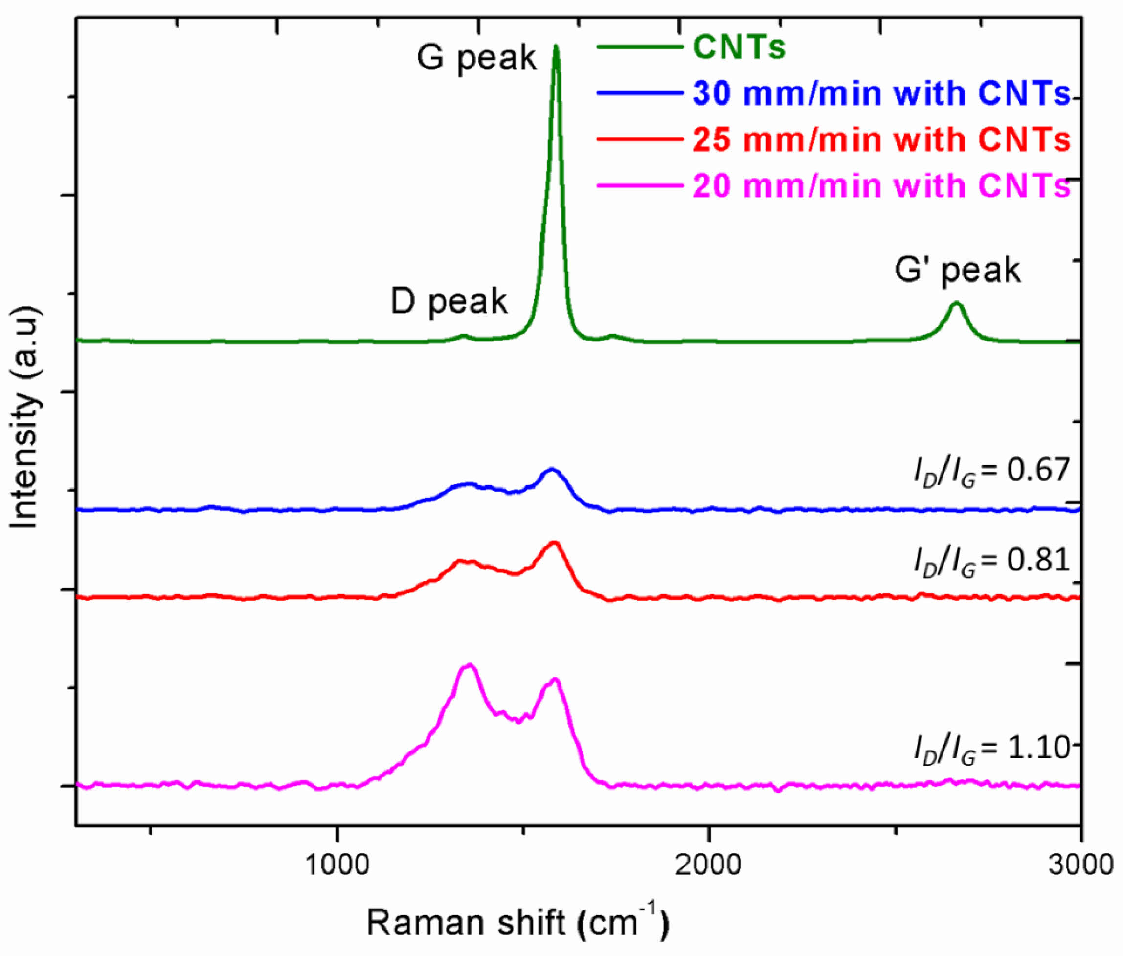
In the FSW of Incoloy 825 sheets reinforced with CNTs, Raman spectroscopy was employed to identify the presence of CNTs in the stir zone and confirm their dispersion within the matrix material (Fig. 6). Typically, Raman spectra of CNTs exhibit a strong peak at around 1580 cm-1 (G band), corresponding to the radial breathing mode (RBM) of the CNTs, and a peak at around 1350 cm-1 (D band), corresponding to the tangential mode (TM) of the CNTs [33]. The presence of these two bands indicates the presence of CNTs in the composites. The intensity and shape of these peaks, particularly the D band, can provide insights into the structural defects and crystallite size of the CNTs. The R-value is a crucial parameter in Raman spectroscopy, a technique used to analyse the vibrational modes of materials. In simple terms, it is the ratio of the D peak intensity to the G peak intensity, providing insight into the disordered carbonaceous components present in the material [34]. The results showed that the R-value of the FSW of Incoloy 825 sheets reinforced with CNTs was 0.67 at a speed of 30 mm/min. This value indicated that the disordered carbonaceous component was slightly lower than the values recorded at speeds of 20 mm/min and 25 mm/min. Thermo-mechanical stresses during the FSW process could lead to the appearance of structural defects in the CNTs, resulting in broadening and shortening of the peaks. Additionally, amorphous carbons may have segregated the CNT clusters due to severe shear stresses, resulting in shortened CNTs, potential formation of free carbons and other carbon products. In some cases, nanotube shortening might also have resulted in carbide formation. The combination of XRD and Raman spectroscopy enabled a thorough knowledge of the phase stability and microstructural integrity of CNT-reinforced Incoloy 825 joints during FSW. This comprehensive analytical method demonstrated that the FSW technique maintained the structural integrity of both the Incoloy 825 matrix and the included CNTs, assuring the mechanical dependability of the welded connections.
Tensile properties and hardness
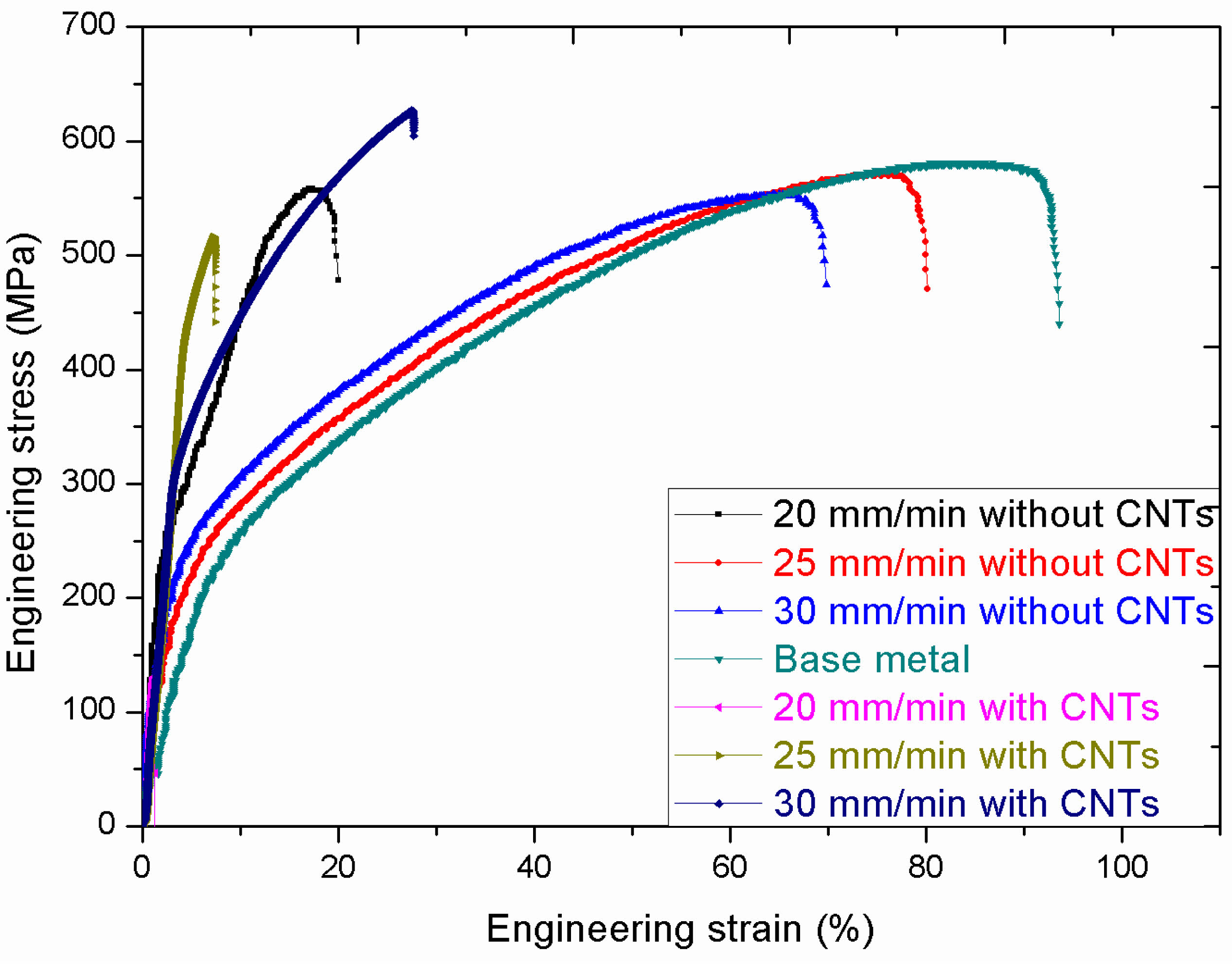
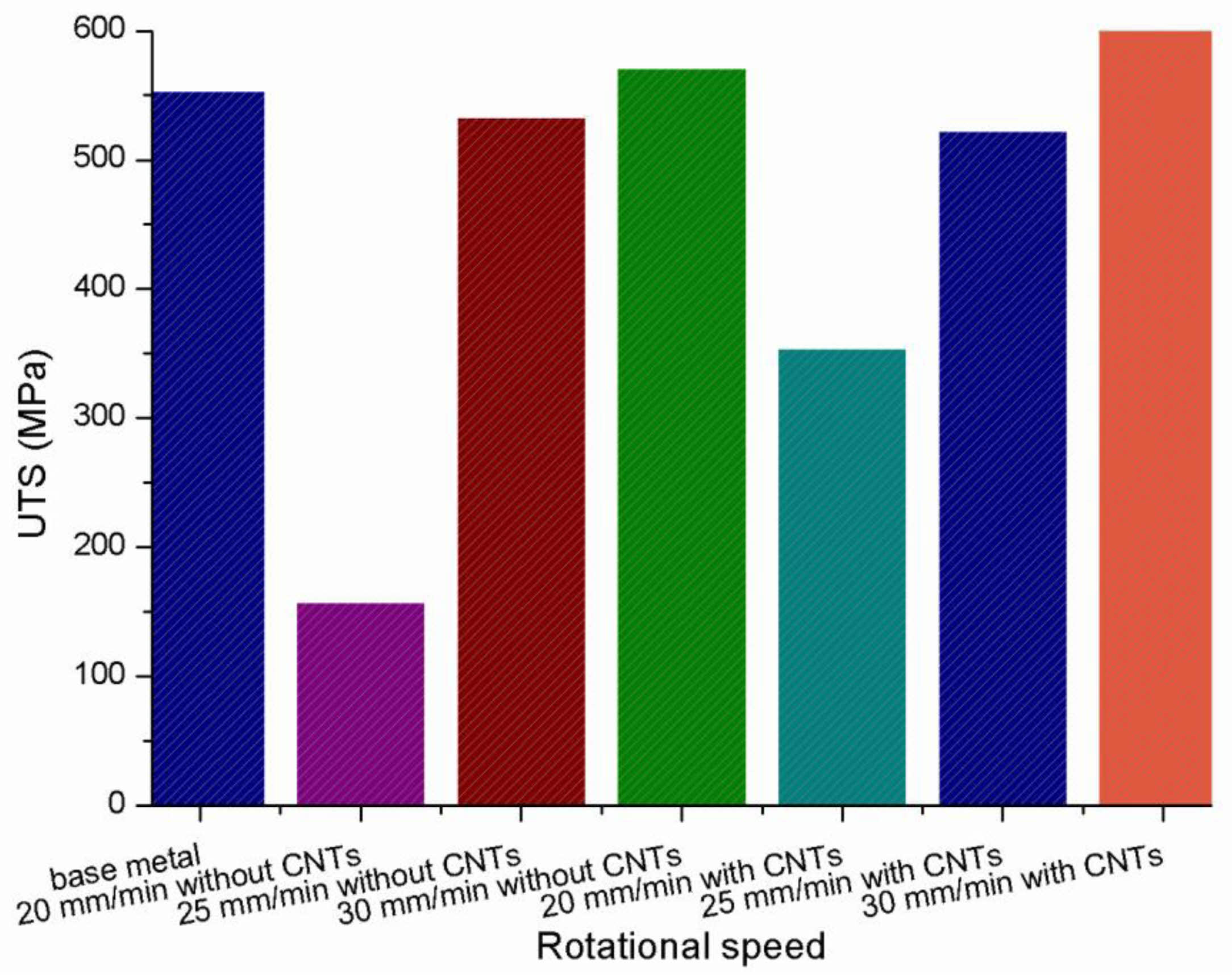
The mechanical properties of carbon nanotubes (CNTs) reinforced friction stir welded (FSW) Incoloy 825 alloy joints were investigated. Tensile tests were conducted at room temperature with various welding speeds (20 mm/min, 25 mm/min, 30 mm/min), tool rotation speed of 400 rpm, with and without CNTs. The engineering stress-strain curve of the welded joints, tensile properties were shown in Fig. 7.andFig. 8.The results showed that the CNT reinforced FSW Incoloy 825 alloy joints exhibited higher tensile strength compared to the base metal and FSW of Incoloy 825. The maximum tensile strength was obtained with a welding speed of 30 mm/min (571 MPa), which was 2.5% lower than the parent material. However, with the addition of CNTs, the tensile strength of the welded joints was reduced at 20 mm/min welding speed (354 MPa), but increased at 25 mm/min (522 MPa) and 30 mm/min (615 MPa) welding speeds. The tensile test results reveal considerable variability in tensile strength across different welding speeds. Tensile strength was lowered at lower welding speed (20 mm/min) due to inadequate material mixing and CNT dispersion. However, at an optimal welding speed of 30 mm/min, tensile strength increased significantly, due to improved CNT dispersion and excellent grain refinement in the stir zone. The strengthening processes are principally influenced by CNT-induced load transfer, grain boundary strengthening, and dislocation pinning effects. These findings suggest that properly controlling welding environments are able to have a considerable impact on mechanical performance in CNT-reinforced FSW joints.
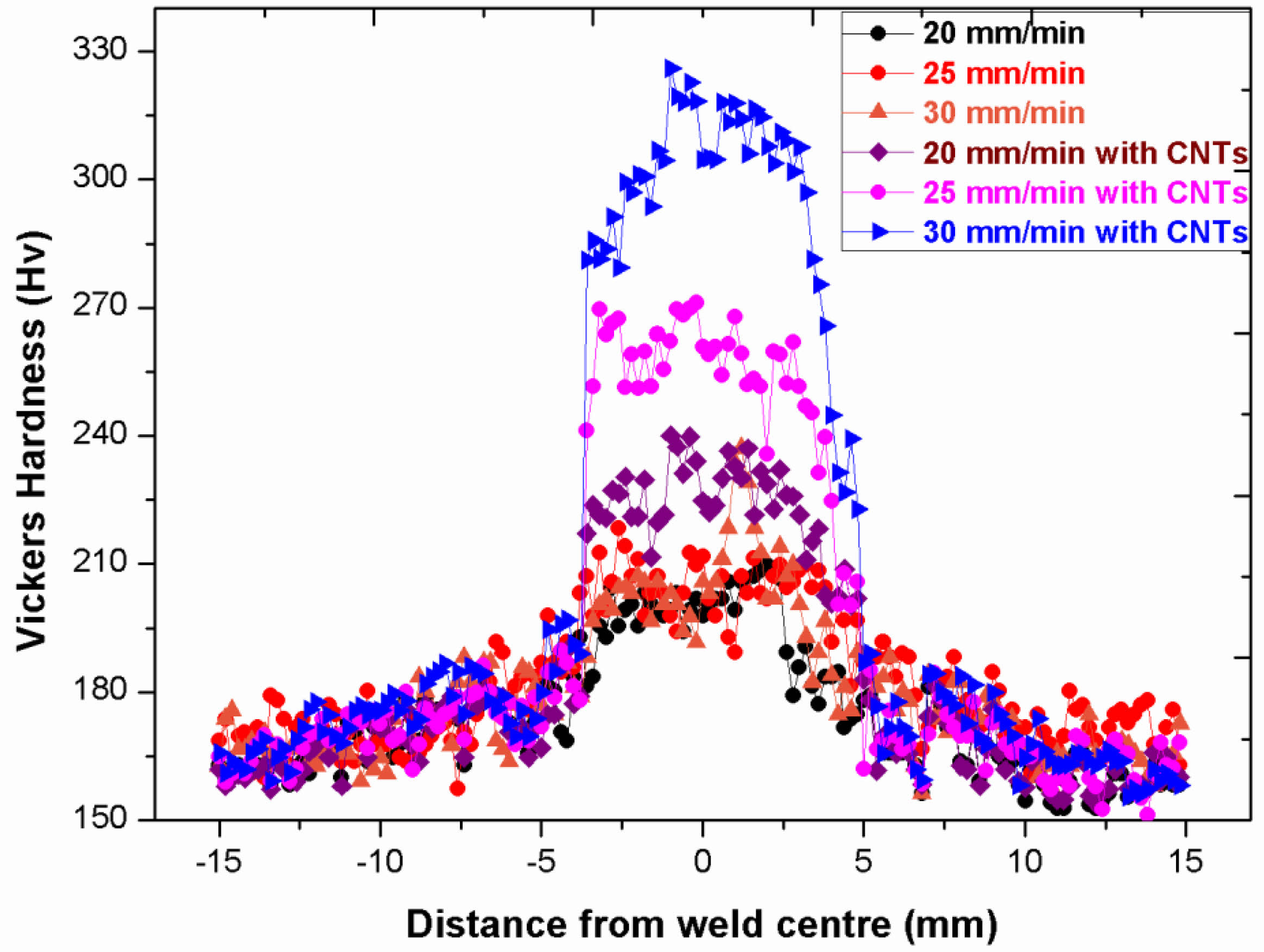
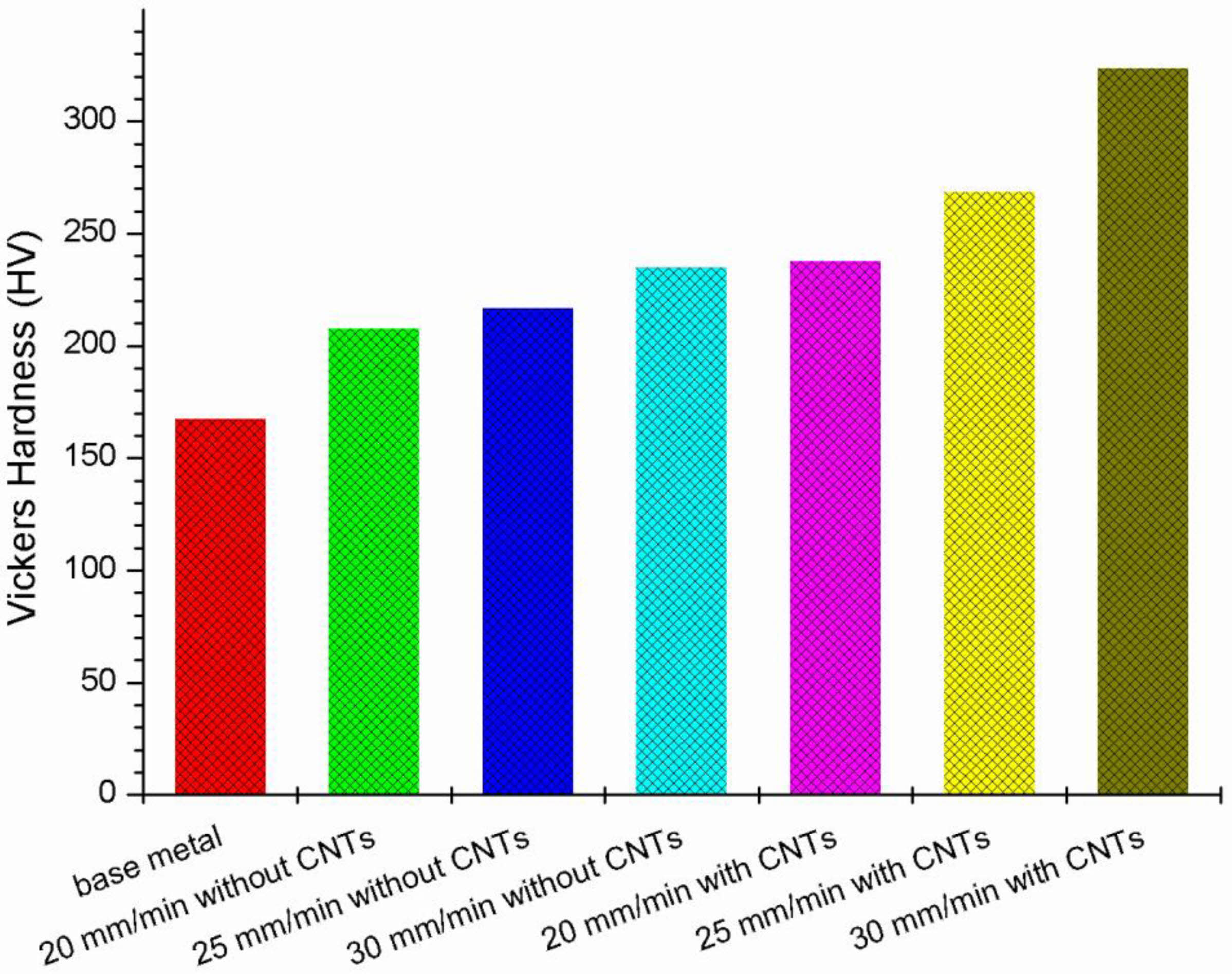
The Vickers micro-hardness profiles were examined for both FSW and CNTs reinforced FSW systems, with results plotted in Fig. 9.andFig. 10. The annealed Incoloy 825 alloy displayed a mean indentation hardness of approximately 168 HV, while this value increased to around 235 HV after FSW modification of the alloy without CNT incorporation. This improvement could be attributed to a slight degree of grain refinement within the SZ after FSW modification without CNTs. The indentation hardness of the SZ increased continuously in both systems, i.e., Incoloy 825 alloy FSW and Incoloy 825 alloy-CNTs FSW, with the incorporation of secondary phase reinforcing agents. The low degree of hardness fluctuation for the SZ of all profiles can be attributed to the onion ring flow pattern for dispersion and intermixing of materials. The strengthening effect of CNTs was observed to be greater than that of Incoloy 825 FSW, as evidenced by a higher level of hardness in the SZ considering the hard nature of the CNTs phase and according to the mixture rule. For Incoloy 825-CNTs FSW composite system, the hardness value increased to around 324 HV at 30 mm/min. A lower maximum hardness value approximately 238 HV was attained for the Incoloy 825 FSW system at 20 mm/min. Simultaneous incorporation of CNTs reinforcing agents led to a more considerable enhancement of indentation hardness in the SZ of the Incoloy 825-CNTs hybrid nanocomposite system, up to around 324 HV, due to combining the strengthening contributions. Therefore, a maximum hardness improvement of around 93% could be noted for the Incoloy 825-CNTs FSW compared to the annealed Incoloy 825 alloy. Vickers hardness data illustrates the substantial impact of FSW and CNT reinforcement on the hardness of Incoloy 825, with CNTs playing a crucial role in enhancing the material's mechanical properties. This is attributed to grain structural refinement and the mixture rule, demonstrating the effectiveness of improving the material's hardness and, by extension, its overall mechanical performance.
|
Fig. 3 The microstructure of (a) base material exhibited large grains, representing initial material state; Friction stir welded Incoloy 825 with carbon nanotubes (b) heat-affected zone (HAZ) experienced thermal cycles with unchanged grain size, (c) thermo-mechanically affected zone (TMAZ) had elongated grains from rotating pin, no recrystallization due to insufficient deformation strain, (d) Stir Zone (SZ) and TMAZ differed due to heat and friction, causing distinct grain changes. (e) Nugget zone had fine equiaxed grains due to dynamic recrystallization from elevated temperature and severe plastic deformation during welding; Friction stir welded Incoloy 825 without carbon nanotubes (f) heat-affected zone (HAZ), (g) Interface between TMAZ-weld zone, and weld zone (h) SZ had remarkable grain refinement through dynamic recrystallization, resulting in much smaller grains. |
|
Fig. 4 SEM micrographs of (a) as received Incoloy 925 base metal (b) stir zone of the Incoloy 825 alloy without CNTs (c) stir zone of the Incoloy 825 alloy with CNTs (d) EDX spectra of FSW Incoloy 825 alloy without CNTs stir zone (e) EDX spectra of FSW Incoloy 825 alloy with CNTs stir zone. SEM and EDAX analyses revealed that the CNTs were well-dispersed within the stir zone (SZ), and no clustering was observed. This suggests effective distribution and alignment of the CNTs throughout the SZ during FSW. |
|
Fig. 5 X-ray diffraction spectrum of as-received CNTs, friction stir welded Incoloy 825 with CNTs at 20 mm/min, 25 mm/min, and 30 mm/min traverse speed. The X-ray analysis confirmed material stability during FSW, ensuring mechanical reliability and durability. |
|
Fig. 6 Raman spectrum of as-received CNTs, friction stir welded Incoloy 825 with CNTs at 20 mm/min, 25 mm/min, and 30 mm/min traverse speed with D, G, G' bands graphene showed at 1350 cm-1, 1580 cm-1 and 2695 cm-1 correspondingly. Raman spectroscopy confirmed CNT presence, providing data on structural characteristics. An R-value of 0.67 indicated lowered disordered carbon content. Some structural defects observed due to thermo-mechanical stresses. |
|
Fig. 7 Engineering stress-strain curve of specimens milled in SZ of with and without CNTs FSW Incoloy 825 alloy at the welding speeds 20, 25, 30 mm/min, base metal. |
|
Fig. 8 Tensile properties of base metal, with and without CNTs FSW Incoloy 825 alloy at welding speeds of 20, 25, and 30 mm/min. |
|
Fig. 9 Distribution of Vickers hardness calculated during the midpoint perpendicular to the welding direction of with and without CNTs FSW Incoloy 825 alloy at welding speeds of 20, 25, and 30 mm/min. |
|
Fig. 10 Average microhardness values of the base metal, with and without CNTs FSW Incoloy 825 alloy at welding speeds of 20, 25, and 30 mm/min. |
The findings of this research suggest that friction stir welding is a suitable method for joining Incoloy 825 joints reinforced with carbon nanotubes. The results demonstrate that the addition of CNTs results in a more homogeneous distribution of nanoparticles with no surface defects in the weld zone. Microstructural analysis reveals that carbon nanotubes reinforced samples exhibit a fine recrystallized grain structure in the processed nugget due to the concurrent reaction of severe plastic deformation and friction heating during the FSW process. Incoloy 825-CNTs FSW samples exhibit higher microhardness distribution of 324 HV in the processed nugget zone, attributed to the uniform distribution of CNTs within Incoloy 825 and the Hall-Petch relationship that results in a fine grain morphology in the weld zone. A maximum hardness improvement of around 93% was observed for the Incoloy 825-CNTs FSW compared to the annealed Incoloy 825 alloy. Furthermore, the ultimate tensile strength of the Incoloy 825 sample reinforced with CNTs showed a significant improvement compared to the unreinforced sample, with an 5% increase compared to the parent metal. This enhancement is credited to the high density of CNTs that provides more nucleation sites, which restricts the path of grain boundaries. Overall, this research demonstrates that the addition of CNTs can significantly enhance the mechanical properties of Incoloy 825 alloy FSW welds, resulting in improved microhardness and tensile strength. The fine recrystallized structure of grains in the processed nugget and the uniform distribution of CNTs contribute to the superior mechanical properties of the reinforced welds.
The authors would like to thank the authorities of Koneru Lakshmaiah Education Foundation, Guntur, for providing facilities to carry out this work. The authors are also thankful to the Sophisticated analytical instrument facility (SAIF), Mahatma Gandhi University, Kottayam, for the Raman spectroscopy facility and Central Analytical Laboratory, BITS Hyderabad, for the powder X-ray diffraction facility.
The authors received no specific funding for this work
The authors confirm that the data supporting the fundings of this study are available within the article.
Not applicable
This research follows all ethical standards.
All authors have agreed with the participation in the presented study.
The authors gave consent for this publication.
The authors declare no competing interests.
- 1. G. Çam, Int. Mater. Rev. 56[1] (2011) 1-48.
-

- 2. R. Girimurugan, J. Bensamraj, and S. Karthick, J. Ceram. Process. Res. 23[4] (2022) 553-557.
-
- 3. P. Gopi Krishnan, B. Suresh Babu, and K. Siva, J. Ceram. Process. Res. 21[2] (2020) 157-163.
-
- 4. W.C. Ke, J.P. Oliveira, S.S. Ao, F.B. Teshome, L. Chen, B. Peng, and Z. Zeng, J. Mater. Res. Technol. 17 (2022) 1942-1954.
-
- 5. R. Srinivasan, B. Suresh Babu, P. Prathap, R. Whenish, R. Soundararajan, and G. Chandramohan, J. Ceram. Process. Res. 22[1] (2021) 16-24.
-
- 6. K. Rajesh Kumar, D. Kiran Kumar, and V. Venkata Satyanarayana, J. Ceram. Process. Res. 24[3] (2023) 439-445.
-
- 7. N. Kumar and V.K. Patel, SN Appl. Sci. 2[9] (2020) 1572.
-
- 8. Z. Ma, X. Sun, S. Ji, W. Yue, and Y. Yumei, Int. J. Adv. Manuf. Technol. 112 (2021) 2573-2582.
-
- 9. S. Gurgen, in “Advances in Manufacturing for Aerospace Alloys.” (Springer, Cham. 2024). p. 99-115.
-
- 10. P.K. Sahu, S. Pal, and Q. Shi, SN Appl. Sci. 1[12] (2019) 1659.
-
- 11. T.S. Senthil, S.R. Babu, and M. Puviyarasan, Sci. Rep. 13[1] (2023) 5321-5334.
-
- 12. S. Srikanth, A. Parthiban, M. Ravikumar, and K. Vignesh, J. Ceram. Process. Res. 23[4] (2022) 523-528.
-
- 13. K. Jalal and S. Morteza, J. Manuf. Process. 26 (2017) 407-418.
-
- 14. A. Halil and A. Yelda, Mater. Des. 50 (2013) 515-521.
-
- 15. J. Kangazian, N. Sayyar, and M. Shamanian, Metallogr. Microstruct. Anal. 6[3] (2017) 190-199.
-
- 16. S. Liu, J. Huang, J. Zhang, X. Yu, and D. Fan, J. Mater. Eng. Perform. 30[5] (2021) 3735-3748.
-
- 17. K.H. Song and K. Nakata, Mater. Trans. 50[10] (2009) 2498-2501.
-
- 18. G.V.B. Lemos, A.B. Farina, R.M. Nunes, P.H.C.P. Cunha, L. Bergmann, J.F. Santos, and A. Reguly, J. Mater. Res. Technol. 8[3] (2019) 2528-2537.
-
- 19. K.H. Song and K. Nakata, J. Alloys Compd. 505[1] (2010) 144-150.
-
- 20. J. Kangazian and M. Shamanian, Trans. Nonferrous Met. Soc. China 29[8] (2019) 1677-1688.
-
- 21. P. Varalakshmi, B.S. Sudhakar, and K.B. Vijaya, J. Ceram. Process. Res. 24[2] (2023) 250-256.
-
- 22. A.A. Al-allaq, J.S. Kashan, M.T. El-Wakad, and A.M. Soliman, J. Ceram. Process. Res. 22[4] (2021) 446-454.
-
- 23. İ. Topcu, M. Ceylan, and E.B. Yilmaz, J. Ceram. Process. Res. 21[5] (2020) 596-601.
-
- 24. S. Mazumder, J.G. Park, N. Sarkar, K.S. Lee, B. Basnet, and I.J. Kim, J. Ceram. Process. Res. 17[12] (2016) 1274-1278.
-
- 25. M. Ceylan and İ. Topcu, J. Ceram. Process. Res. 21[5] (2020) 539-546.
-
- 26. M. Whitby and N. Quirke, Nat. Nanotechnol. 2 (2007) 87-94.
-
- 27. Z. Qi, H.H. Erik, J. Zehua, R. Lei, W. Xuan, S.A. Rolf, L. Andreas, and K. Junichiro, Nano Lett. 13[12] (2013) 5991-5996.
-
- 28. L. Seung-Joon, S.S. Eun, Y. Sun, and F. Hidetoshi, Mater. Charact. 145 (2018) 653-663.
- 29. F. Khodabakhshi, A.P. Gerlich, and P. Svec, Mater. Charact. 131 (2017) 359-373.
-
- 30. Z. Ke, L. Zhenyu, X. Bolyu, and M. Zongyi, J. Mater. Sci. Technol. 33[9] (2017) 1004-1008.
-
- 31. Y. Hu, Y. Niu, Y. Zhao, W. Yang, X. Ma, and J. Li, Mater. Sci. Eng. A 848 (2022) 143361.
-
- 32. X. Liu, Y. Sun, T. Nagira, K. Ushioda, and H. Fujii, Acta Metall. Sin. (Engl. Lett.) 33[7] (2020) 1001-1012.
-
- 33. M.S. Dresselhaus, G. Dresselhaus, R. Saito, and A. Jorio, Phys. Rep. 409[2] (2005) 47-99.
-
- 34. H.M. Heise, R. Kuckuk, A. Srivastava, and B.P. Asthana, J. Raman Spectrosc. 40[3] (2009) 344-353.
-
 This Article
-
2025; 26(3): 492-501
Published on Jun 30, 2025
- 10.36410/jcpr.2025.26.3.492
- Received on Mar 31, 2025
- Revised on May 10, 2025
- Accepted on May 26, 2025
Services
- Abstract
introduction
materials and methods
result and discussions
conclusion
- Acknowledgements
- Funding
- Data availability statement
- Code Availability
- Ethical approval
- Consent to participate
- Consent to publish
- Conflict of Interest
- References
- Full Text PDF
Shared
Correspondence to
- Murali Govindarajan
-
Department of Mechanical Engineering, Koneru Lakshmaiah Education Foundation, Guntur Andhra Pradesh, 522502, India
Tel : +91-863-239-9999 Fax: +91-863-238-8999 - E-mail: muralinitt@gmail.com
Clean-Energy Research Institute(CRI), Hanyang University, 222, Wangsimni-ro, Seongdong-gu, Seoul, 04763, Korea
E-mail: jcpr@hanyang.ac.kr