


- Seismic performance of special RC coupling beams with modified diagonally oriented reinforcement
Young Soo Chun*
Department of Civil Eng., Land and Housing Institute, Dea-jeon City, Korea
In the Asian region, high-rising apartment buildings constructed in areas with high risk of earthquake and utilized coupled shear wall system as a major lateral force resistance system are required recently to apply special detail to the walls and coupling beams. Coupling beams with a small span-to-depth ratio and high shear stress, in particular, are required to reinforce with two intersecting group of bars symmetrical about the mid-span. In South Korea, however, apartment buildings are constructed using coupling beams with about 200 mm thickness, the same as the wall thickness. In this case, the coupling beams have already complicated bar arrangement and are hardly workable in the field. When applied in connection with walls with special detail, bar arrangement is too complicated especially in the joint between the coupling beams and walls to be constructed in the field. To solve such a problem, this study reports the seismic performance evaluation results of a new type of reinforcement detail (DSB detail) that replaces the reinforcement with two intersecting groups of diagonally placed bars symmetrical about the mid-span with single diagonally oriented reinforcement and substitutes tie force for some part of the force upon the diagonally oriented bundle-formed reinforcements. As a test result, the specimens with DSB details were found to have a similar deformation capacity, energy dissipation capacity and low strength reduction and stiffness reduction, compared with the diagonally bundle-formed reinforcement. DSB stirrups and ties are deemed to be a practical alternative to replace the hoop of diagonally bundle-formed reinforcement, which is to constraint concrete in coupling beams.
Keywords: Coupling beams, Seismic resistance, Modified diagonally Oriented reinforcement
Recently, among the apartment buildings constructed in the Asian region, demand for high-rise apartment buildings with at least 20 stories is increasing. Similar to most other high-rising buildings of reinforced concrete, such apartment buildings also adopt the coupled shear wall system as a major lateral force resistance system. When the coupled shear walls are utilized as earthquake force resistance system, the KBC2016 (2016) of South Korea code to apply special details to the walls and coupling beams of structures as high as 60m or over in the seismic design category of D. Such a set of regulation is also found in the US ASCE/SEI7-10 (2010). It regulates to use the reinforcement with two intersecting groups of diagonally placed bars symmetrical about the midspan (hereinafter, the GDR detail) to beams with a low span-to-depth ratio and high shearing stress. Such a situation as described above indicates that there are many cases requiring the use of walls and coupling beams with special details in designing high-rise apartment buildings. Many South Korean apartment buildings are constructed in wall-slab structure using coupling beams in a similar thickness to walls at around 200 mm, and there are lots of difficulties in terms of their constructability and economy because coupling beams have too complicated details such as the GDR detail. Therefore, alternative detail development is increasingly demanded to help improve the constructability.
In the coupled shear wall system, coupling beams become easily plastified and, depending upon the coupling bean details, seismic performance of wall can vary. Therefore, coupling beam details have been mainly experimented in studies. The GDR detail was suggested based on the studies by Park & Paulay in the 1970s. The method was proposed as a way to improve the seismic performance of beams with a low span-to-depth ratio and high shearing stress. However, according to the recent study by Naish et al.(2009), lateral constraint of the entire beams was found to have better performance results in strength and deformation capacity than those of the existing GDR detail. In reflection of this finding, recent US standard (ACI318-14, 2014) suggests using the lateral constraint of the entire beams in addition to the existing diagonally bundle-formed reinforcement details. However, in the case of using narrow-width coupling beams around 200mm, not any sufficient set of details has yet to be completed.
Therefore, this study propose a method to improve constructability by using large-size single rebar as an alternative detail to the diagonally oriented bundle-formed reinforcement (hereinafter, the DSB detail). The DSB detail replaces bundle-formed diagonal reinforcement with one or two single diagonal reinforcement with an equivalent cross-section area; and uses stirrups and ties to apply lateral constraint to the whole beams in order to make the diagonal reinforcements and lateral constraint reinforcements share the shear stress at a certain rate and improve the constructability. This paper presents the comparison of DSB seismic performance with that of the GDR detail, based on experimental results of coupling beams with the span-to-depth ratio not higher than 2.0, which requires diagonal reinforcement.
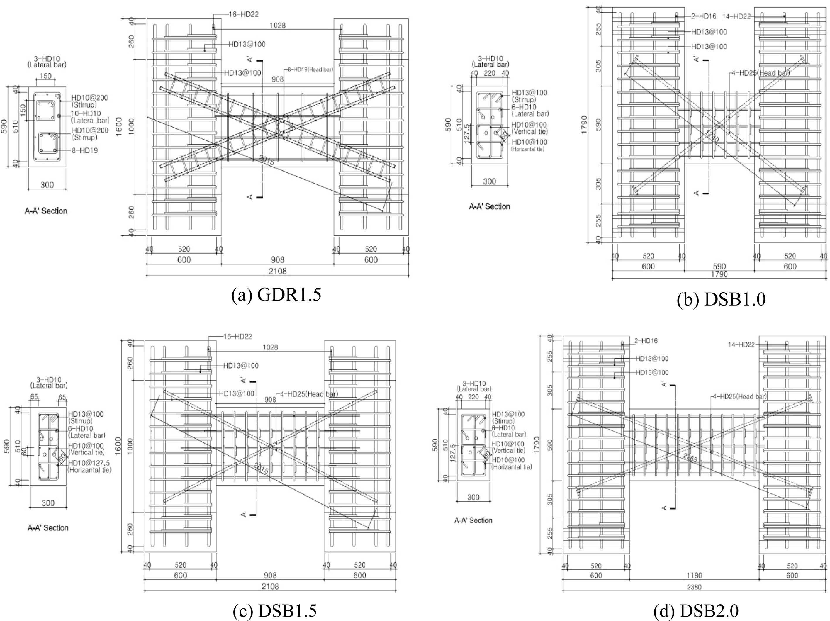
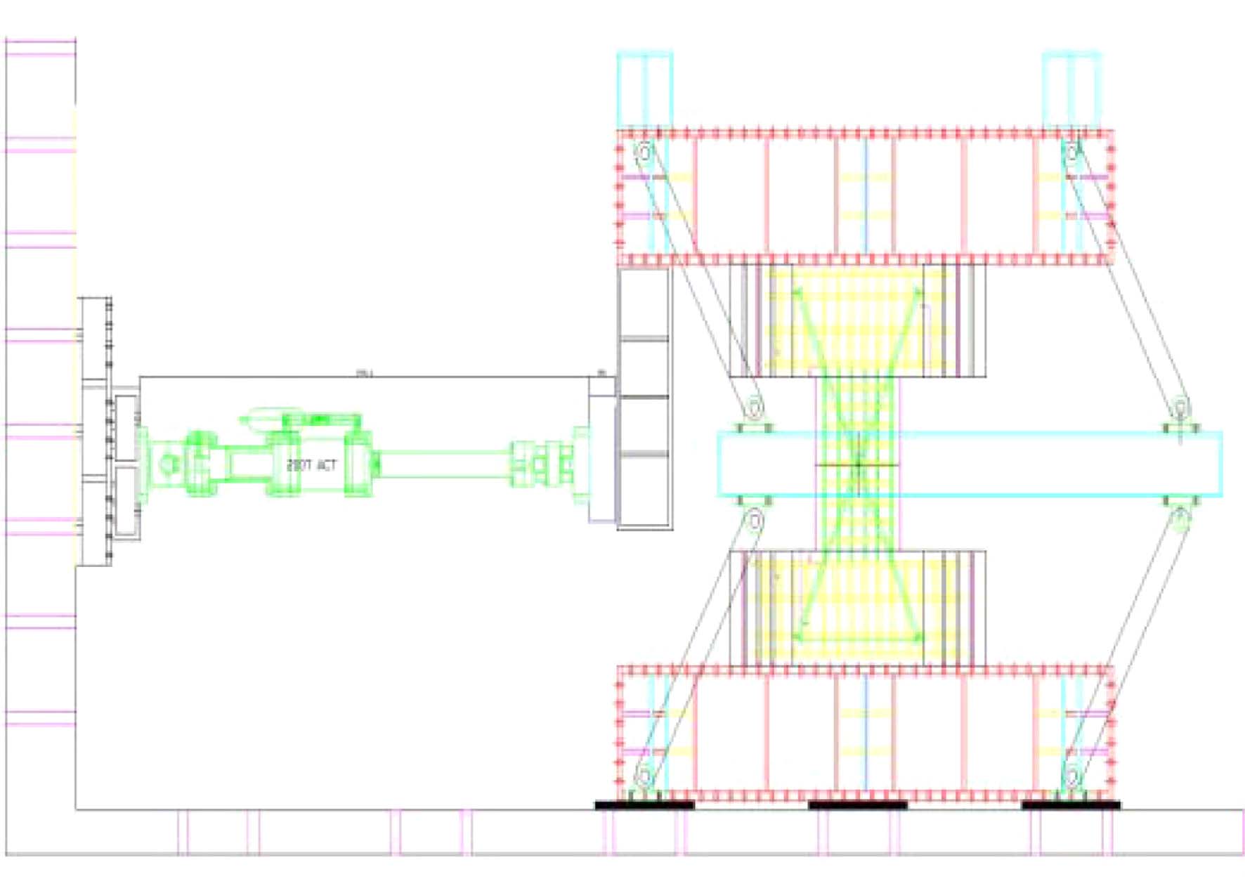
Table 1 and Fig. 1 show information of test specimens and bar arrangement details. Test variables are shear reinforcement detail and span-to-depth ratio in 4 specimens in total. An experimental comparative reference was set as GDR detail specimen and 1.5 span-to-depth ratio was set as a representative variable in the experimental range. The coupling beam and both end walls were modeled for the specimen form. Specimens were produced in full-scale. Table 2 shows the material test results of the concrete and rebar used in this experiment. H-formed specimens were installed by rotating 90 degrees as in Fig. 2 to ensure easy application of force. Link joint was used to apply force horizontally upon the steel connected to the upper-part wall in the middle of beam span to make double curvature. Also, to prevent coupling beam buckling outside the plane, ball zigs were installed on the left and right sides of upper-part steel frame. Force upon the specimens was applied incrementally in the displacement control method on the basis of the deformation angle. Force was applied three times for each cycle. Fig. 3 shows the displacement history under force application.
1) Reinforced with two intersecting groups of diagonally placed bars symmetrical about the midspan
2) Reinforced by diagonal bars and constraining the entire beams laterally with, stirrups and ties (Shear force sharing ratio of ties: 15%)
3) =500MPa (not higher than D13), 600MPa (more than D16)
|
Fig. 1 Bar arrangement details of specimens. |
|
Fig. 2 Specimen installation. |

|
Fig. 3 Loading history. |
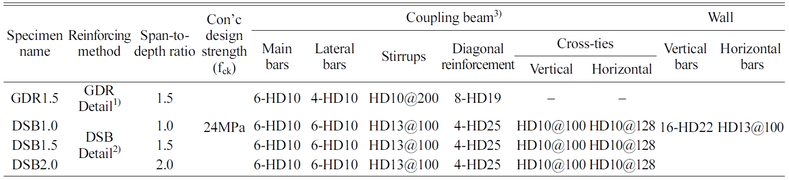
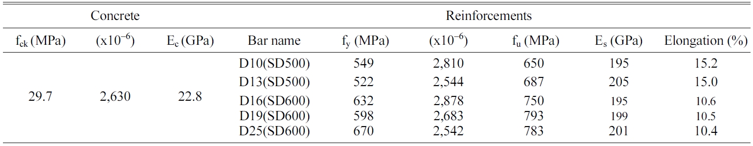
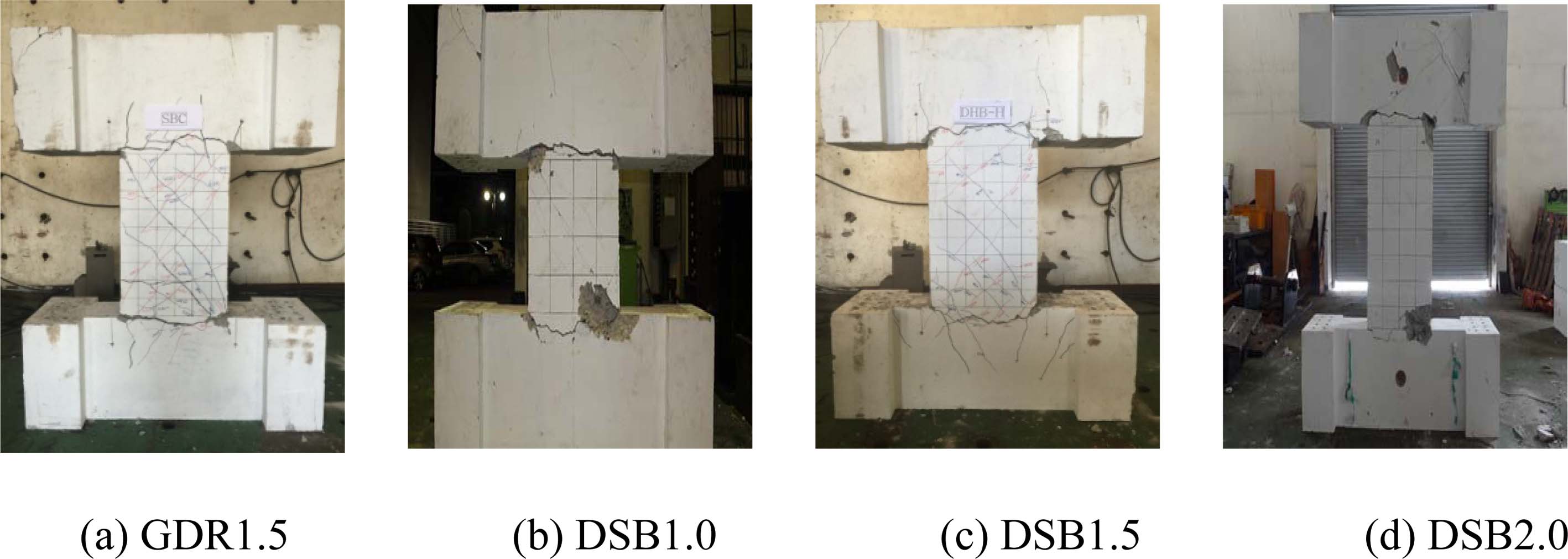
Fig. 4 shows the cracks and final failure patterns of each specimens. Initial cracks started at about 0.2% drift horizontally in the joint area between beam and wall. These cracks were aggravated with the experiment progress and beam diagonal cracks were developed as well. After 1.2% drift ratio, these cracks were far more expanded and serious cracks were developed in beam-wall joint area to undermine the load carrying capacity to be destroyed. All of the specimens showed almost similar failure patterns until the final failure while showing differences just in beam crack distribution degree. Serious diagonally-oriented cracks in beams were not observed, indicating the DSB detail had almost similar level of reinforcement effect with the GDR detail.
|
Fig. 4 Cracks and final failure. |
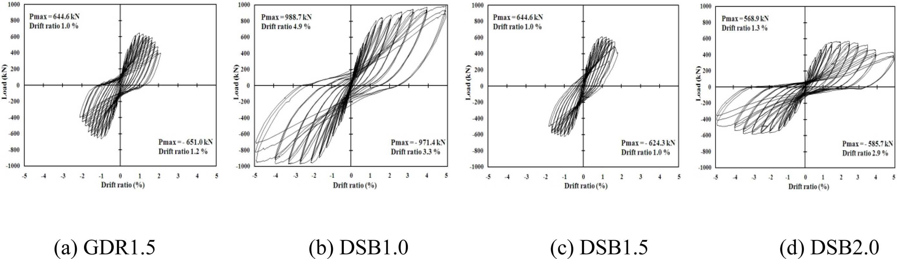
Table 3 shows the experimental results and Fig. 5, the load-drift relationship in the specimens. First, regarding the load-drift relationship, the overall hysteresis responses were found to have no serious pinching effect and almost all of the specimens showed similarly stable behaviors. In the load-drift relationship response, it is noticeable that different the span-to-depth ratios result in different deformation capacity levels, thus, the smaller the span-to-depth ratio, the larger the strength reduction after the load peak. GDR1.5 and DSB1.5 were directly compared with each other. And based on it, it was found that DSB detail and GDR detail showed similar behaviors in terms of load carrying capacity, energy dissipation capacity and deformation capacity.
|
Fig. 5 Load-drift relationship. |
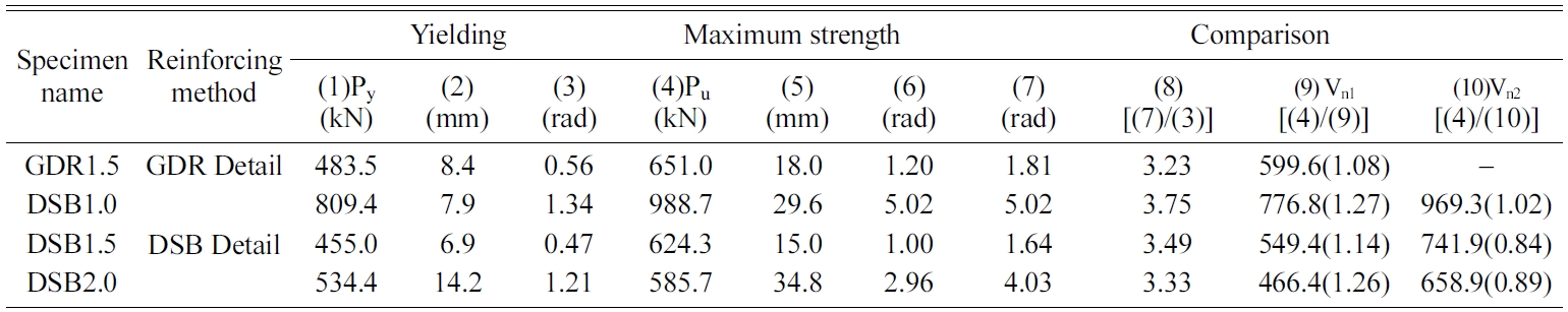
To compare the ductility capacity, the rotation ductility index was used in this study. The rotation ductility index is the ratio of yield rotation angle to max rotation angle. Here, the rotation angle is defined as the ratio of relative displacement at both beam ends to beam net span. The final failure was recognized at the point of 80% of the force after the peak load. For yield load, the bi-linear approximation was applied, which uses reduced stiffness based on 75% of the max strength on the load-drift relationship curve. Table 3 and Fig. 5 show results proving that, despite possible deviation according to the yield load definition, DSB detail can demonstrate almost similar level of deformation ability, compared with the GDR detail.
By comparing the GDR1.5 specimen and DSB1.5 specimen in Table 3, it is noticed that DSB coupling beam has almost shear resistance capacity to that of GDR coupling beam. The average shear stress of the specimens in this study () was 4 MPa ~ 5 MPa. Similar shear resistance capacity was found in a preceding study (Paulay and Binney, 1974) on coupling beams with diagonally oriented bundle-formed reinforcement detail (l/h = 1.3). Therefore, to reduce diagonal reinforcement quantity and burden tie reinforcements with a portion of the shear strength is considered an alternative to the existing diagonally bundle-formed reinforcement. Such a method could help improve the constructability while demonstrating the similar shear resistance to that of GDR detail.
In Table 3, Vn2 is the value produced by calculating each of the shear strength of ties (Vs) and shear strength of diagonal reinforcements (Vd) and overlapping them. As the result of comparison, it was noted that estimated values generally overestimated specimen strengths. This is because more stirrups and ties were used than those necessary for the tie strength of sharing assumed in this study in order to meet the minimum interval requirement of structural standard, etc; and, also because the specimens experienced bending failure earlier than reaching the full shear strength. It seems necessary to consider, in calculating the shearing strength, not only the diagonal reinforcement contribution as suggested in the present code equation, but also the tie contribution together. Since this study has limited experimental results in precisely predicting tie contribution, additional research will be necessary in this regard.
Energy dissipation capacity is an essential measure to assess seismic performance. In the seismic response of coupled shear wall system, a desirable mechanism is to make coupling beams to dissipate energy first through yielding before coupling beam-wall joint dissipates most of the energy. As a result, it was found that, after multiple cracks across the specimens at 0.6% rotation angle with load increase, the accumulated energy dissipation amount increased rapidly. This pattern of energy dissipation was observed as a result of the spread of the plastic hinges near the beam-wall joint region toward the inside of beam. All of the specimens showed similar results. Due to the difference in loading capacity according to different span-to-depth ratios, it is hard to directly compare the energy dissipation capacity of every specimen. But GDR1.5 (14.2 kN·mm) and DSB1.5 (15.2 kN·mm) which have the same span-to-depth ratio showed almost equal energy dissipation amounts. It is able to conform the fact that DSB coupling beam has almost equal energy dissipation capacity to that of GDR coupling beam. This finding is deemed because the stirrup and tie contribution to shear and concrete constraint effect delayed strength and stiffness reduction of specimens while increasing the deformation capacity.
This study evaluated the seismic performance of special RC concrete coupling beams with DSB detail (single diagonal reinforcement + stirrup + tie) proposed as an alternative to the diagonally bundle-formed reinforcement(GDR detail) of coupling beam under the KBC2016 and ACI318-14. As a test result, the DSB specimens were found to have similar performances to GDR specimens in terms of deformation capacity, energy dissipation capacity, low strength reduction and stiffness reduction. The findings indicate that stirrups and ties can be a practical alternative to the hoop of diagonally bundle-formed reinforcement to constraint concrete in coupling beams. The study findings, however, are based on a limited number of specimens and span-to-depth ratio (not higher than l/h = 2.0). Thus, if further experiments is implemented to consider diverse span-to-depth ratios and understand general patterns, more practical set of details will be completed.
- 1. ASCE, in “Minimum Design Loads for Buildings and Other Structures (ASCE/SEI 7-10)” (American Society of Civil Engineers, 2010) p.71-78.
- 2. AIK, in “Korea Building Code (KBC2016)” (Architectural Institute of Korea, 2016) p.1.
- 3. R. Park, T. Paulay, in “Reinforced concrete structures” (John Wiley and Sons, 1975) p.1.
- 4. ACI Committee 318, in “Building Code Requirements for Structural Concrete (ACI318-14) and Commen- tary (ACI318R-14)” (American Concrete Institute, 2014) p.300-302.
- 5. D. Naish, J.W. Wallace, in “Reinforced Concrete Link Beams: Alternative Details for Improved Construction” (University of California, 2009) p.1.
- 6. T. Paulay, J.R. Binney, in “Diagonally reinforced concrete beams for shearwalls, shear in reinforced concrete” (American Concrete Institute, 1974) p.579-598.
 This Article
-
2019; 20(S1): 31-35
Published on Jul 20, 2019
- Received on Dec 9, 2018
- Revised on Jan 11, 2019
- Accepted on Jan 11, 2019
Services
Shared
Correspondence to
- Young Soo Chun
-
Department of Civil Eng., Land and Housing Institute, Dea-jeon City, Korea
- E-mail: cysoo@lh.or.kr
Clean-Energy Research Institute(CRI), Hanyang University, 222, Wangsimni-ro, Seongdong-gu, Seoul, 04763, Korea
E-mail: jcpr@hanyang.ac.kr