


- Finite Element Modeling of Beam with Piezoelectric/Piezomagnetic Sensors under Uniform Temperature
Dhanasekaran Rajagopala,*, A. Kumaravelb, S. Arunprasathb, M. Dinesh Babub and S. Elayarajab
aDepartment of Mechanical Engineering, Adhiyamaan College of Engineering, Hosur, Tamil Nadu – 635 109, India
bDepartment of Mechanical Engineering, K.S. Rangasamy College of Technology, Tiruchengode, Tamil Nadu – 637 215, IndiaThis article is an open access article distributed under the terms of the Creative Commons Attribution Non-Commercial License (http://creativecommons.org/licenses/by-nc/4.0) which permits unrestricted non-commercial use, distribution, and reproduction in any medium, provided the original work is properly cited.
The present study aims to investigate the behaviour of mild steel beams subjected to multi-phase magnetoelectroelastic, piezoelectric, or magnetostrictive patches, taking into account the effects of temperature. A finite element method was employed to analyze the electric and magnetic potential of the structure while considering the coupling effects. The findings of this study could provide valuable insights into the behaviour of such structures under varying temperature conditions and contribute to the development of advanced technologies in the field of material science and engineering. Under homogeneous temperature load, the current formulation shows the ability to anticipate the thermal deformation and sensor behaviour of the piezoelectric/ piezo magnetic, magnetostrictive patches. A distinct variation characterizes the positioning of the sensor layer in the beam, and the upper surface of the layer is plotted with transverse displacement, electric potential, and magnetic potential along its length. A comparative numerical analysis was conducted to assess the behaviour of multiphase magneto-electro-elastic, magnetostrictive, and piezoelectric sensor materials concerning magnetic and electric potential. The investigation has been conducted under various boundary conditions.
Keywords: Magneto-electro-elastic ceramic material, Sensors, Electric potential, Magnetic potential.
Due to the explosive growth in the field of spacecraft in recent years, there has been a greater focus on the use of innovative, contemporary materials to control intelligent or smart structures. The piezoelectric sensors/actuators have been used for various engineering applications like, sensing and vibration control of smart or intelligent structures. It is common knowledge that the majority of engineering issues entail the interaction of the thermal, electrical, and mechanical domains. The governing equations for a thermo piezoelectric medium were initially introduced by Mindlin [1]. These equations take into account the mechanical, electrical, and thermal fields. Sunar and Rao [2] further explored the use of thermos piezoelectricity in the finite element method for integrated sensing and control of intelligent structures. The thermos piezo electricity distributed control system and the piezoelectric bimorph finger are studied using a finite element method based on quasistatic equations of piezoelectricity and thermos piezoelectricity. Heat impacts have an impact on the functionality of distributed sensors and actuators for control systems. It is concluded that the different piezoelectric materials and the operational environment of the system influence the system’s impact [3]. Afterwards, Sunar and Rao studied where thermos piezo electricity actuator patches should be placed for cantilever-beam structures [4, 5]. In a study conducted by Tzou and Ye [6], it was demonstrated that precise control of piezoelectric systems under a steady-state temperature field is achievable. The study sheds light on the potential of piezoelectric systems and their application in various fields such as mechatronics, electronics, and engineering. Nowacki [7] has derived the general theorems of thermos piezoelectricity.
Magnetostrictive materials are used in various engineering applications, acting as both sensors and actuators. These materials involve the interaction between mechanical and magnetic fields, giving rise to phenomena such as coupling between the two fields in magnetostrictive transducers. Researchers [8] have explored the properties of magnetostrictive materials, including induced mechanical stresses and permeability variations. The use of magnetostrictive patches in composite laminates has also been investigated [9], with a focus on actuation and sensing. Other studies [10-13] have examined the dynamic behaviour of magnetostrictive smart materials and the convergence and effectiveness of numerical methods for coupled magneto-electro-elastic (MEE) problems [14, 15]. Recent developments in magnetoelectroelastic materials have expanded their potential uses, including as sensors, actuators, and magnetic field probes [16-22]. Micromechanical modelling has been used to analyse the fully coupled magneto-electro-thermo-elastic behaviour of these materials [23, 24], evaluating their effective properties for different volume fractions of piezo-magnetic reinforcement [25]. Isogeometric analysis is a computational engineering approach that aims to unify the design and analysis phases. The isogeometric analysis uses Computer-Aided Design (CAD) basis functions for numerical analysis, bridging the gap between CAD and Computer-Aided Engineering (CAE). While the finite element method (FEM) is commonly used in CAE, Non-Uniform Rational B-Splines (NURBS) are the typical basis functions in CAD [26]. As a result, most IGA research has focused on NURBS-based formulations, which have shown great potential to improve the accuracy and efficiency of numerical simulations [27] [28]. It is found that the MEE coupling isogeometric analysis method (MIGAM) is a powerful technique for investigating coupled multi-physics problems.
The research conducted on magnetoelectroelastic materials has identified a significant gap in the exploration of their sensory behaviour when exposed to thermal environments. To address this issue, the present study aims to investigate and compare the sensory behaviour of piezoelectric, magnetostrictive, and multiphase magnetoelectroelastic materials. The study also aims to assess how uniform temperature rise affects the placement of sensors and to examine the effects of boundary conditions on electric and magnetic potential.
The results of this study have the potential to provide valuable insights into the sensory behaviour of magnetoelectroelastic materials, especially under thermal conditions. These findings can be instrumental in enhancing our understanding of these materials and their potential applications in various industries. Additionally, the study can aid in identifying the optimal locations to place sensors and boundary conditions that can achieve accurate and reliable measurements. The study can also lead to the development of more advanced and refined materials, which can further support and enhance the applications of magneto electro elastic materials in various fields.
The fundamental equations governing the behaviour of a magneto-electro-thermo-elastic solid [29] are as follows,

Where i, j = 1,....., 6 and l, k = 1,....., 3. Every tensor representation has been represented using the shortened notation, (T1 = Txx, T2 = Tyy, T3 = Tzz, T4 = Tyz, T5 = Txz, and T6 = Txy). Where η, Bl, Ti and Dl are the equivalent modules of entropy, magnetic induction, stress, and electric displacement per unit volume. μlk , εlk , εij, are the coefficients of magnetic, dielectric, and elastic permeability, respectively. mik, eki, dki are the material coefficients for magnetoelectric, piezoelectric, and piezo magnetic materials, respectively. θ and βij are, respectively, the temperature differential and the stress temperature coefficient. Ek, Hk and Sj are the vectors for the electric field, magnetic field, and linear strain tensor, respectively.
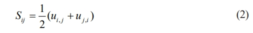
In finite element analysis, three equations are used in addition to the essential equations: electric field-electric potential, strain displacement, and magnetic field-magnetic potential. Eq. (2) can be used to express the strains Sij associated with displacement ui as [29],
The electric potential f and magnetic potential y are used to calculate the electric potential f and magnetic potential y from eq. (3) [29],

Four-node quadrilateral elements are used in the analysis, with each node having d.o.f beingdisplacement in x directionu1, displacement in z direction u3, electric potential Φ and magnetic potential ψ. The shape functions indicated in eq. (4) can be used to represent the mechanical displacements, electric potential, magnetic potential, and temperature [29].

{uie}={u1 u3}T, u1andu3are displacement inx and zdirections respectively. To derive the governing equations at the element level, it is necessary to express {S}, {E}and {H} the degrees of freedom and the derivatives of shape functions using equations (2) and (3) as follows [29],

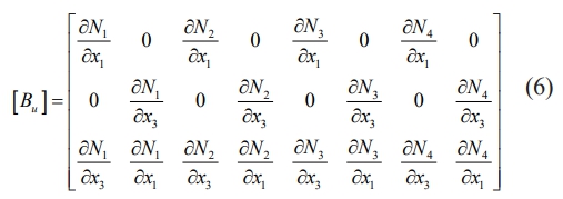
Where[Bu],[Bf]and[By] depicts the relationships between strain and displacement, magnetic field and potential, and electric field and potential, respectively and it can be written in eq. (6), (7) as [29],

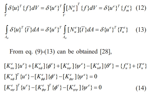
The virtual displacement concept can be expressed in eq. (8) as follows while taking the body force { f } into account [5],

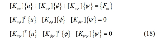
where {t͞͞} symbolizes the elements that make up the traction vector. Substituting the constitutive relations from eq. (1) into eq. (8) and these equations can be obtained by simplifying [5],

The following matrix form can be used to explain the above equation,

where various matrices in the elemental level in the eq. (15) are given as [29],

Eq. (15) can be used to write the equation of motion by collecting the contributions of each element [30],
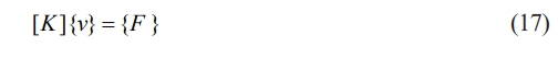
where 
Where {u} = {u1, u3}T . The behaviour of the magnetoelectroelastic material in a temperature environment can be examined using the equation of motion (17). The goal is to examine the sensory behaviour of the sensor patch that is integrated onto the upper surface of a mild steel beam. Mild steel is a frequently used material in many different situations. The equation cited above has been simplified given certain assumptions. The aim is to investigate how the sensor patch functions given these factors,
1. Absence of traction force, free charge density, body force, and free current density.
2. An explicit evaluation of the temperature distribution is made. In this study, the relationship between mechanical and thermal fields is taken into account.
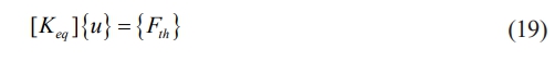
The finite element equation can be written as [31],
The process of obtaining the equivalent stiffness matrix involves the elimination of the electric potential φ and magnetic potential ψ from eq. (18) using conventional condensation procedures. Nodal thermal displacements are calculated using the resulting stiffness matrix [Keq] and load vector {Fth} [31].
where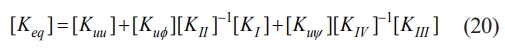
where

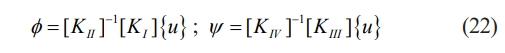
The task of solving the fully coupled magneto-electro-elastic finite element equation (19) under thermal loading has been accomplished. To evaluate the thermal load vectors and elemental stiffness matrices’ integrals, the Gaussian integration technique with four points has been employed. By assembling the elemental stiffness matrices and thermal load vectors, the global stiffness matrices and global thermal load vectors have been obtained. To assess the thermal displacements, the linked equivalent stiffness matrix [Keq] of the magneto-electro-elastic system has been inverted. After evaluating the thermal displacements, the electric and magnetic potentials at each nodal point can be calculated using equations (23) [31].
To thoroughly assess the precision of the current approach, it is crucial to take into account the piezoelectric sensor. In particular, a uniform temperature increase of 50 °C was induced in the mild steel beam that holds the sensor patch together. The resulting variation in electric potential was then compared with the outcomes obtained from the commercial finite element program ANSYS [32]. Various volume fraction piezoelectric sensors, made of Barium Titanate BaTiO3, were analysed [33].
Using the 2-D Plane13 4-node coupled field solid element with three nodal dof (displacements in x direction and z direction, and electric potential), an ANSYS model of a cantilever mild steel beam embedded with sensor material was created. However, the behaviour of magnetostrictive sensor materials lies beyond the scope of the finite element program ANSYS. The sensor patch and mild steel beam were laid out as follows: length of the beam (l) = 100 mm, thickness of the beam (t) = 3 mm, length of the sensor patch (ls) = 3.33 mm, thickness of the sensor patch (ts) = 0.5 mm.
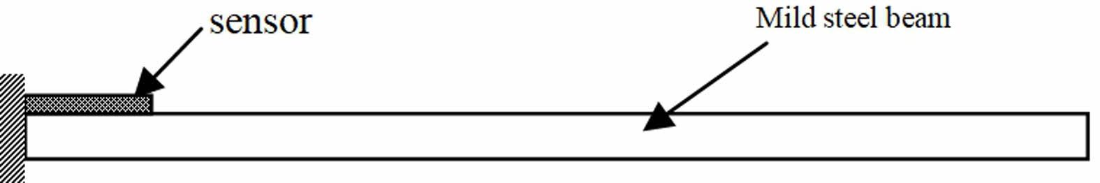
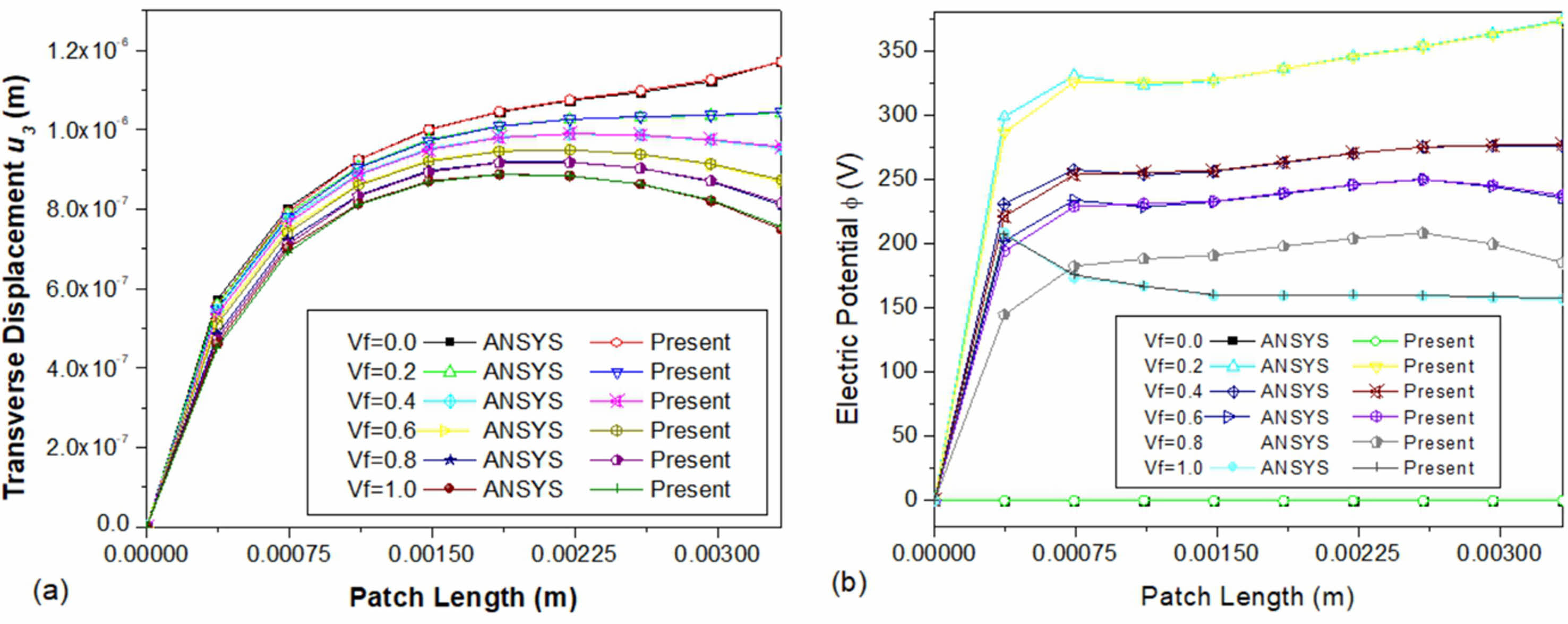
Figure 1 provides a schematic diagram of a clamped-free beam with a sensor patch implanted at the clamped end. The top surface of the sensor patch demonstrates transverse displacement and electric potential fluctuations, as shown in Fig. 2(a) and (b). These results are for clamped-free beams with different volume fractions of sensor patches without the pyroelectric coupling effect, and a uniform temperature increase of 50 °C was considered. As the results indicate, there is remarkable agreement between the current formulation and the ANSYS.
|
Fig. 1 Schematic diagram of cantilever mild steel beam with sensor patch. |
|
Fig. 2 Variation of (a) transverse displacement u3 (b) electric potential Φ on the top surface of the sensor patch along the length. |
This section provides a detailed analysis of the materials used in three different types of sensors, namely piezoelectric (PZT-4), magnetostrictive composite (Terfenol-D epoxy), and multiphase magnetoelectroelastic (BaTiO3-CoFe2O4). The comparative analysis primarily focuses on the impact of these sensor materials on their location during a uniform temperature rise. To conduct the study, a foundation structure made of mild steel was used, and a sensor patch was inserted in its upper surface. The researchers analyse the variation of the sensor’s electric and magnetic potential for various locations and boundary circumstances.
The study involves a uniform temperature rise of 50 °C, and the sensor patch is constructed using three different materials, including piezoelectric material PZT-4, magnetostrictive material Terfenol-D epoxy, and multiphase magnetoelectroelastic material (BaTiO3-CoFe2O4) with varying volume fractions. The researchers conduct tests on the clamped-free beam’s fixed end, middle, and free end patches to evaluate the behaviour of the sensor.
To ensure the accuracy of the results, the sensor patch positions are taken into consideration at the fixed end and middle of the beam. In the case of a clamped-clamped beam, the researchers consider the uniform temperature rise and symmetry boundary constraint about the middle of the beam. The computational case data is presented in Table 1 [34, 35], which lists the sensor materials that are polarized along the z-axis and their corresponding material constants.
It is important to note that the mild steel beam’s material property includes a Young’s Modulus (E) of 210 GPa, Poisson ratio of 0.3, Thermal expansion coefficient of 12.0×10⁻⁶ 1/K, and Magnetic permeability coefficient of 2.51×10⁻⁴. The thermal expansion coefficient for PZT-4 is derived [36], and for Terfenol-D epoxy, it is assumed as 1.2×10⁻⁶ 1/K. The multiphase magnetoelectroelastic material with varying volume percentages is composed of a piezo-magnetic (CoFe2O4) matrix supplemented with a piezoelectric (BaTiO3) material [37, 38]. Pure piezoelectric (BaTiO3) material has a Vf = 1.0 value, while pure piezo-magnetic (CoFe2O4) material has a Vf = 0.0 value. The multiphase magnetoelectroelastic coefficient of thermal expansion is taken from the literature [32, 33, 39].
To simulate the system, the researchers use a finite element model of the beam with 1656 two-dimensional 4-node plane stress elements with 3874 displacement dof, 40 electric dof, and 1937 magnetic dof. Overall, the study provides valuable insights into the impact of different sensor materials on their location during a uniform temperature rise [40].
Clamped-free (c-f) boundary condition’s effect on the variation of electric and magnetic potential
Sensor patch located at clamped end
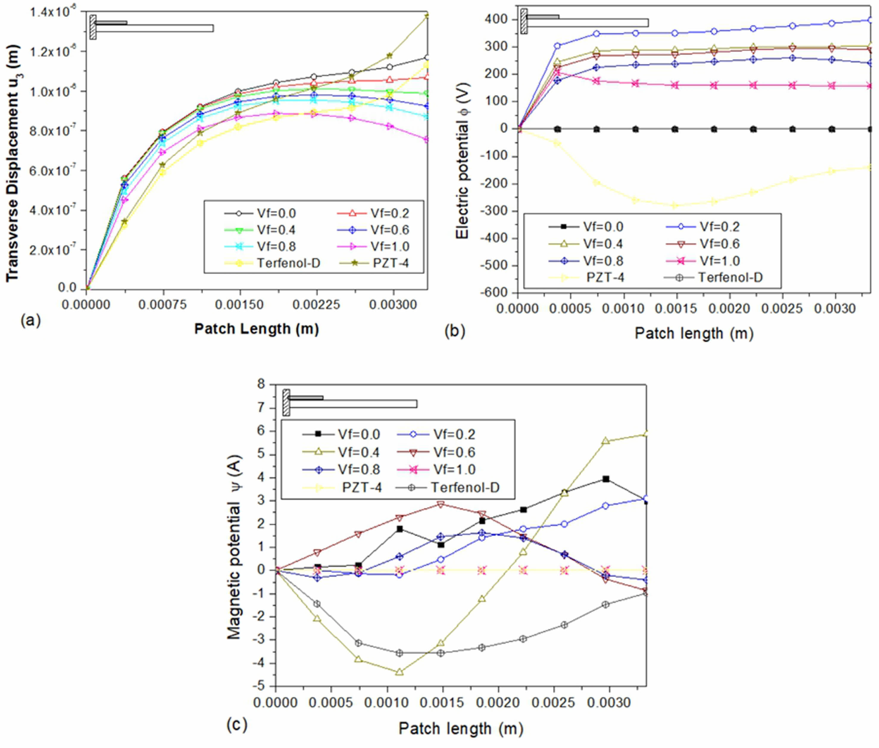
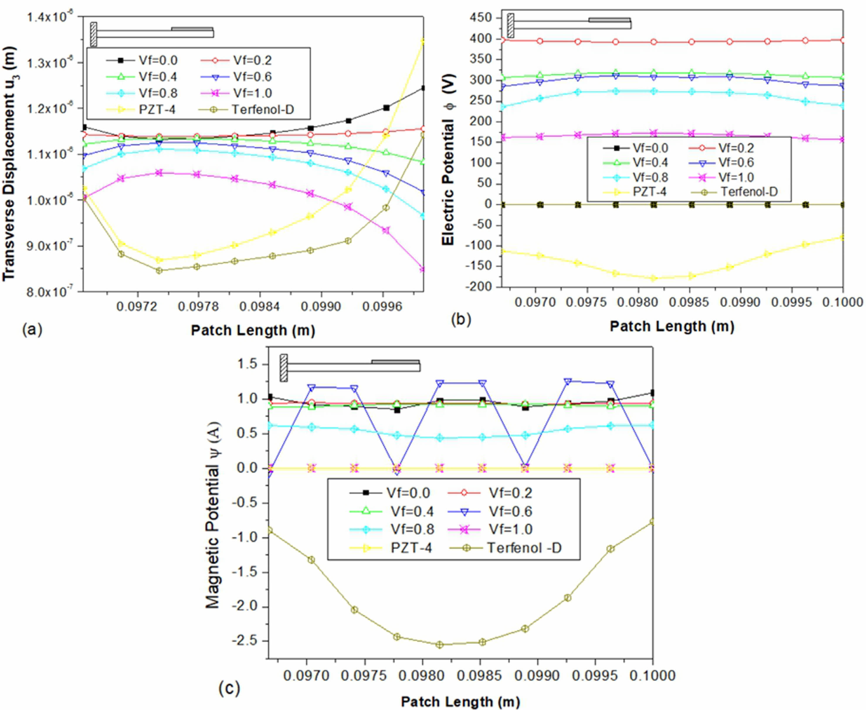
The data presented in Fig. 3(a)-(c) demonstrates the various transverse displacement electric and magnetic potential values for three distinct sensor patches. These patches are fabricated using piezoelectric (PZT-4), magnetostrictive (Terfenol-D epoxy), and a multiphase magnetoelectroelastic material. The sensor patches are located at the clamped end of the beam and feature different volume fractions. Notably, the PZT-4 material exhibits the highest transverse displacement (w) at the free end compared to the other materials. Furthermore, the multiphase magnetoelectroelastic patch with Vf = 0.0 has a higher transverse displacement than other volume fractions. For volume fractions ranging from 0.0 to 1.0, the transverse displacement decreases as the volume fraction increases. From Fig. 3(b), it is noticed that for multiphase magnetoelectroelastic with a volume fraction of 0.2, the electric potential is higher as compared to other sensor materials. From Fig. 3(c), it is observed that the magnetic potential for volume fraction 0.4 of magnetoelectroelastic is 5.87 A and maximum among the other materials at the sensor’s free end.
Sensor patch situated in the beam’s centre
The study delves into the behaviour of the sensor patch positioned in the centre of the clamped-free beam. The research aims to gain a better understanding of how the patch’s position influences the sensor’s performance. The study examines the transverse displacement (w), electric potential (φ), and magnetic potential (ψ), represented in Figs. 4(a)-(c), respectively. The results show that the displacement of PZT-4 is higher on the right side tip of the sensor patch compared to the multiphase magnetoelectroelastic sensor material. The transverse displacement decreases as the volume fraction increases for volume fractions ranging from 0.0 to 1.0, with the maximum displacement occurring on the right side of the patch. In Fig. 4(b), the electric potential for multiphase magnetoelectroelastic with a volume fraction of 0.2 is larger and constant along the length of the sensor. On the other hand, the magnetic potential, seen in Fig. 4(c), is dependent on the volume fraction. At the centre of the sensor patch, Terfenol-D epoxy has a high magnetic potential with a magnitude of 2.06 A. The magnetic potential for the multiphase magnetoelectroelastic with a volume fraction of 0.6 oscillates along the length.
Sensor patch located at the free end
The diagram presented in Fig. 5(a)-(c) illustrates the variation of transverse displacement (w), electric potential (φ), and magnetic potential (ψ) in a mild steel beam that is clamped on one end and free on the other. A sensor patch is placed at the free end to monitor the behaviour of the beam. The results obtained from the sensor patch placed at the centre of the beam show similar behaviour, with no discernible differences in transverse displacement, electric potential, or magnetic potential. However, the numerical analysis indicates that the magnetic potential of the sensor patch fixed at the clamped end exhibits a more significant change than the patches located at the middle and free ends of the beam.
Influence of clamped-clamped (c-c) boundary condition on the variation of electric and magnetic potential
Patch of the sensor at the clamped end
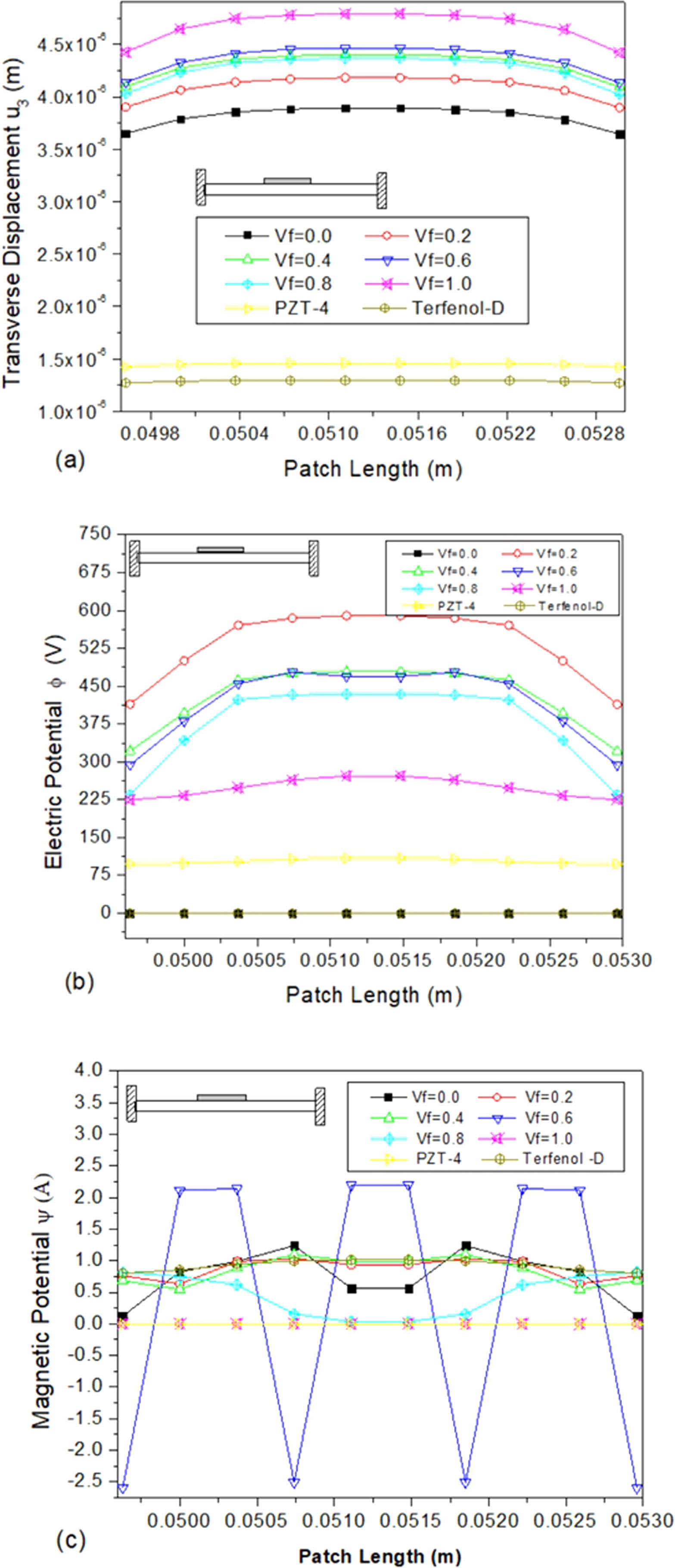
The sensors used in engineering applications, such as magnetostrictive or piezoelectric ceramic sensors, are affixed to structures and experience changes in electric and magnetic potential due to the influence of boundary conditions. Fig. 6(a)-(c) illustrates the varying transverse displacement, electric potential, and magnetic potential of a sensor patch bonded at the clamped end and subjected to clamped-clamped boundary conditions. The centre of the sensor patch experiences the highest displacement, as depicted in Fig. 6(a). Meanwhile, the electric potential is highest at the edges of the sensor patch and is higher than the clamped free boundary condition. Fig. 6(c) shows that the behaviour is comparable to that of a clamped-free boundary condition. This information is crucial for engineers who use these sensors to understand the behaviour of the structure that they are measuring, allowing them to make informed decisions about how to improve it.
Sensor patch situated in the beam’s centre
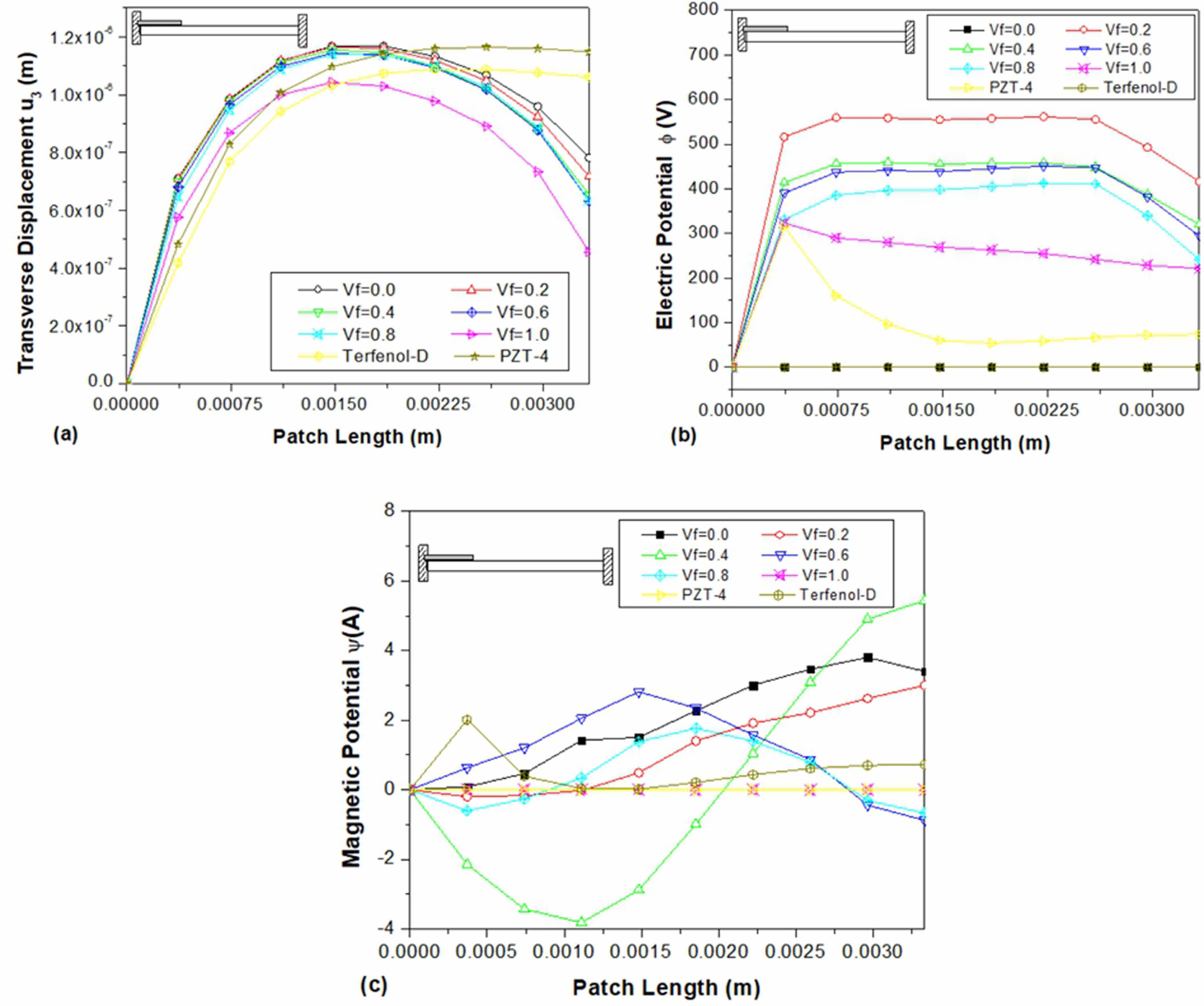
Figure 7(a), is a depiction of the variation in transverse displacement for the sensor patch located at the middle of the beam, where the boundary conditions are clamped-clamped. It is noticeable that the displacement values are larger than those observed in the clamped-free boundary condition. This, in turn, results in a higher induction of electric potential, which can be seen in Fig. 7(b). For magnetoelectroelastic materials consisting of multiple phases and having a volume percentage of 0.6, the magnetic potential oscillates significantly over the length of the sensor patch, with a high magnitude.
Effects of the simply supported (s-s) border condition on the electric and magnetic potential variation
Location of sensor patch at s-s end
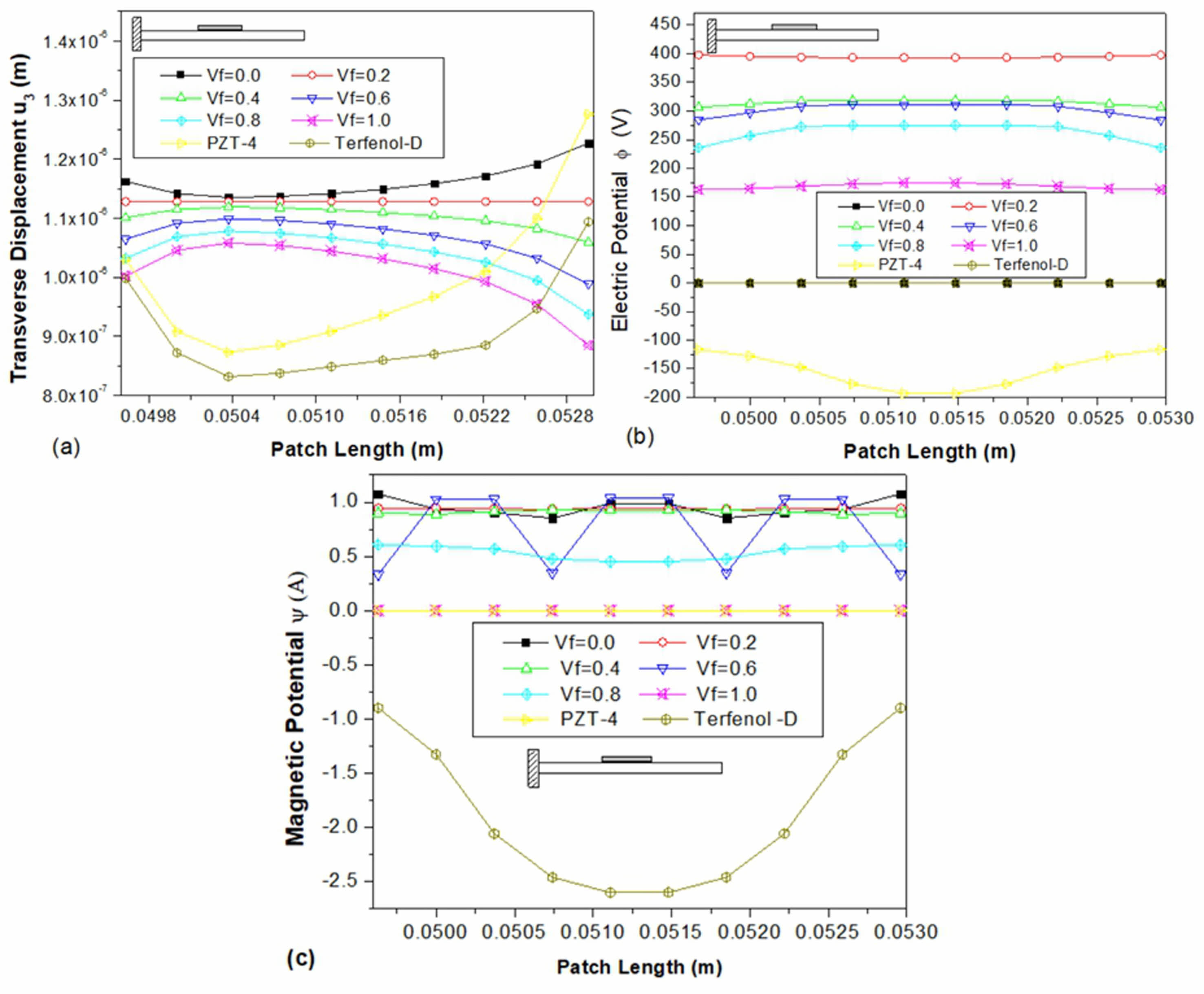
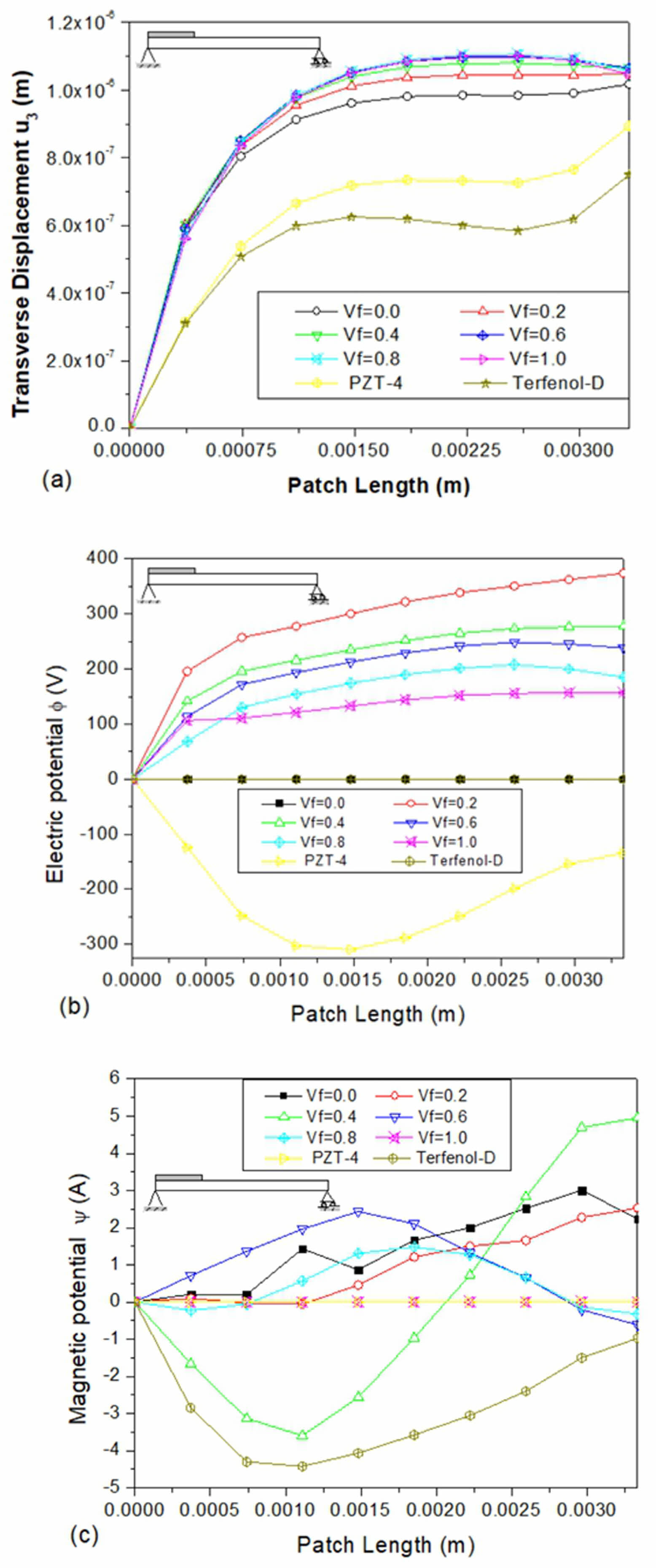
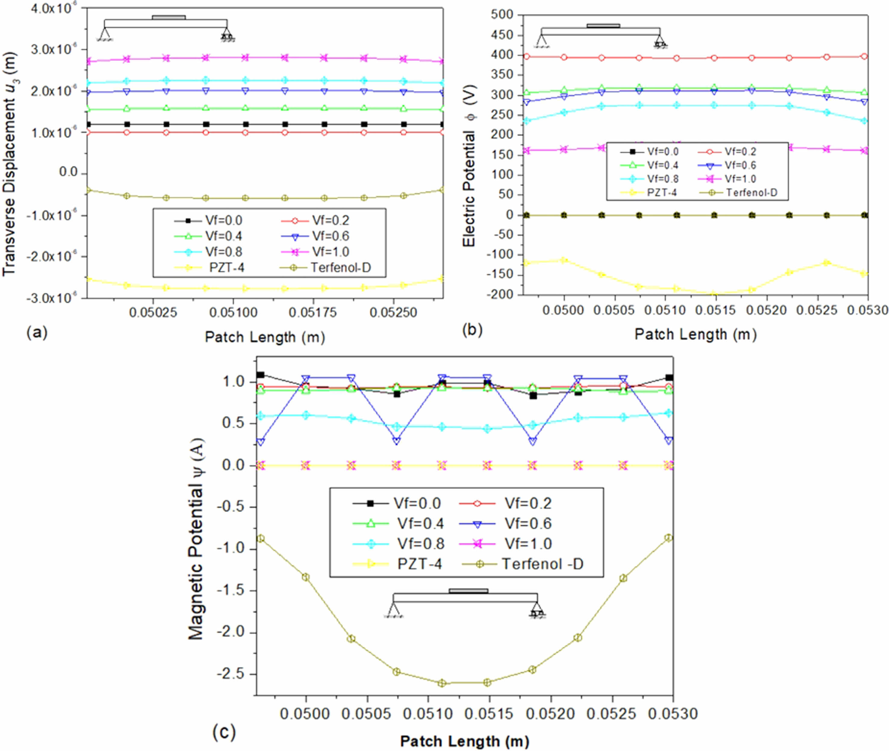
The present study aims to analyze the sensory response of a simply supported mild steel beam that has been embedded with sensor materials consisting of multiphase magnetoelectroelastic materials with different volume fractions, PZT-4, and Terfenol-D epoxy. To achieve this, a finite element formulation has been utilized. Specifically, the study focuses on the transverse displacement (w), electric potential (f), and magnetic potential (ψ) of the beam. It is assumed that in the context of a sensor patch, the transverse displacement, electric potential, and magnetic potential will remain zero at the simply supported end of the beam. Additionally, the electric potential at the interface between the mild steel and piezo ceramic bottom surface should also remain zero [36]. To obtain the desired results, the generalized displacements and electric and magnetic potential were analysed on the upper surface of the sensor patch under a uniform temperature rise of 50 °C. A comparison was then made by displaying the differences in maximum values of the results along the length of the sensor patch at the simply supported end. The obtained results were then compared to those of multiphase magnetoelectroelastic, piezoelectric material (PZT-4), and magnetostrictive material (Terfenol-D epoxy).
The comparison revealed that the transverse deformation of the multiphase magnetoelectroelastic sensor patch was higher than that of the PZT-4 and Terfenol-D epoxy sensor materials. Furthermore, the electric potential of the multiphase magnetoelectroelastic material was higher than that of the PZT-4 sensor patch with the volume fraction of 20% showing a higher potential than the other volume fractions. Similarly, the magnetic potential of the multiphase magnetoelectroelastic material was higher than that of the Terfenol-D sensor patch, with the volume fraction of 40% showing a higher potential than the other volume fractions. These findings indicate that the multiphase magneto electro-elastic sensor patch may be better suited for certain applications. Fig. 8
Sensor patch is in the centre of the beam
The following analysis presents a comparative study of the transverse displacement (w), electric potential (φ), and magnetic potential (ψ) of a simply supported beam bonded with a sensor material at its mid-span. The study considers the behaviour of multiphase magnetoelectroelastic sensor material, PZT-4, and Terfenol-D epoxy material with different volume fractions. The plots presented in Fig. 9(a)-(c) demonstrate the variance of these properties across the different materials and volume fractions.
The results indicate that the displacement of the magnetoelectroelastic material with a volume fraction of 100% is higher compared to other materials, as shown in Fig. 9(a). The displacement values increase as the volume fraction increases, except for the volume fraction of 0%. Similarly, Fig. 9(b) shows that the electric potential of the magnetoelectroelastic material with a 20% volume percentage is relatively large, as opposed to a volume fraction of 0% and Terfenol-D material, where it is zero due to the absence of piezoelectric constants.
Furthermore, Fig. 9(c) illustrates that the magnetic potential of Terfenol-D epoxy is higher than that of the multiphase magnetoelectroelastic materials. The value is zero for a volume fraction of 100% and PZT-4 material, which is due to the absence of piezomagnetic constants. For a volume fraction of 60%, the values oscillate.
In conclusion, the findings from this study provide insights into the behaviour of different materials and their volume fractions concerning transverse displacement, electric potential, and magnetic potential. These results can be useful in designing and optimizing the performance of sensor materials for various practical applications.
|
Fig. 3 Variation of (a) transverse displacement u3 (b) electric potential Φ (c) magnetic potential ψ along the length on the top surface of the sensor patch bonded at the fixed end. |
|
Fig. 4 Variation of (a) transverse displacement u3 (b) electric potential Φ (c) magnetic potential ψ along the length on the top surface of the sensor patch bonded at the middle of the beam. |
|
Fig. 5 Variation of (a) transverse displacement u3 (b) electric potential Φ (c) magnetic potential ψ along the length on the top surface of the sensor patch bonded at the free end of the beam. |
|
Fig. 6 Variation of (a) transverse displacement u3 (b) electric potential Φ (c) magnetic potential ψ along the length on the top surface of the sensor patch bonded at the fixed end. |
|
Fig. 7 Variation of (a) transverse displacement u3 (b) electric potential Φ (c) magnetic potential ψ along the length on the top surface of the sensor patch bonded at the middle of the beam. |
|
Fig. 8 Variation of (a) transverse displacement u3 (b) electric potential Φ (c) magnetic potential ψ along the length on the top surface of the sensor patch bonded at the simply supported end of the beam. |
|
Fig. 9 Variation of (a) transverse displacement u3 (b) electric potential Φ (c) magnetic potential ψ along the length on the top surface of the sensor patch bonded at mid-span of the simply supported beam. |
|
Table 1 Material property for Piezoelectric (PZT-4) [32], magnetostrictive composite Terfenol-D epoxy [35] and multiphase magneto electro elastic [34] with volume fraction Vf of BaTiO3 – CoFe2O4. |
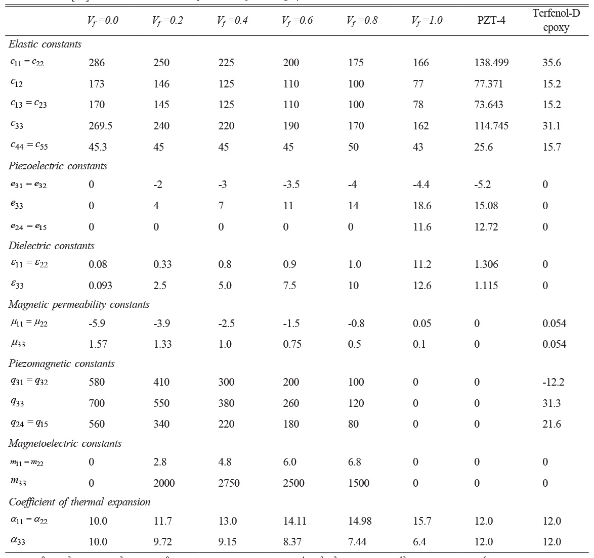
cij in 109 N/m2 , eij in C/m2 , eij in 10-9 C/Vm, qij in N/Am, μij in 10-4 Ns2 /C2 and mij in 10-12 Ns/VC, αij in 10-6 1/K |
The present study numerically investigates the effective placement of piezoelectric, magnetostrictive, and magnetoelectroelastic sensors on a mild steel base beam. The behaviour of these sensors is predicted and compared using the finite element method under clamped-free, clamped-clamped, and simply supported boundary conditions based on their electric and magnetic potential. The study also takes into account a uniform temperature rise of 50 °C. The following conclusions have been drawn.
1. For The Patch Situated at the clamped, middle, and free ends of the beam, a multiphase magnetoelectroelastic sensor with a volume fraction of 0.2 exhibits a greater electric potential. In the case of a clamped-free boundary condition, the variation in magnetic potential is greater for the sensor patch fixed at the clamped than for the patches at the middle and free ends of the beam.
2. The sensor patches with 0.4 volume fraction at the fixed end and 0.6 volume fraction in the middle of the beam under the clamped-clamped boundary condition exhibit greater variations in magnetic potential.
3. Under simply supported boundary conditions, the sensor patch with a 0.4 volume fraction positioned at the simply supported end exhibits a greater variation in magnetic potential.
The results of the numerical simulation indicate that sensor patches with volume fractions of 0.2 and 0.4 exhibit higher electric and magnetic potentials, respectively, under clamped-free, clamped-clamped, and simply supported boundary conditions. In a thermal environment, the optimal positioning of the sensor patch is contingent on the beam’s boundary conditions. For a clamped-free beam, the recommended placement is at the clamped end, while for a clamped-clamped beam, the middle of the beam is the optimal location.
- 1. R.D. Mindlin, Soc. Ind. Appl. Math. (1961) 282-290.
- 2. S.S. Rao and M. Sunar, AIAA J. 31[7] (1993) 1280-1286.
-

- 3. Rekha Rania, J.K. Juneja, K.K. Raina, and Chandra Prakash, J. Ceram. Process. Res. 13[1] (2012) 76-80.
-
- 4. M. Sunar and S.S. Rao, AIAA J. 35[3] (1997) 534-539.
-
- 5. M. Sunar, Ahmed Z Al-Garni, M.H. Ali, and R. Kahraman, AIAA J.40[9] (2002) 1846-1851.
-
- 6. H.S. Tzou and R. Ye, J. Vib. Acoust. 116[4] (1994) 489-495.
-
- 7. W. Nowacki, J. Therm. Stresses. 1[2] (1978) 171-182.
-
- 8. Manfred Kaltenbacher, Sebastian M. Schneider, Reinhard Simkovics, Hermann Landes, and Reinhard Lerch, Proc. Smart Mater. Struct. 4326 (2001) 160-168.
-
- 9. Tianli Zhang, Chengbao Jiang, Hu Zhang and Huibin Xu, Smart. Mater. Struct. 13[3] (2004) 473-477.
-
- 10. D.P. Ghosh and S. Gopalakrishnan, Smart. Mater. Struct. 14[6] (2005) 1462-1473.
-
- 11. Y.T. Keum, J.H. Kim, and B.Y. Ghooa, J. Ceram. Process. Res. 1[1] (2000) 74-79.
- 12. Kalyani Gurram and Pannirselvam N, J. Ceram. Process. Res. 24[3] (2023) 560-568.
-
- 13. Y.T. Keum and K.H. Auh, J. Ceram. Process. Res. 3[3] (2002) 141-145.
- 14. Hao-Miao Zhou and You-He Zhou, Smart. Mater. Struct. 16[1] (2007) 198-206.
-
- 15. J.M. Bakhashwain, M. Sunar, and S.J. Hyder, Arab. J. Sci. Eng. 29[10] (2004) 125-138.
- 16. Ce-Wen Nan, Phys. Rev. B. 50 (1994) 6082-6088.
-
- 17. Marco Avellaneda and Girish Harshé, J. Intell. Mater. Syst. Struct. 5 (1994) 501-513.
-
- 18. Y. Benveniste, Phys. Rev. B.51 (1995) 16424-16427.
-
- 19. Jin H. Huang and Wen-Shyong Kuo, J. Appl. Phys. 81 (1997) 4889-4898.
- 20. George R. Buchanan, Compos. B. Eng. 35[5] (2004) 413-420.
-
- 21. E. Pan and F. Han, Int. J. Eng. Sci. 43[3-4] (2005) 321-339.
-
- 22. Anandkumar R. Annigeri, N. Ganesan, and S. Swarnamani, J. Sound. Vib. 299[1-2] (2007) 44-63.
-
- 23. Nada Tassi, Abderrahmane Bakkali, Nadia Fakri, Lahcen Azrar, and Abdulmalik Aljinaidi. Compos. Struct. 280[15] (2022) 114896.
-
- 24. W.Q. Chen, Kang Yong Lee, and H.J. Ding, Int. J. Engg. Scie. 42[13-14] (2004) 1361-1379.
-
- 25. Liming Zhou and Fangting Qu, Compos. Struct. 315[1] (2023) 116984.
-
- 26. N. Sangeetha, V.M. Brathikan, R.K. Nitheeshwar and S. Jayabalu, J. Ceram. Process. Res. 23[4] (2022) 529-534.
-
- 27. Hong-Kyu Kwon, J. Ceram. Process. Res. 9[2] (2008) 192-197.
-
- 28. Y.T. Keum, J.H. Kima, and K.H. Auh, J. Ceram. Process. Res. 2[1] (2001) 9-15.
- 29. A. Kumaravel, N. Ganesan, and Raju Sethuraman, Multidiscip. Model. Mater. Struct. 3[4] (2007) 461-476.
-
- 30. Vincent McKoy, Phys. Scr. 21[3-4] (1980) 238.
-
- 31. A. Kumaravel, N. Ganesan, and Raju Sethuraman, Smart Mater. Struct. 16 (2007) 282-295.
-
- 32. ANSYS, in “Coupled field analysis guide” (ANSYS Inc., 2009) p. 1-282.
- 33. Sung-Pill Nam, Sung-Gap Lee, and Young-Hie Lee, J. Ceram. Process. Res. 9[1] (2008) 6-9.
-
- 34. Fernando Ramirez, Paul R. Heyliger, and Ernian Pan, J. Sound. Vib. 292[3-5] (2006) 626-644.
-
- 35. Y.X. Liu, J.G. Wan, J.M. Liu, and C.W. Nan, J. Appl. Phys. 94 (2003) 5118-5122.
-
- 36. N. Ganesan and Ravikiran Kadoli, Comput. Struct. 83[15-16] (2005) 1305-1319.
-
- 37. S.S. Madani, G. Mahmoudzadeh, and S. Abedini Khorrami, J. Ceram. Process. Res. 13[2] (2012) 123-126.
-
- 38. Adil Moutaouaffiq, Ali Didi Seddik, Abdelilah Rjeb, Mohammed Naciri Bennani, Mohamed Naji, and Salaheddine Sayouri, J. Ceram. Process. Res. 24[6] (2023) 954-962.
-
- 39. N. Ganesan, A. Kumaravel, and Raju Sethuraman, J. Mech. Mater. Struct. 2[4] (2007) 655-674.
-
- 40. S. Shanmugam, S. Mahalingam, and A. Ranjithkumar, J. Ceram. Process. Res. 24[3] (2023) 495-502.
-
 This Article
-
2024; 25(1): 119-130
Published on Feb 29, 2024
- 10.36410/jcpr.2024.25.1.119
- Received on Jan 4, 2024
- Revised on Jan 29, 2024
- Accepted on Jan 30, 2024
Services
- Abstract
introduction
basic equations
validation
results and discussions
conclusions
- References
- Full Text PDF
Shared
Correspondence to
- Dhanasekaran Rajagopal
-
Department of Mechanical Engineering, Adhiyamaan College of Engineering, Hosur, Tamil Nadu – 635 109, India
Tel : +919043793491 Fax: 04344-260573 - E-mail: dr.r.dhanasekaran@gmail.com
Clean-Energy Research Institute(CRI), Hanyang University, 222, Wangsimni-ro, Seongdong-gu, Seoul, 04763, Korea
E-mail: jcpr@hanyang.ac.kr