


- Cytotoxicity evaluation of Mg-2Al-1Nd alloy-coated MgF2 for biomedical applications
Baraa H. Al Khaqania,* and Nawal Mohammed Dawoodb,*
a,bCollege of Materials Engineering, University of Babylon, Iraq
This article is an open access article distributed under the terms of the Creative Commons Attribution Non-Commercial License (http://creativecommons.org/licenses/by-nc/4.0) which permits unrestricted non-commercial use, distribution, and reproduction in any medium, provided the original work is properly cited.
Mg-Al-based alloys have grown in popularity as possible biomaterials for various biological purposes due to their ability to degrade and biocompatibility. For biological conditions, the resistance of corrosion magnesium alloys is still an issue. By altering the surface of the Mg-2Al-1Nd alloy, MgF2 coatings were created using the ultrasonically treated fluoride method (UHF) to decrease the rate of biocorrosion and cytotoxicity. The coating was approximately 488.1 nm thick, on average. According to the results of cytotoxicity, after 48 hours of culture, the growth of MC3T3-E1cells and L929cells were widely distributed on MgF2 coated Mg-2Al-1Nd alloy surface; a small number of cells were observed on the uncoated alloy samples, but the MgF2 film coating demonstrated the alloy’s minimal cytotoxicity and excellent biocompatibility. In summary, fluorite chemical conversion coating has shown benefits on the Mg-2Al-1Nd alloy’s enhanced cell responsiveness. It should be a helpful technique for modifying the surface of various magnesium alloys used in biomedical applications.
Keywords: Mg alloys, Ceramic Coating, Cytotoxicity, Biomaterials, Biomedical applications.
The field of biomedical applications is constantly looking for novel materials that work well in the surroundings of living things. Mg-Al alloys have garnered significant interest among the materials under consideration for biomedical applications because of their natural biodegradability and mechanical properties compatible with the human musculoskeletal system [1, 2]. The sensitivity of magnesium alloys to quick corrode in biological environments must be overcome before their full potential may be realized in biomedical applications. In this sense, the Mg-2Al-1Nd alloy shows a beneficial balance between strength and corrosion resistance, showing potential for use in implantable medical devices such as orthopaedic implants, cardiovascular stents, and other devices [3]. Researchers have looked into coatings to improve the performance and biocompatibility of magnesium-based biomaterials since they understand how vital corrosion control is. Bioceramic materials have found widespread application in bone tissue, biomedical, dentistry and medicine with their adaptability and functionality [5, 6]. Biologically originated ceramic materials are much more preferred, making them proper for intimate contact with living tissues [4, 5]. Due to its biocompatibility and capacity to act as a barrier against the corrosive effects of physiological fluids, MgF2 stands out as an appealing option [6]. Cytotoxicity, a critical factor in biocompatibility evaluations, refers to a material’s effect on live cells. This study aims to close the distance between the alloy’s impressive mechanical capabilities and its security record when interacting with biological systems. In the following sections, we dig into the procedures used for alloy preparation, cell culture, and cytotoxicity testing [7]. The findings comments sections provide explanations of the patterns that were noticed, and they conclude with a thorough assessment of a covered alloy’s potential for use in applications in medicine. Magnesium’s corrosion resistance has increased thanks to the fluoride conversion coating, although it has not yet been used in medical settings. In earlier fluoride conversion coating tests, J. Sun discovered that applying an ultrasonic cleaning coating to Mg surfaces accelerated the pace of colour change. According to this study, as contrasted with fluoride conversion-coated Mg and Mg alloy, the corrosion-resistant endurance of fluoride conversion-coated Mg can be enhanced further by ultrasonic treatment [8]. Because of the strong chemical bonding of the base material, recent improvements make the treatment with fluoride feasible for creating a safe chemical fluoride conversion coating (MgF2) for considerable Mg alloy protection from corrosion. The authors found that fluorine treatment could reduce WE43 Mg alloy corrosion by half. Fluoride therapy is used [9]. The corrosion resistance of the Mg-3Zn-0.5Er alloys was increased by the Authors’ formation of a homogeneous fluoride conversion layer. The film creates hydrogen (H2) throughout fluorine treatment, producing a porosity layer. Due to the fluoride conversion layer’s typical thinness (16-18 µm), the anti-corrosion capacity and coating layer are frequently below the bar [10]. According to numerous studies, the fluoride supplement is most effective as a preventative measure. Therefore, more research is needed to create an accurate fluoride conversion coating with the necessary protective qualities [11]. The current study, which examines the cytotoxicity and biocompatibility of Mg-2Al-1Nd alloy covered with magnesium fluoride (MgF2), delves into the field of biomaterials engineering in this context.
Materials and preparation of alloy
The new Mg alloy bar was produced by the investment casting technique [12]. The test piece alloy was cut by wire cutting to a disc with dimensions (12 mm φ) and (3 mm high) machined. These specimens were then physically polished to a grit of 2000 and, by ultrasound, treated in a solution of acetone, 100% ethanol, and distilled water. A specially designed multifunction coating apparatus (Technol Science Co., Ltd., China) is coated with a thin film. The first treatment involves immersing the sample in a boiling 20% sodium hydroxide solution for three hours, followed by immersion in a diluted acid solution. For the UHF (ultrasonic immersion fluoric acid) coating procedure, the samples were put in locked plastic beakers and submerged in a 48% hydrofluoric acid solution at a rate of 20 ml/cm2 [13]. After that, the plastic beakers were left in an ultrasonic cleaner (SAEHAN SH-2100; ultrasonic frequency: 50-60 kHz; output: 100 W) set to run for 3 hours at room temperature. After three distilled water washing cycles, treatment samples were dried [14].
Characterization of Alloy
The chemical composition of the casting alloy (AN21) was ascertained by X-ray fluorescence analysis, as presented for the alloy in Table 1.
Characterization of Coating
Investigate the surface layer’s morphology by using A scanning electron microscope (TESCAN and Model: VEGA3SBH), Precipitation behaviours on the coated surface were investigated by SEM observation [15]. Surface morphologies, pores, and fractures were determined through the use of image analysis. Atomic force microscopy (AFM (Digital Instruments, CSPM-AA3000), which has a distance accuracy of 1 m) is used to identify the layer’s thickness.
Corrosion behavior
Electrochemical behaviour was studied using potential dynamic polarization (PDP) and electrochemical impedance spectroscopy (EIS). The potential dynamic polarization (PDP) test and the open-circuit potential (OCP) test were carried out in a standard three-electrode cell with a three-electrode configuration. The experiments were immersed in phosphate buffer saline solution with PH 7.2 at 37 °C; the platinum plate was used as the reference electrode (RE), the working electrode uncoated and coated alloys and a saturated calomel electrode, the exposed area of the specimens was 1.13 cm2. A short-term OCP test was conducted for one hour before the potential dynamic polarization test to guarantee a steady condition of alloys. Following the OCP test, PDP measurements were taken at a voltage of -240 mV (OCP of each sample). The corrosion rate was determined using equation (1) according to ASTM G102 [16, 17].
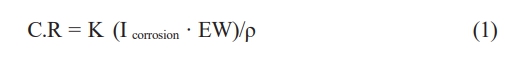
Where: C.R is the corrosion rate (mm/y), k=3.27×10⁻³ mm/g, ρ is the density of magnesium alloy, and Icorr is the current density E.W. = equivalent weight.
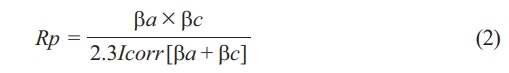
The corrosion rate of each specimen was determined from the Tafel curves, Which were used to calculate the potential and current density. Testing the alloy’s corrosion resistance is one of the main goals of this article. Phosphate buffer saline (PBS) solution of composition (in g/L) as [18]: [8.006 NaCl, 0.201 KCl, 0.240 KH2PO4 and 1.420 Na2HPO4, and deionized water] (PH 7.2) at 37 °C. Electrochemical impedance spectroscopy (EIS) was used. A change in intensity of 10 mV (OCP after 1 hour) and an operating frequency range of 100 kHz to 50 MHz. After assessing and matching powered comparable circuits to EIS data using the Gamry Echem Analyst program (Gamry Instruments, Inc.), the polarization resistance (R p) was calculated using the fitting equation below:
They started at 0.2 V and went up to +0.6 V vs OCP, with an average scan rate of 1 mV/s [19].
In vitro cytotoxicity test
Cytotoxicity evaluations according to the internationally recognized norm ISO 10993-5 were carried out as had been characterized to assess the cytotoxicity of the Mg-2Al-1Nd/MgF2 alloys [20]. To evaluate the harmful effects of AN21alloy, bovine fibroblast cell lines (L929) and bovine calvarial preosteoblasts (MC3T3-E1) are used. The cells cultured in the environment for cultivating serum free of L929 and MC3T3-E1 were Dulbecco’s modified eagle medium (DMEM; Invitrogen, USA) low required media alpha-MEM; Invitrogen). For each media, further amounts of 1% penicillin/streptomycin (P/S; Invitrogen) and 10% fetal bovine serum (FBS; Thermo, USA) were made. The HUVEC cell culture media comprised endothelium cell medium (ECM; ScienCell, USA), 1% endothelial proliferation supplement (ECGS; ScienCell), 5% FBS, and 1% P/S. The cytotoxicity test involved indirect interaction with cells. Magnesium alloy specimens were cultivated in the three cell culture media listed above for 48 hours to prepare them for the related cell viability tests. Within biological circumstances, 37 °C, 5% CO2, and 95% humidity, with an extracting buffer surface area ratio of 3 cm2/ml by EN ISO standards 10993:12 [20, 21]. The first extraction, known as 100%, was made with an additional media to make the fewer concentrated versions (0%, 0.01%, 0.1%, 0.5%, 0.75%, and 1%) a smaller amount. To get the best adherence, cells were seeded on 96-well plates at a density of 5000 cells/100 l media/well and pre-cultivated with a standard cell culture medium for 24 h. After that, takes were added to the medium, and the cells continued to be cultured for cellular parameters for 24 and 48 hours, correspondingly. Employing, the viability of cells was evaluated. Before measuring spectrophotometrical absorption at a wavelength of 450 nm in the dual-mode microplate reader, 10 l CCK-8 was added to each well and incubated for two h at 37 °C. which was calculated according to the following formula [22]:

In this scenario, a negative result correlates with more cells developed in cell culture conditions. In order to understand the impact of metal cations on cells, the technology of induction-coupled plasma mass spectrometry (ICP-MS; Perkin Elmer Optima 7300DV, USA) was utilized to determine the amounts of magnesium and alloying elements (Al and Nd) ion in extraction. Moreover, 3 ml of a solution comprising L929 and MC3T3-E1 cells was seeded onto the specimens in six-well plates for a more thorough assessment of the binding of cells on magnesium base-alloy materials. This suspension contained 105 cells per millilitre. The samples were cultured for 24 hours and washed several times with Hank’s mixed salt solution. The specimens were then immersed in 2.5% glutaraldehyde solutions for one hour to enable the cells to bind on the surface of the metal. After that, the specimens were dehydrated for ten minutes each in a gradient ethanol/distilled water mixture (50%-100%) before being further dehydrated in a hexamethyldisilazane (HMDS; TCI, Japan) solution. The cell’s connection movement on the specimen’s surface was studied using optics microscopy.

Characterization and Morphology
The chemical compositions of the casting alloy (Mg-2Al-1Nd) were ascertained by X-ray fluorescence analysis, which is displayed in Table 2. The specimens used for metallography were cut and mechanically ground with sic paper at grades 800, 1200, and 2000. They were then cleaned with acetone using ultrasonic cleaning for five minutes, dried thoroughly, and prepared for another round of testing. A solution containing 100 millilitres of ethanol, 20 millilitres of distilled water, 12 grams of picric acid, and 6 millilitres of acetic acid produced chemical etching lasting 10-20 seconds [23, 24].
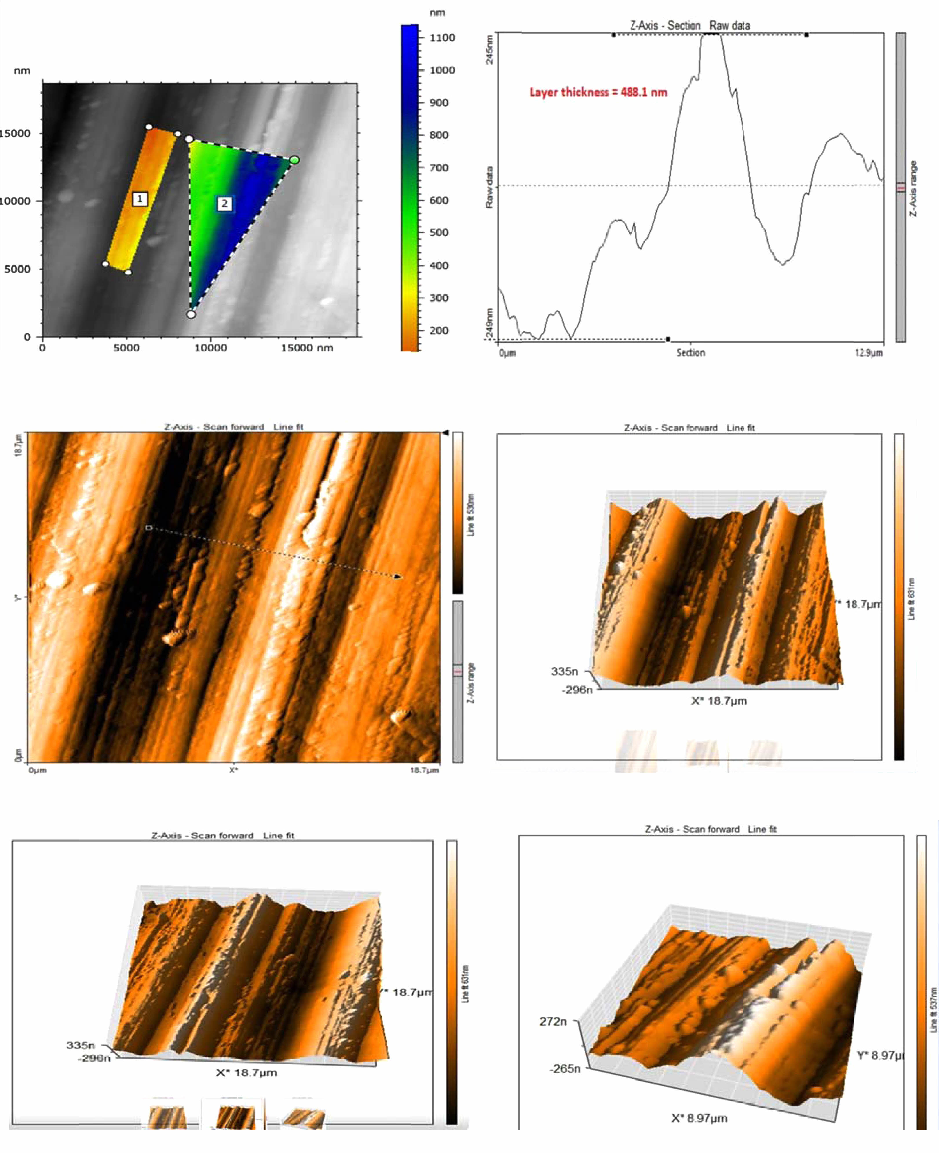
Thickness of layer coating
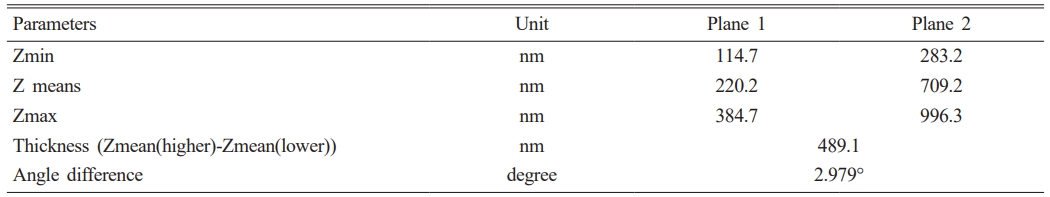
The film is significant to remember that, as shown in Table 3, the state of the AFM data and the AFM settings will determine how accurately the thickness is measured. It is advised to run numerous AFM scans on various sample locations and average the results for more accurate results. It is also vital to remember that the MgF2 layer’s thickness is not always constant. The placement on the substrate, the coating process, and the coating parameters can all affect the thickness. In order to accurately determine the average thickness, as shown in Fig. 1, measuring the thickness of the MgF2 layer at multiple sites is crucial.
Corrosion behavior
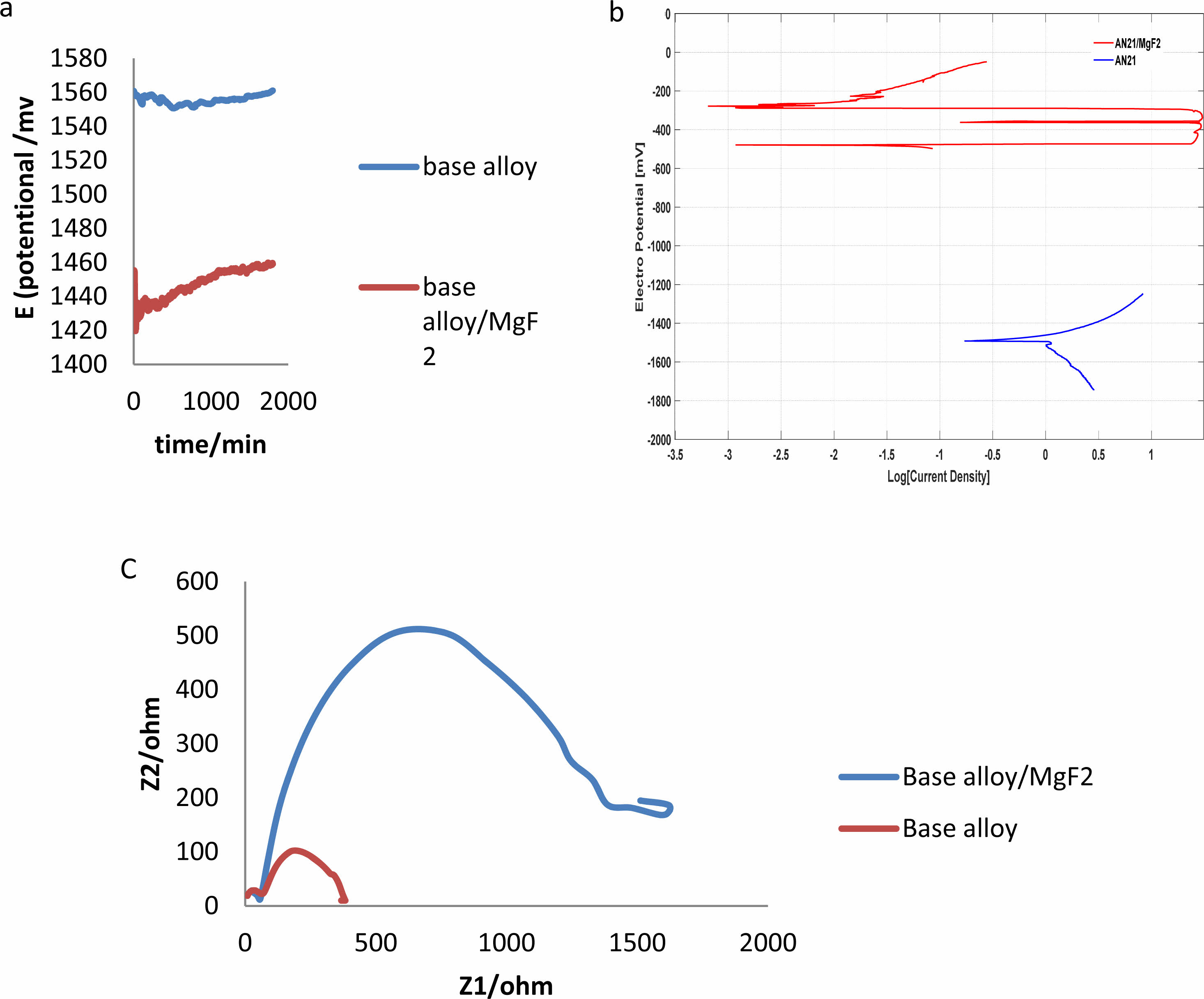
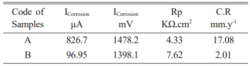
The OCP curves of the uncoated alloys are displayed in Fig. 2(a). The UHF-coated Mg-2Al-1Nd alloys showed significantly elevated OCP values after one hour. The standard PDP curves for both the uncoated and coated alloys can be seen in Fig. 2(b); the anodic curves indicate the dissolution of magnesium, whereas the cathode polarization curves represent the evolution of cathode hydrogen through water reduction. The increased corrosion rate is shown by the increased density of corrosion currents and lower corrosion potential [25]. The anodic and cathodic sections in the three specimens vary significantly from one another, depending on Tafel plots of corrosion potential and current density of corrosion for the uncoated and UHF-coated alloys. It can be observed that the specimen with UHF coating had significantly more excellent resistance than did the untreated and bare specimens, which indicates that fluoride coating with ultrasonic treatment significantly improves corrosion resistance. The test results are shown in Table 4, illustrating the enhancement of the alloy’s corrosion resistance with the MgF2 layer.
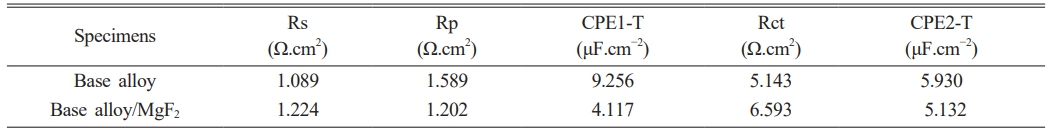
From the table above, we note that the age of the alloy after the coating has increased significantly in physiological solutions, which is also shown. Fig. 2(c) presented the results of EIS of alloy and alloy with MgF2 film, and this is due to the presence of a layer of magnesium fluoride that protects the surface of the alloy for a temporary period, and this is consistent with to use magnesium alloys in the field of surgery. Table 5
In Vitro Cytotoxicity
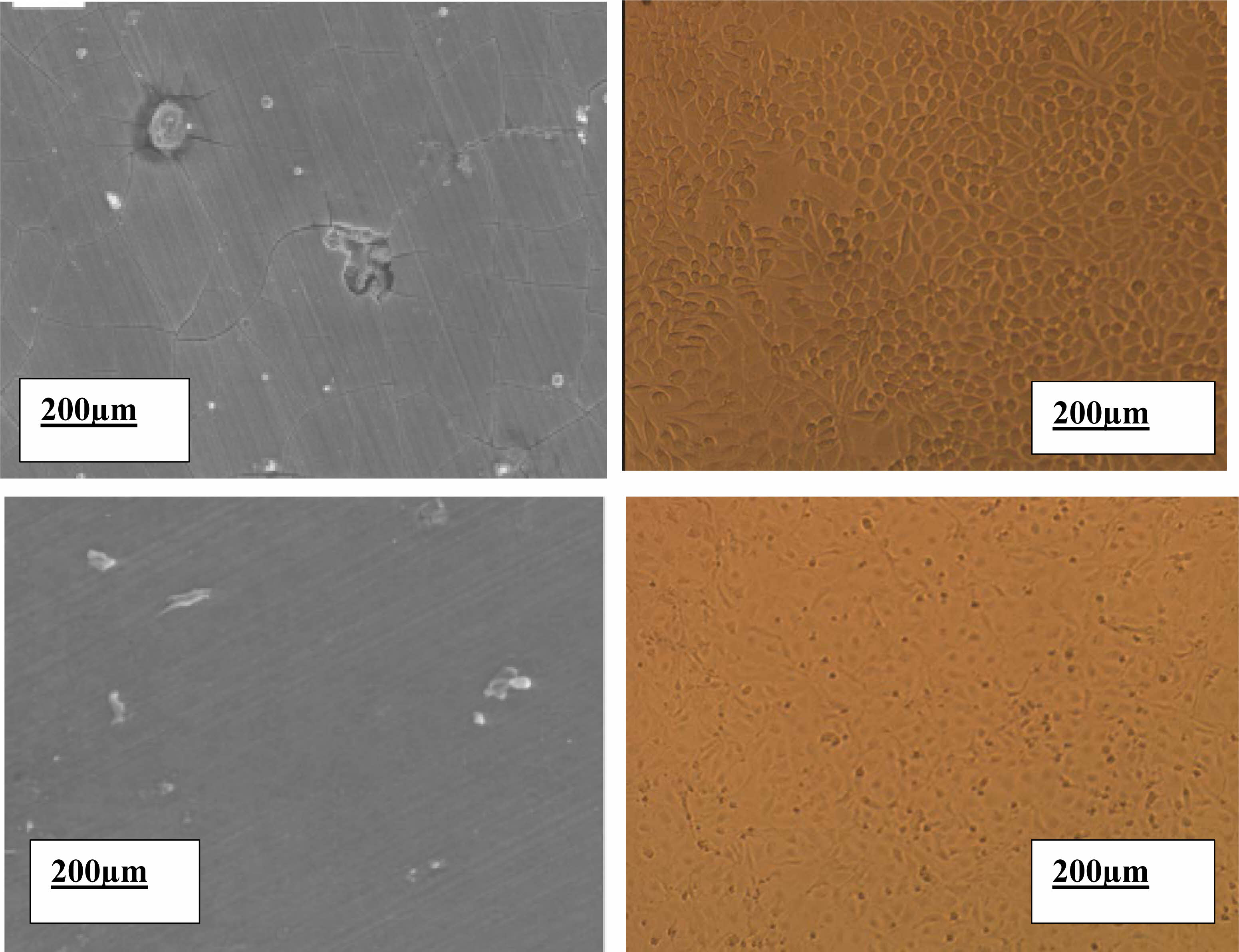
The cell shapes of L929 and MC3T3 cultures cultivated on Mg-2Al-1Nd alloy samples and MgF2-covered Mg-2Al-1Nd alloy samples for 48 hours. The reaction of the cells to Mg-2Al-1Nd alloy Disc and MgF2-coated Mg-2Al-1Nd samples differed significantly. The uncoated Mg-2Al-1Nd alloy sample experienced a pitting corrosion-related assault, interfering with cell adhesion activities. On the bare Mg-2Al-1Nd surface, only a few L929 cells with abnormally spherical forms and very few MC3T3 cells can be detected. As shown in Fig. 3, the MgF2 coating successfully delays the corrosion of the Mg-2Al-1Nd substrate and keeps the culture medium from becoming alkaline. According to Fig. 4, both L929 and MC3T3 cells had a healthy structure with several pseudopodia contacting the sample surface, an expanded morphology, and a cytoplastic. According to reports, F-only exhibited cytotoxicity at high concentrations (10-3 M) against UMR-106 cells [26]. The limited solubility of MgF2 (0.13 g/l) prevented the F-released from the MgF2 coating from reaching that level.
|
Fig. 1 Thickness of coating layer by AFM |
|
Fig. 2 Corrosion behaviour results (a) Open circuit potential (OCP), (b) Tafel curves and (c) EIS plot of Base alloy and alloy coated MgF2 in Phosphate buffer saline solution (PBS)with PH=7.2 at 37 oC. |
|
Fig. 3 Morphology of cells attached to the specimens after 48h culture. (a), (b): L929 on surface alloy A and B, respectively and (c), (d): MC3T3 on surfaces alloy A and B. |
|
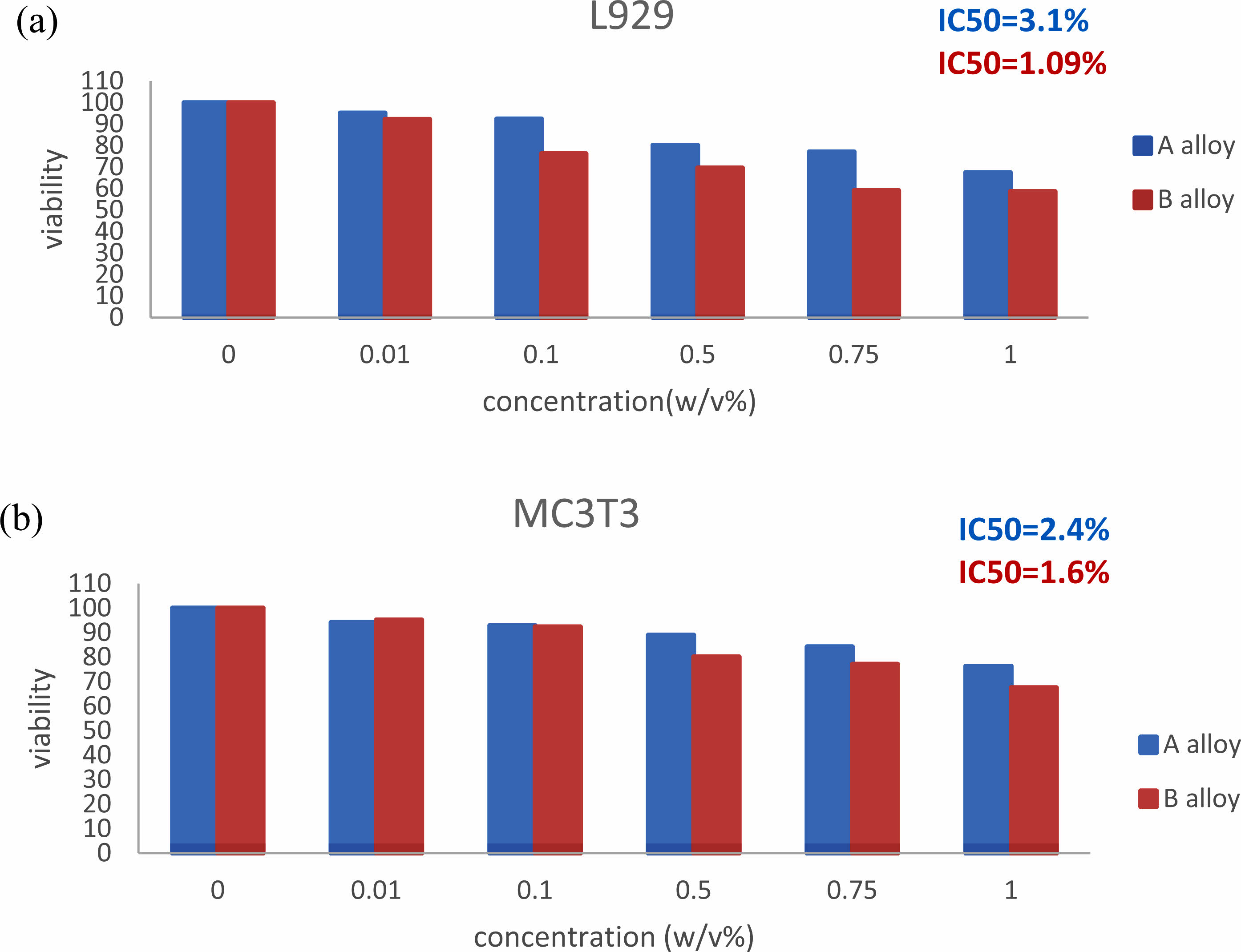
Fig. 4 Cell viability was expressed as a percentage of the viability of cells in control after two days’ culture in AN21 alloy extraction medium with different dilution factors 0, 0.01, 0.1, 0.5, 0.75, and 1%, respectively. (a) L929; (b) MC3T3-E1. Changes in cell viability are shown by an asterisk among categories of extracting dilute more than eight times and the medium containing 1% concentration of extraction (Pearson ˂ 0.05). |
|
Table 4 Improve shelf life for A and B alloys in Phosphate buffer saline (PBS) solutions. |
|
Table 5 Impedance parameters of Mg-2Al-1Nd alloy in Phosphate buffer saline solutions at 37 °C |
The ultrasonic conversion fluorite method has successfully deposited the protective layer MgF2 on Mg-2Al-1Nd alloy. It has also been found that the formation of this coating layer increases the alloy’s biocompatibility and reduces cytotoxicity compared to the alloy without coating. During a 48-hour culture, L929 and MC3T3-E1 cells adhered and dispersed evenly on the surface of the MgF2-coated samples in the direct cell assay. The MgF2 layer also demonstrated enhanced efficacy in safeguarding the magnesium alloys and regulating the rate of Mg-2Al-1Nd alloy deterioration.
The Ministry of Higher Education and the University of Babylon are gratefully acknowledged. This research was carried out in the laboratory department of metallurgy at the University of Babylon.
- 1. F. Kiani, C. Wen, and Y. Li, Acta Biomater. 103 (2020) 1-23.
-

- 2. L. Wang, Z. Lou, K. Jiang, and G. Shen, Adv. Intell. Syst. 1[5] (2019) 19-40.
-
- 3. J. Tan and S. Ramakrishna, Appl. Sci. 11[5] (2021) 68-61.
-
- 4. S.A. Doğdu, C. Turan, T. Depci, and D. Ayas, J. Ceram. Process. Res 2[3] (2021) 356-361.
-
- 5. J. Rohan, D. Thenmuhil, R. Umapriya, and D. Varatharajan, J. Ceram. Process. Res 23[1] (2022) 22-28.
-
- 6. W. Peng, Y. Chen, H. Fan, S. Chen, H. Wang, and X. Song, Materials 16[2] (2023) 682-689.
-
- 7. R.B. Heimann, Surf. Coat. Technol. 24[5] (2021) 121-127.
- 8. J. Sun, S. Jin, B. Zhao, H. Cai, L. Sun, X. Xuan, J. Oh, and H. Jiang, STMP 7[2] (2019) 25-39.
-
- 9. W. Ng, K. Chiu, and F. Cheng, Mater. Sci. Eng. C. 30[6] (2010) 898-903.
-
- 10. R. Tunold, H. Holtan, M.-B. Berge, A. Lasson, and R. Steen-Hansen, Corros. Sci. 17[4] (1977) 353-365.
-
- 11. T. Yan, L. Tan, B. Zhang, and K. Yang, J. Mater. Sci. Technol. 30[7] (2014) 666-674.
-
- 12. B.H.A. Khaqani and N.M. Dawood, Adv. Sci. Technol. Res. J. 17[5] (2023) 302-312.
-
- 13. C. Zhai, C. Dai, X. Lv, B. Shi, Y. Li, Y. Yang, and D. Fan, Bioinorg Chem. Appl. 25[4] (2022) 1-21.
-
- 14. I.-H. Im and S.-H. Lee, J. Ceram. Process. Res. 23[1] (2022) 12-15.
-
- 15. J. Go and J.K. Lee, J. Ceram. Process. Res. 23[3] (2022) 292-297.
-
- 16. B. Al khaqani, N. Dawood, and O. Ali, J. Mech. Eng. Res. Dev. 43[1] (2020) 382-393.
- 17. S. Shinde and S. Sampath, J. Therm. Spray Technol. 31[8] (2022) 2247-2279.
-
- 18. F.E.-T. Heakal and A.M. Bakry, Int. J. Electrochem. Sci. 13[8] (2018) 7724-7747.
-
- 19. E. Mena-Morcillo and L. Veleva, J. Magnes. Alloy 8[3] (2020) 667-675.
-
- 20. R.F. Wallin and E. Arscott, Med. Device Diagn. Ind. 20[2] (1998) 96-98.
- 21. J. Wang, L. Qin, K. Wang, J. Wang, Y. Yue, Y. Li, J. Tang, and W. Li, Mater. Sci. Eng. C. 33[7] (2013) 4416-4426.
-
- 22. A. Drynda, T. Hassel, R. Hoehn, A. Perz, F.W. Bach, and M. Peuster, J. Biomed Mater Res. A 93[2] (2010) 763-775.
-
- 23. S. Mishra, A. Chaubey, and A. Mandal, Technol. J. 5[2](2017) 1-8.
-
- 24. X. Liu, Mater. Chem. Phys. 16[2] (2022) 123-135.
- 25. B.R. Fazal and S. Moon, Korean J. Chem. Eng. 49[5] (2016) 395-400.
-
- 26. C. Fan, W. Wang, and J. Zhu, DRM 13[4] (2023) 4129-4146.
 This Article
-
2024; 25(1): 72-78
Published on Feb 29, 2024
- 10.36410/jcpr.2024.25.1.72
- Received on Oct 25, 2023
- Revised on Jan 16, 2024
- Accepted on Jan 18, 2024
Services
- Abstract
introduction
materials and methods
results and discussions
conclusion
- Acknowledgements
- References
- Full Text PDF
Shared
Correspondence to
- Baraa H. Al Khaqani a, Nawal Mohammed Dawood b
-
a,bCollege of Materials Engineering, University of Babylon, Iraq
Tel : 07718341136 - E-mail: baraaalkhaqani@gmail.com, nawalmohammed2018@gmail.
Clean-Energy Research Institute(CRI), Hanyang University, 222, Wangsimni-ro, Seongdong-gu, Seoul, 04763, Korea
E-mail: jcpr@hanyang.ac.kr