


- Wettability and corrosion of molten sodium carbonate on aluminum-silicon refractory
Zhigang Xu, Yi Xia* and Yizhao Mu
College of Materials Science and Engineering, Henan University of Technology, Zhengzhou 450001, China
This article is an open access article distributed under the terms of the Creative Commons Attribution Non-Commercial License (http://creativecommons.org/licenses/by-nc/4.0) which permits unrestricted non-commercial use, distribution, and reproduction in any medium, provided the original work is properly cited.
The corrosion and infiltration of refractory by chemical waste liquid rich in alkali ions such as potassium and sodium are the main cause of material damage. Their service life varies with the material systems. In this work, three kinds of aluminum-silicon refractories were prepared by using alumina, mullite, andalusite and clay as raw materials. Static crucible method was used to carry out alkali corrosion test at 900 ℃, and Na2CO3 was used as corrosive agent. The phases and microstructures of the residual crucibles were examined by means of X-ray diffraction (XRD) and scanning electron microscope (SEM). The wetting process of molten Na2CO3 on refractory was detected by high temperature contact angle measurement system. The corrosion and infiltration resistance of refractories were discussed based on their wettability. The results show that corundum-mullite system has weak ability to resist corrosion and infiltration of the molten Na2CO3. By contrast, high-purity mullite system has better performance. The mullite transformed from andalusite can improve its infiltration resistance. The infiltration of molten Na2CO3 into refractory is related to its wetting ability, they both determine the damage degree of refractories.
Keywords: Aluminum-silicon refractories, Corrosion, Infiltration, Wettability.
In China, a large amount of waste liquid was produced in chemical and pharmaceutical industries annually, which usually contains a certain amount of alkali ions such as potassium and sodium. The high temperature treatment in furnaces lined with aluminum-silicon refractories is a common harmless treatment method [1]. Waste liquid containing sodium and potassium severely corrode surface of the refractory [2]. Meanwhile, it can infiltrate into interior of refractory along pores and destroy internal structure, results in internal structural damage. So, more attention has been paid to the research of the alkali corrosion. Current researches involve many aspects, such as the formation and transformation of corrosion products [3, 4], the mechanism of degradation, phase diagram analysis of corrosion reaction, thermodynamic and kinetic calculation [5-9]. Studies on wettability and corrosivity show that the alkali slag can penetrates into the refractories through grain boundary and the channels formed by the dissolution reaction, the formed new phases may hinder penetration during the process [10, 11]. The good wettability and the dissolution of refractories to alkali are the main reasons for the damage of refractories. The lower the viscosity of the slag, the stronger the wetting ability on the refractories [12, 13]. The spreading rate of the non-saturated slag was faster than that of the saturated slag due to convection [14]. Some methods were also used to improve corrosion resistance of refractory, for example, introducing some materials with good anti-corrosion, which are usually considered factors including porosity, particle size, phase composition and so on [15, 16], or additives to enhance viscosity of the product and to prevent infiltration [17-20]. In addition, avoiding rapid temperature changes during production to prevent the formation of cracks can also effectively prevent penetration.
The infiltration of waste liquid into interior of the refractory is the main cause of material damage. The dense structure is beneficial for resisting liquid infiltration, but it's not the key factor. In our work, we found that cordierite with ~8% porosity has poor Na2CO3 melt infiltration resistance than mullite with ~20% porosity at 900 ℃, material systems play a great role in this process. The wettability of melt on refractory also influences its infiltration. In this work, three kinds of aluminum-silicon refractories were prepared, which involves corundum-mullite system and high-purity mullite system. Na2CO3 was used as corrosive agent to carry out alkali corrosion test. The wettability of molten Na2CO3 on the refractory was examined, and its influence on the infiltration was discussed.
Raw materials and specimen preparation
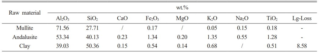
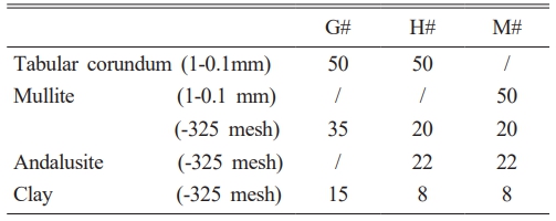
Tabular corundum (Al2O3≥99.5%), mullite, andalusite and clay were used as the raw materials; their chemical compositions were shown in Table 1. Polyvinyl alcohol solution (1:150 wt.%) was used as binder. The experimental formulation was given in Table 2; the prepared specimens were labeled as G#, H# and M#, respectively. The Al2O3 contents in their matrixes were calculated and controlled to be ~60 wt.%. Among them, G# and H# specimens belong to aluminum-silicon system, H# contains andalusite, while G# does not. M# belongs to high-purity mullite system.
The bricks with shape of 25×25×125 mm, and the crucibles with shape of φ60×50mm (inner hole is φ25×32 mm) were made by semi-dry pressure forming (150 MPa). Subsequently, all specimens were dried at 110 ℃ for 24 h and then sintered at 1550-1620 ℃ for 3 h. The porosities of the obtained G#, H# and M# specimens were 20.4%, 19.2% and 18.5%, respectively. The flexural strengths were 19.63 MPa, 20.82 MPa and 20.36 MPa, respectively.
Properties examination
The apparent porosity of the specimens was tested by Archimedes method, the flexural strength was measured by three-point bending method. Static crucible method was used to carry out alkali corrosion test. The crucibles were filled with 30% (vol) Na2CO3 powder, then placed in furnace and treated at 900 ℃ for 1 hour. According to the calculation method described in references [21] and [22], we calculated that the surface tension (s) of Na2CO3 melt is 0.21 N·m-1, the viscosity (η) is 2.28 mPa∙s at 900 ℃. So, it has good fluidity and is suitable for this experiment. After corrosion test, the crucibles were cooled naturally, and then symmetrically cut into two pieces along the centerline. Their appearances were observed visually. The microstructures of the crucibles before and after tests were analyzed by SEM (FEI, INSPECT F50, PHILIPS). X-ray diffractometer (Model D8 ADVANCE, BRUKER, Germany) was used to analyze phase compositions, the scanning range was 5-90°. The high temperature vacuum contact angle measurement system (SCI-1700) was used to measure the contact angles of Na2CO3 melt on refractory during continually rising temperature. The pictures were taken to measure the contact angles of Na2CO3 melt, the obtained value was taken as the instantaneous contact angles at this temperature and to evaluate its wettability.
The appearance of crucibles after corrosion test
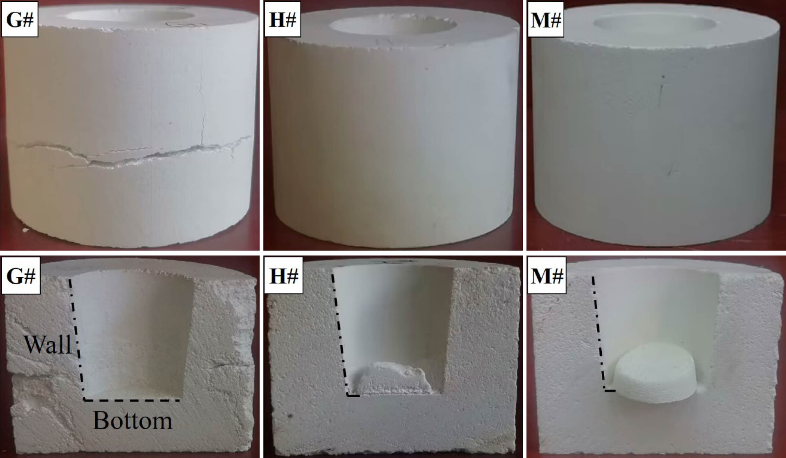
The appearance and longitudinal section of the crucibles after corrosion test are shown in Fig. 1. The G# crucible shows a transverse crack, while the surfaces of the H# and M# crucible are smooth and intact, no cracks are found. The longitudinal sections of the crucibles demonstrate that there is no alkali residue in G# crucible. While a small amount of residue can be seen in the H# crucible, it is attached to the bottom of the inner hole. There is more residue is found in M# crucible, it is not adhered to the bottom and side wall of the crucible (inner surface), and can be taken out easily. According to the residual amount, M# crucible shows the best alkali infiltration resistance, followed by H# crucible, G# crucible is the worst.
Phase analysis
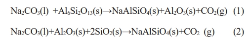
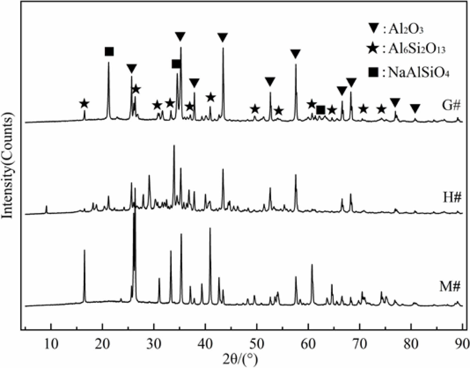
The inner surfaces of the wall and bottom of G#, H# and M# crucibles were scraped by knife (sampling position can be seen in Fig. 1), the acquired powders were characterized by X-ray diffractometer. Their XRD diffraction patterns were shown in Fig. 2. The corundum and mullite can be found in all specimens after indexing. In addition, a sharp nepheline diffraction peak (NaAlSiO4) was found in the XRD patterns of G# sample, indicating that more NaAlSiO4 was produced during the reaction process. The NaAlSiO4 was also found in the XRD patterns of H# sample, but it is weak, indicating that the generated NaAlSiO4 is less. No NaAlSiO4 was also found in the XRD patterns of M# sample. Above analysis indicates that the corrosion reaction is the weakest between Na2CO3 melt and M# specimen, but is the strongest between Na2CO3 melt and G# specimen.
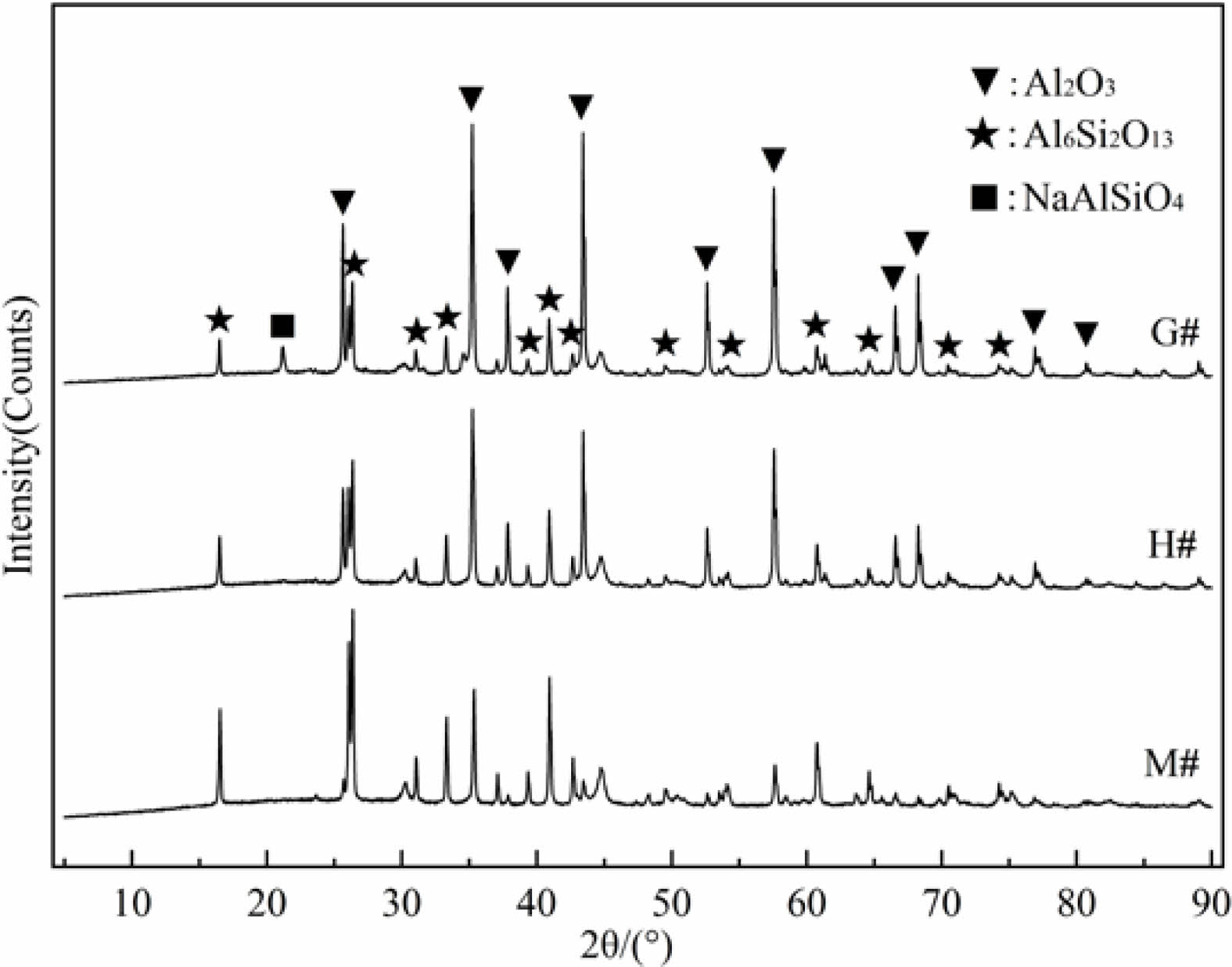
For samples taken from the bottom area (~2 mm down from the bottom interface, named as permeable layer) of G#, H#, and M# crucibles, their XRD patterns are shown in Fig. 3. It displays characteristic diffraction peaks of NaAlSiO4 in the G# crucible, its intensity is weaker than that of the interface layer (as seen in Fig. 2). It indicates that the Na2CO3 melt has infiltrated into the G# crucibles and corrode its interior. While in the H# and M# samples, NaAlSiO4 diffraction peak is hardly visible. It can be concluded that the infiltration and corrosive reaction in H# and M# crucibles are low, especially for M# crucibles. This conclusion is consistent with the analysis of Fig. 1.
Based above XRD analysis, the possible corrosion reactions are shown as the following equations:
Microstructure changes
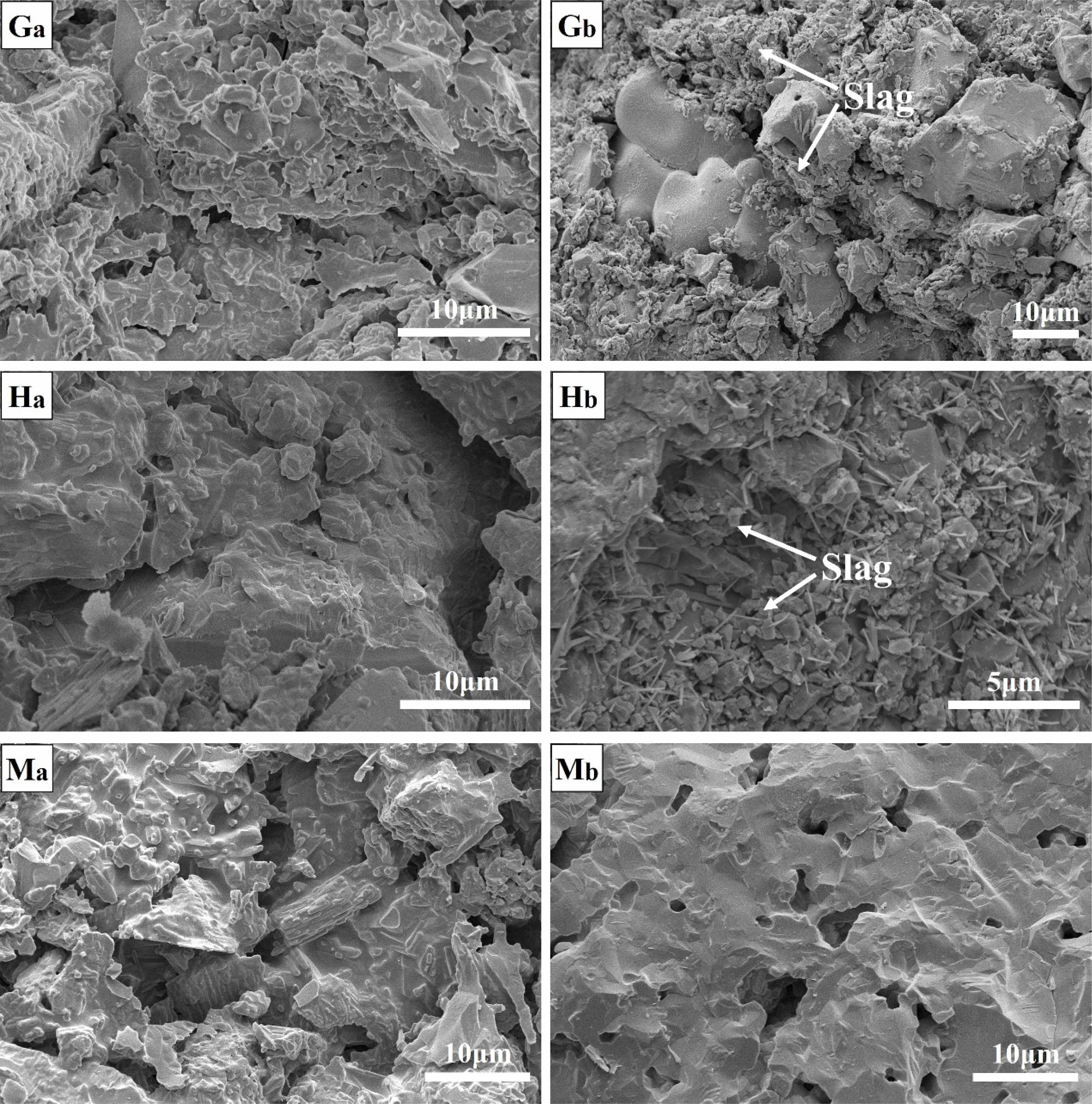
The microstructures of the G#, H# and M# crucible before and after corrosive test were respectively observed. Their micro morphologies were shown in Fig. 4. The observation positions are about 1 mm form the bottom interface of corroded crucibles.
The original brick layer (Ga) of G# crucible is well sintered, there exist a number of irregular pores, most of them are slit, and a few are round holes. The permeable layer (Gb) shows a large number of loose residues, which should be NaAlSiO4 produced from chemical reaction between G# specimen and infiltrated Na2CO3 melt.
The original brick layer (Ha) of H# crucible is also well sintered, there are no obvious pores can be found in matrix. The permeable layer (Hb) shows a small amount of loose residue adhering to the matrix, which should be NaAlSiO4 produced from chemical reaction between H# specimen and infiltrated Na2CO3 melt.
The original brick layer (Ma) of M# crucible has a dense structure, there are a small number of irregular pores. The permeable layer (Mb) shows clear structural profile, some pores are distributed in the matrix, no residues are found. Based on the above analysis, it can be concluded that Na2CO3 melt cannot infiltrate in interior of the M# crucible, so no corrosion product is present.
Based on above analysis, Na2CO3 melt infiltrates into G# crucible significantly, results in more corrosion products; there is a slight infiltration and corrosion reaction in the H# crucible; Na2CO3 melt does not infiltrate into M# crucible.
Analysis
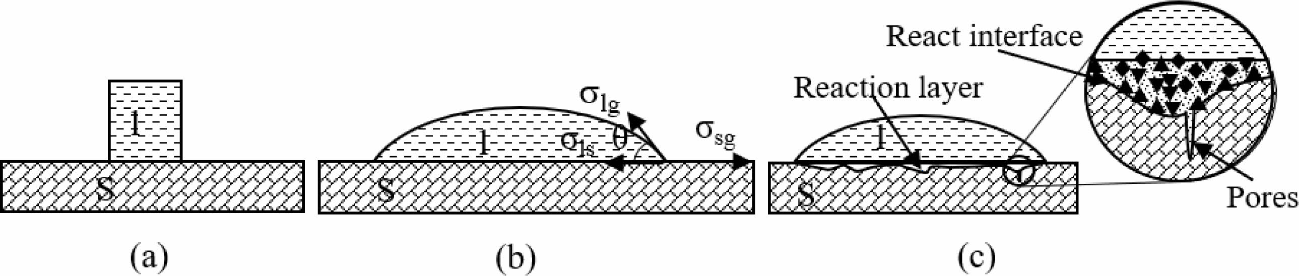
With the increase of temperature, the Na2CO3 on the refractory will undergo a process of melting-wetting-surface corrosion-infiltration-internal corrosion, and finally reaches a stable state. The process can be described as in Fig. 5.
When the NaAlSiO4 was produced during the chemical reaction between Na2CO3 and refractory, its volume expansion is greater than 20% [23, 24]. When the reaction occurs on the surface of the refractory, the damage caused by volume expansion is small, but if it occurs inside the material, it will cause serious damage to the internal structure. The above results have indicated that Na2CO3 melt was easily to infiltrate into the G# crucible and promoted corrosion reaction, the generated NaAlSiO4 results in crucible damage. In contrast, the infiltration of the Na2CO3 melt into the M# and H# crucibles is relatively difficult, and the generated NaAlSiO4 is less, no cracks were found in M# and H# crucibles. So, the damage of crucibles is related to infiltration of Na2CO3 melt, and it can be evaluated by different wetting abilities of G#, H# and M# specimens.
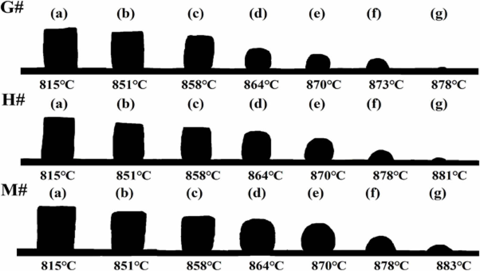
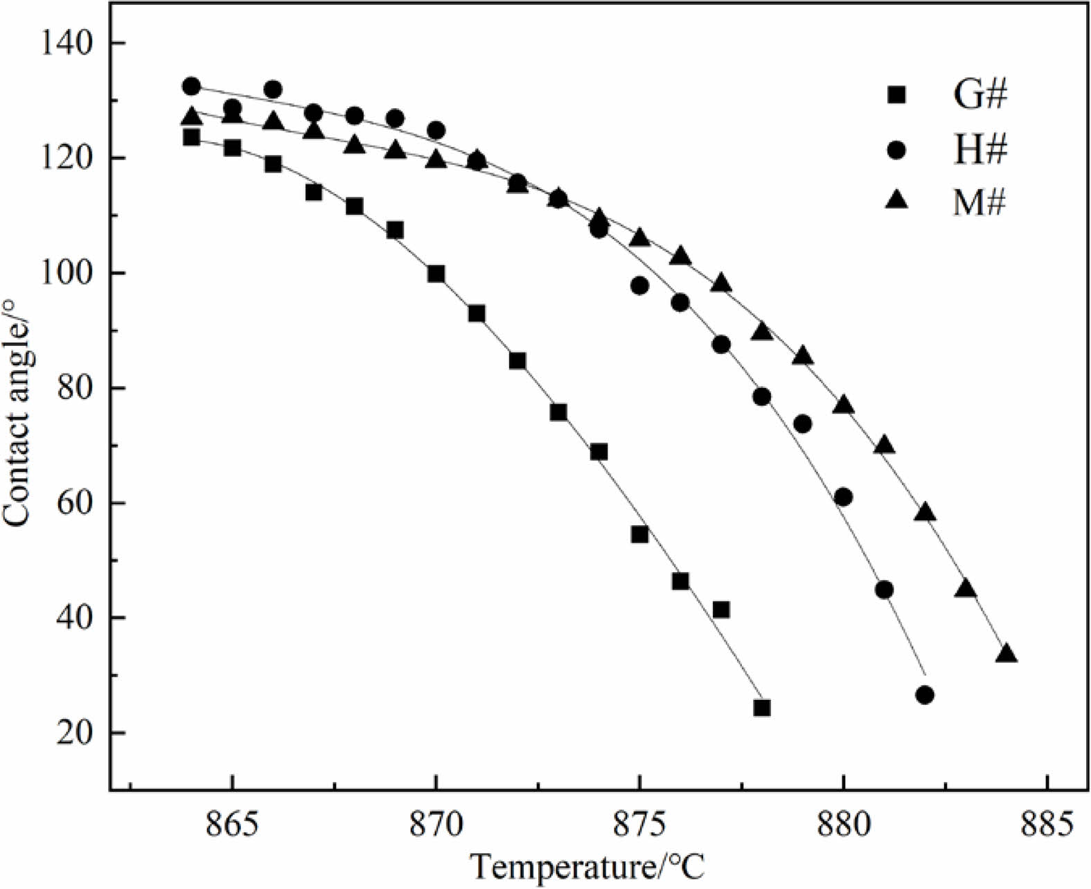
Fig. 6 shows the morphological changes of Na2CO3 cylinder on G#, H# and M# substrate under increasing temperature. It shows that before 851 ℃ (Tm), three Na2CO3 cylinders gradually shrink and deform, they demonstrate similar morphological changes. As the temperature increases above 851 ℃, they begin to melt and quickly change to spherical shape, then spread on refractory substrates. It can be seen that the spreading of Na2CO3 melt is the fastest on G# substrate, but is the slowest on M# substrate. The contact angles calculated based on their shapes, as well as their changes are shown in Fig. 7. At the same temperature, the contact angle of Na2CO3 melt on G# substrate is the smallest; it indicates its wettability is higher. The contact angle of Na2CO3 melt on M# substrates is the largest; it indicates its wettability is the lowest.
The infiltration of Na2CO3 melt into the interior of refractory is related to its wettability. The smaller the contact angle, the greater the wettability, and the easier it is to infiltrate. The infiltration process of Na2CO3 melt along the pores is similar to the capillary phenomenon, and the driving force of the melt infiltration can be evaluated by the adsorption pressure ΔP, as shown in eq. (3).

Where r is the capillary radius, s is the surface tension and the θ is contact angle.
According to the formula (3), it can be calculated that the ratio of the ΔP in G#, H# and M# is about 106:23:1 (assuming pore radius of G#, H# and M# are equal) at 878 ℃, so Na2CO3 melt has greater ability to infiltrate into the G# specimens.
The infiltrating depth and rate of Na2CO3 melt into specimen can be evaluated by formula (4) and formula (5), respectively [25]:
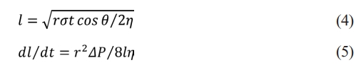
Where l the infiltration depth, η is the liquid viscosity and t is the time.
According to formula (4) and (5), both the infiltration depth and rate of Na2CO3 melt are closely related to the contact angle (θ). Under the conditions of same temperature (T), as the contact angle (θ) decreases, the wettability increases, the depth and rate of infiltration increases. Based on the analysis in Fig. 6 and Fig. 7, it can be concluded that Na2CO3 melt has the largest infiltration depth and the fastest infiltration rate into G# specimen, while the smallest infiltration depth and the slowest infiltration rate into M# specimen.
|
Fig. 1 The appearance and longitudinal section of the crucibles after alkali corrosion experiment. |
|
Fig. 2 XRD patterns of the interface layers of G#, H# and M#. |
|
Fig. 3 XRD patterns of penetration area. |
|
Fig. 4 (a) Original brick layer and (b) permeable layer of the sample. |
|
Fig. 5 Wetting process of Na2CO3 on the refractory during temperature rise. |
|
Fig. 6 Spreading of Na2CO3 melts on G#, H# and M# substrates. |
|
Fig. 7 Contact angles between Na2CO3 melt and different substrates. |
The infiltration of waste liquid into refractory is the main cause of material damage. The wettability of waste liquid on refractory influences its infiltration. They both vary with material systems.
(1) The corundum-mullite system has weak ability to resist the corrosion and infiltration of molten Na2CO3. By contrast, high purity-mullite system has better performance. The mullite transformed from andalusite can improve the infiltration resistance.
(2) The infiltration of molten Na2CO3 into refractory is related to its wetting ability, they both determine the degree of damage to refractory materials.
The authors declare that they have no known competing financial interests or personal relationships that could have appeared to influence the work reported in this paper.
This research has been supported by Natural Science Project of Henan Provincial Department of Education (20B430004) and Zhengzhou Innovation and Entrepreneurship Team Project.
- 1. G. Cheng, Y. Zhao, F. Long, J. Zhang, T. Zhao, L. Liu, X. Wang, and C. Dong, Materials. 13[21] (2020) 4729.
-

- 2. G. Han, Z. Wang, B. Liu, Y. Huang, and S. Su, Ceram. Int. 48[9] (2022) 12395-12407.
-
- 3. N. Li, E. Vainio, L. Hupa, M. Hupa, and E.C. Zabetta, Energy Fuels. 32[12] (2018) 12971-12980.
-
- 4. N.S. Jacobson, K.N. Lee, and T. Yoshio, J. Am. Ceram. Soc. 79[8] (1996) 2161-2167.
-
- 5. Z. Yu, Z. Liu, F. Ye, and L. Xia, Ceram. Int. 48[2] (2022) 2693-2703.
-
- 6. H. Ji, Y. Zhou, Z. He, X. Wu, and B. Dai, Energy Fuels. 35[5] (2021) 3867-3877.
-
- 7. S. He, Q. Feng, B. Duan, G. Chen, Z. Wu, C. Li, and X. Lu, Trans. Nonferrous Met. Soc. China. 32[2] 2022 696-708.
-
- 8. C.W. Andres, M.N. Moline, S. Camelli, and A.G. Tomba Martinez, Ceram. Int. 46[15] (2020) 24495-24503.
-
- 9. Z. Liu, L. Yuan, E. Jin, X. Yang, and J. Yu, Ceram. Int. 45[1] (2019) 718-724.
-
- 10. G. Cheng, T. Zhao, Y. Zhao, T. Jia, Y. Li, X. Wang, and C. Dong, Ceram. Int. 48[4] (2022) 5795-5804.
-
- 11. P. Shen, L. Zhang, Y. Wang, S. Sridhar, Q. Wang, Ceram Int. 42[14] (2016) 16040-16048.
-
- 12. J. Song, Y. Liu, X. Lu, and Z. You, J. Mater. Res. Technol. 9[1] (2020) 314-321.
-
- 13. R. Bai, S. Liu, F. Mao, Y. Zhang, X. Yang, and Z. He, J. Iron Steel Res. Int. 29[7] (2022) 1073-1079.
-
- 14. S. Kim, K. Lee, and Y. Chung, Metall. Mater. Trans. B-Proc. Metall. Mater. Proc. Sci. 47[2] (2016) 1209–1216.
-
- 15. W. Yan, Q. Chen, X. Lin, J. Chen, and N. Li, J. Ceram. Process. Res. 17[4] (2016) 313-317.
-
- 16. W. Yan, J. Chen, N. Li, W. Qiu, J. O-yang, and X. He, J. Ceram. Process. Res. 15[6] (2014) 441-446.
-
- 17. Z. Quan, Z. Wang, H. Liu, Y. Ma, X. Wang, Y. Dong, C. Deng, and G. Fu, Ceram. Int. 48[13] (2022) 18180-18189.
-
- 18. X. Hou, D. Ding, G. Xiao, N. Zhang, X. Chong, J. Luo, E. Jin, Y. Gao, and C. Lei, Ceram. Int. 48[17] (2022) 25103-25110.
-
- 19. J. Chen, N. Li, and W. Yan, J. Eur. Ceram. Soc. 36[6] (2016) 1505-1511.
-
- 20. K. Liu, Q. Guo, X. Fang, A. Raheem, Y. Gong, H. Li, and G. Yu, Ceram. Int. 48[10] (2022) 13869-13879.
-
- 21. J. Li, S. Qi, J. Xu, J. Wang, and W. Weng, Inorg. Chem. Ind. 48[5] (2016) 16-19.
- 22. L. Du, W. Xie, J. Ding, J. Lu, X. Wei, and W. Wang, Int. J. Heat Mass Transf. 131 (2019) 41-51.
-
- 23. C.R. Kennedy, J. Mater. Energy Syst. 3[1] (1981) 27-31.
-
- 24. J. Stjernberg, M. A. Olivas-Ogaz, M.-L. Antti, J.C. Ion, and B. Lindblom, Ceram. Int. 39[1] (2013) 791-800.
-
- 25. W.E. Lee, and S. Zhang, Int. Mater. Rev. 44[3] (1999) 77-104.
-
 This Article
-
2023; 24(6): 1060-1065
Published on Dec 31, 2023
- 10.36410/jcpr.2023.24.6.1060
- Received on Oct 7, 2023
- Revised on Nov 29, 2023
- Accepted on Dec 9, 2023
Services
- Abstract
introduction
experimental procedures
results and discussion
conclusions
- Declaration of Interest
- Acknowledgements
- References
- Full Text PDF
Shared
Correspondence to
- Yi Xia
-
College of Materials Science and Engineering, Henan University of Technology, Zhengzhou 450001, China
Tel : +86 18623719067 Fax: (0371)67756876 - E-mail: Refractories_Lab@163.com
Clean-Energy Research Institute(CRI), Hanyang University, 222, Wangsimni-ro, Seongdong-gu, Seoul, 04763, Korea
E-mail: jcpr@hanyang.ac.kr