


- Study on grinding mechanism and machining technology of Si3N4 ceramic spindle
Songhua Lia,b, Chuang Lia, Minghe Liua, Yonghua Wanga,*, Chuang Zuoa, Hao Zhanga and Yifeng Gaoa
aSchool of Mechanical Engineering, Shenyang Jianzhu University, Shenyang 110168, China
bNational-Local Joint Engineering Laboratory of NC Machining Equipment and Technology of High-Grade Stone, Shenyang 110168, ChinaThis article is an open access article distributed under the terms of the Creative Commons Attribution Non-Commercial License (http://creativecommons.org/licenses/by-nc/4.0) which permits unrestricted non-commercial use, distribution, and reproduction in any medium, provided the original work is properly cited.
In order to improve the machining accuracy of the cylindrical surface of silicon nitride ceramic spindle, the machining technology of the cylindrical surface of ceramic spindle was studied by high-speed universal cylindrical grinder in this experiment. Firstly, the primary and secondary order of the influence of various factors on the surface roughness of ceramic spindle is determined by orthogonal experiment, then the influence law of single grinding parameter on the surface roughness of ceramic spindle is explored by single factor experiment, and the prediction model of the grinding surface roughness value of ceramic spindle is calculated by numerical analysis software, and finally the optimal processing parameters of the cylindrical surface of ceramic spindle are obtained. The experimental results show that the grinding surface roughness of silicon nitride ceramic spindle first decreases and then increases with the increase of grinding wheel linear speed and workpiece linear speed, and then increases with the increase of transverse feed speed and axial feed speed. The relative error between the predicted value of the prediction model and the actual measured value is less than 5%, which shows that the prediction model has a good prediction effect and provides a theoretical basis for actual machining.
Keywords: Silicon nitride ceramic spindle, surface roughness, Roundness and cylindricity, High speed grinding, prediction model.
Due to the excellent characteristics of silicon nitride ceramic materials, such as high hardness, low density, low elastic modulus, low linear expansion coefficient, wear resistance, corrosion resistance and high temperature resistance, more and more precision silicon nitride ceramic products have been specifically applied in the fields of machinery, electronics, chemical industry, military, aerospace and bioengineering [1-3]. Its density is 41% of steel, elastic modulus is 150% of steel, hardness is 200% of steel, and thermal expansion coefficient is 25% of steel [4-6]. Silicon nitride ceramics not only have good mechanical properties, but also have good thermal conductivity, acid and alkali corrosion resistance and so on, and are recognized as the ceramic materials with the best comprehensive properties in the 21st century [7-9]. The application of silicon nitride ceramic spindle in high-speed motorized spindle will greatly improve the comprehensive performance of motorized spindle. Compared with traditional steel materials, ceramic spindle and bearing produce less centrifugal force and heat when rotating at high speed, which can greatly improve the working performance of high-speed motorized spindle and make it have higher speed and greater torque, and is the best material for motorized spindle [10].
In recent years, many scholars at home and abroad have conducted in-depth research and analysis on the surface grinding technology of hard and brittle materials such as silicon nitride. Lu et al. [11, 12] deeply studied the grinding technology of zirconia ceramic spindle, focusing on the surface roughness, roundness and cylindricity of the spindle, thus improving the surface quality and shape and position accuracy of zirconia ceramic spindle. Liu et al. [13] optimized the grinding process by studying the surface cracks of engineering materials, and constructed the fracture model of ceramic materials. Agarwal et al. [14] studied the factors affecting the grinding surface quality through the grinding experiment of silicon carbide ceramics, and carried out multi-objective optimization of ceramic grinding process through genetic algorithm. Chen et al. [15] established a theoretical model of surface formation in high-speed grinding of ceramic materials, analyzed the influence of grinding parameters on surface quality, and realized ultra-precision grinding of ceramic materials by optimizing grinding process. Sun et al. [16] studied the removal mechanism of high-speed grinding of Si3N4 ceramics, and proposed that the grinding force could be reduced by increasing the speed of grinding wheel or reducing the grinding depth. Zhang et al. [17, 18] used laser-assisted machining of Si3N4 ceramics. Compared with conventional grinding methods, the grinding force and grinding temperature during laser-assisted machining were significantly reduced, and the tool durability was improved, but the roughness was less affected. Wu et al. [19] carried out high-speed grinding of silicon carbide ceramics, and through the method of combining simulation and experiment, it was proposed that selecting a larger grinding wheel speed and appropriate chip thickness could improve the surface quality of the workpiece and improve the grinding efficiency. Li [20] and others put forward multi-step high-speed grinding technology to improve the surface quality and grinding efficiency of glass-ceramics after grinding, and obtained the best combination of grinding process parameters through experiments. Yan et al. [21] analyzed the surface roughness, surface morphology and subsurface damage of Si3N4 ceramics by internal grinding, and established a prediction model of internal grinding of Si3N4 ceramics. Choudhary [22] and others have greatly improved the machining accuracy of the workpiece by increasing the linear speed of the grinding wheel and then reducing the chip thickness in order to control the surface defects of advanced ceramics during high-speed grinding. Yang et al. [23] used ultra-short pulse laser to process ZrO2 ceramics, revealed the mechanism of ultra-short pulse laser processing of ZrO2 ceramics, and proposed that with the increase of laser energy density, the material removal efficiency first increased and then decreased, and the surface roughness first decreased and then increased, which provided guidance for ultra-short pulse laser processing of ZrO2 ceramics.
At present, the main reason that restricts the wide application of silicon nitride ceramic spindle is the high processing cost, in which the grinding cost accounts for more than 80% of the total processing cost. On the other hand, due to the hard and brittle characteristics of ceramics, it becomes a typical difficult-to-machine material, so the research on its machining mechanism and technology is far less extensive and in-depth than that of metal materials [24, 25]. In order to obtain high-efficiency and high-quality grinding technology for the excircle of silicon nitride ceramic spindle, a large number of grinding process experiments were carried out by changing the process parameters such as grinding wheel linear speed, transverse feed speed, axial feed speed and workpiece linear speed, and the influence law of the above process parameters on surface quality was analyzed, which provided certain reference value for rational selection of grinding parameters.
The experimental equipment
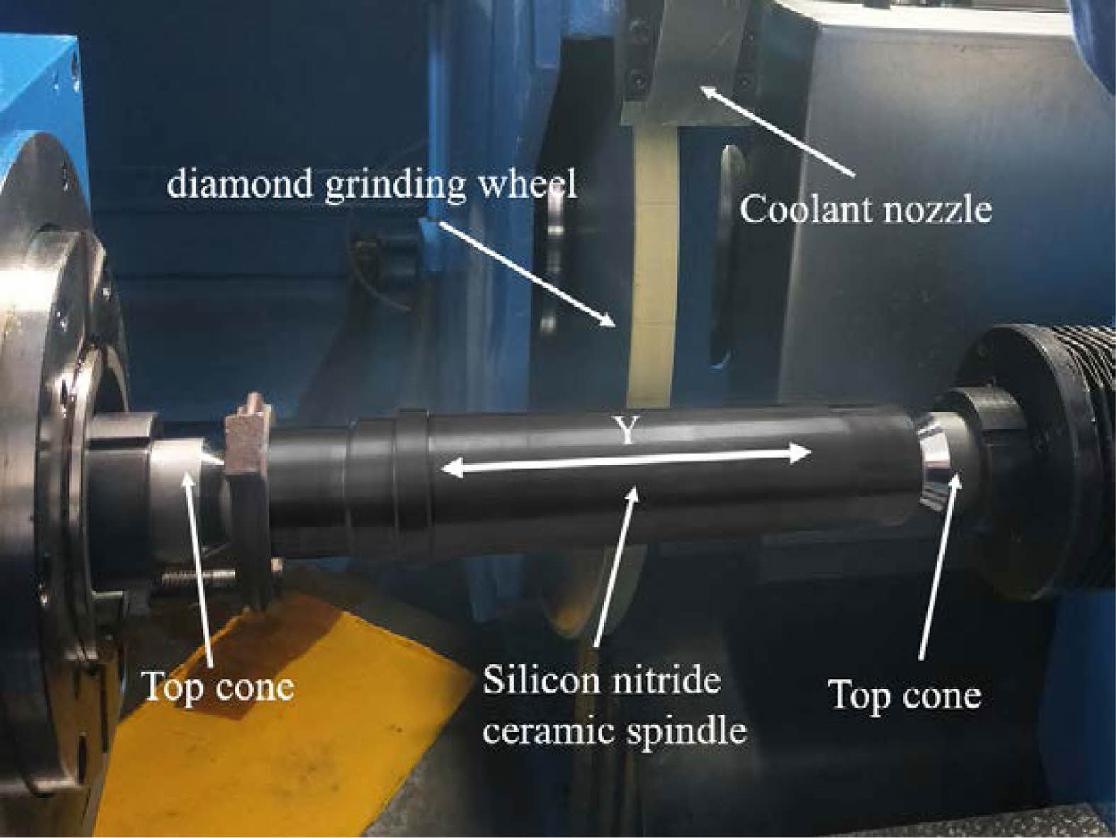
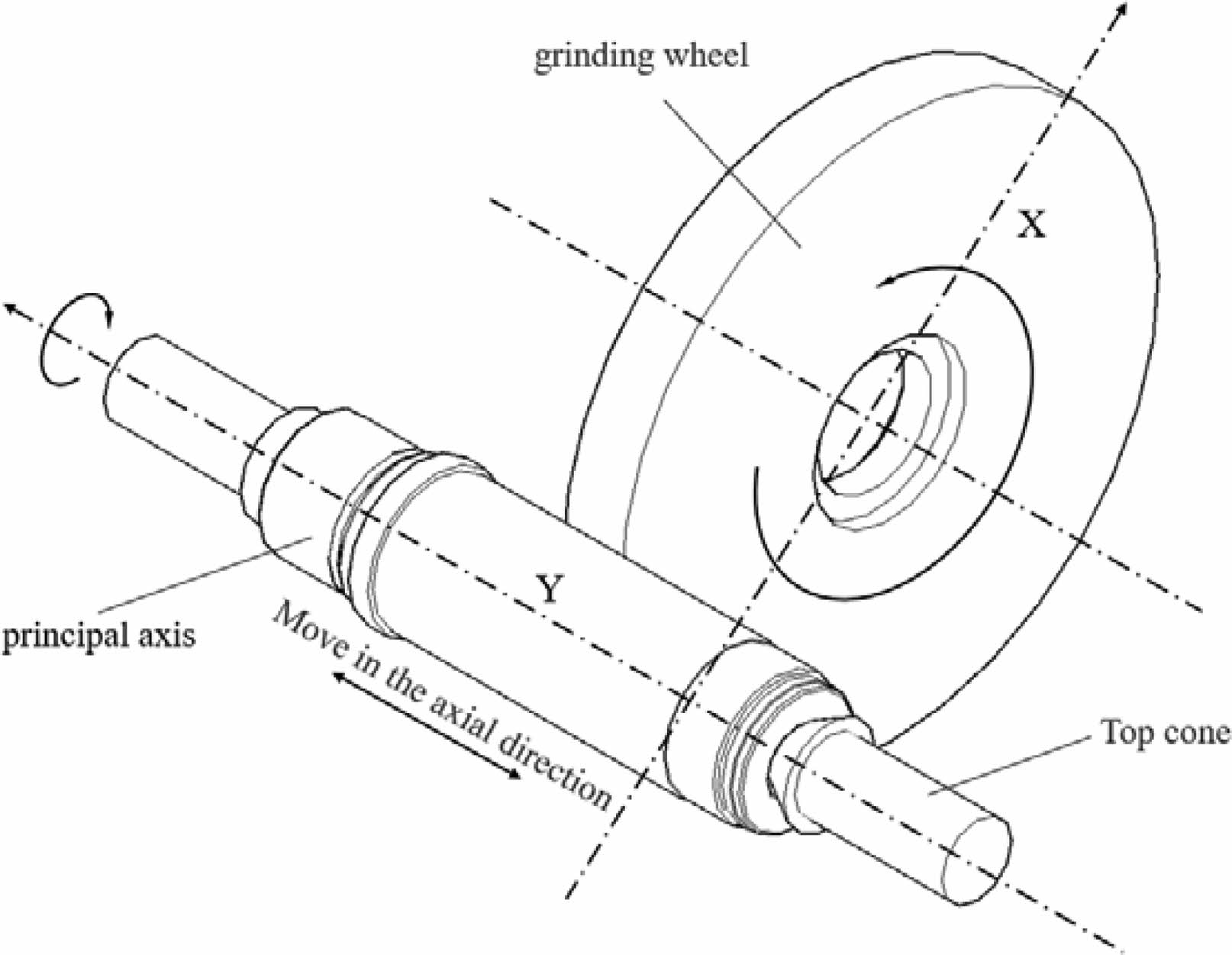
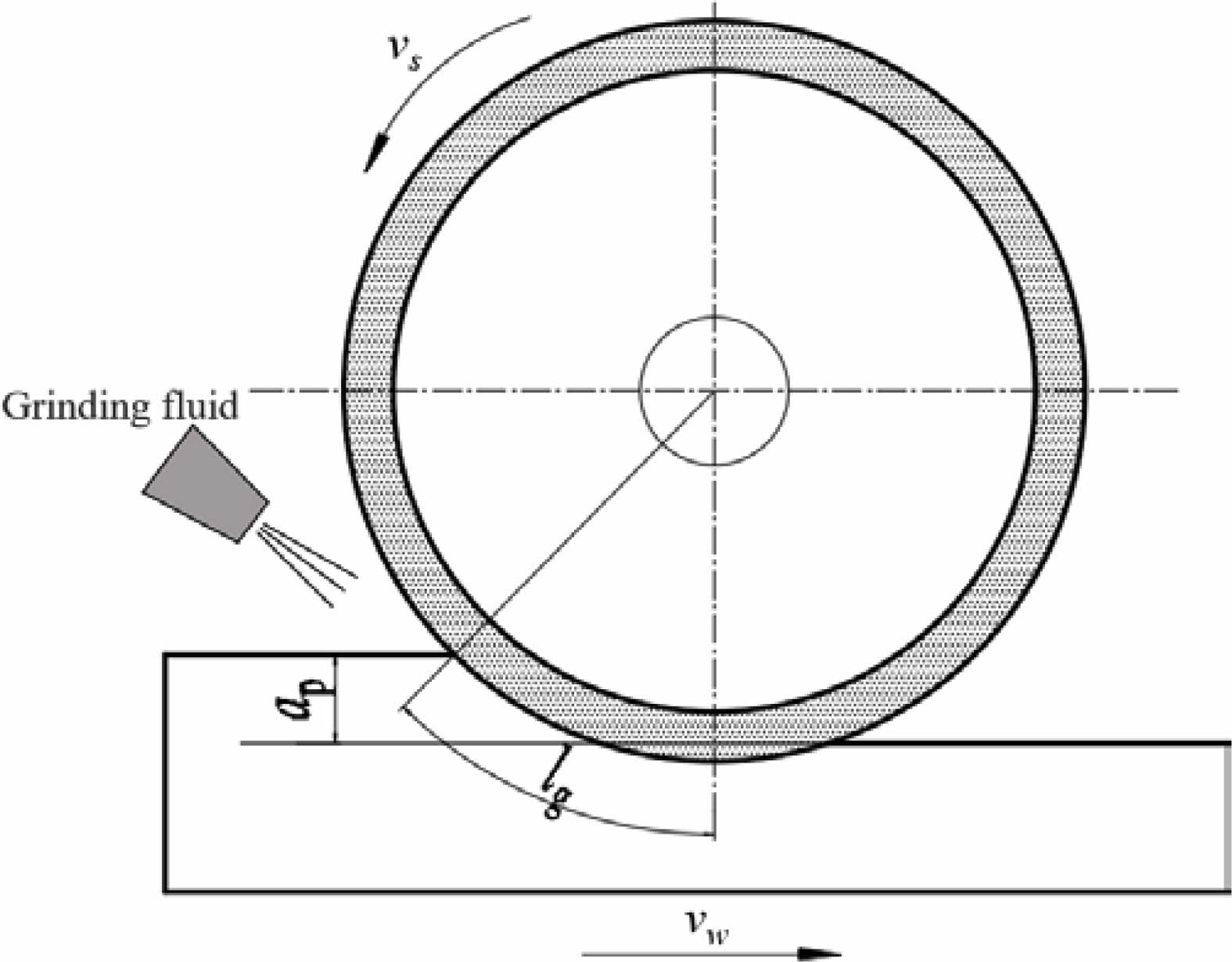
MGKS1432-H CNC high-precision ultra-high-speed universal cylindrical grinder is used in the experiment. In order to improve the grinding efficiency, the longitudinal grinding method is adopted in this experiment, and the experimental process is shown in Fig. 1. The power of the grinder spindle is 18 kw, the maximum speed is 7160 r/min, the machining accuracy is 1 μm, and SBS dynamic balance instrument is built in. The clamping mode of the silicon nitride ceramic spindle is positioned by the top cone, and the dial drives the spindle to rotate, and the spindle moves axially in the Y direction during machining. The feeding mode of the equipment and the movement relationship between the workpiece and the grinding wheel are shown in Fig. 2.
The experimental materials
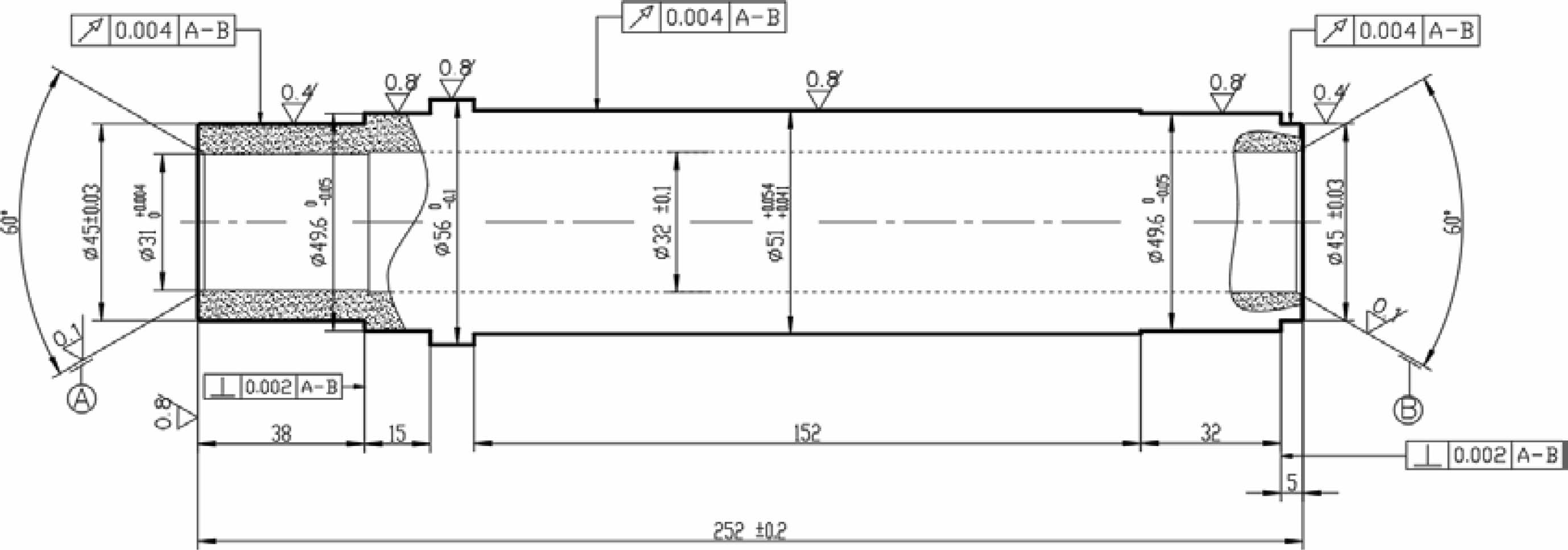
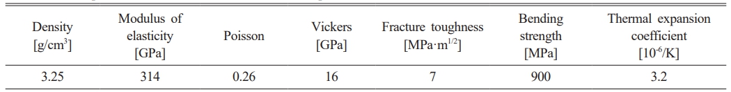
In this experiment, Si3N4 ceramic spindle blank is selected as grinding specimen, and its main material properties are shown in Table 1. Fig. 3 shows the machining requirements of the silicon nitride ceramic spindle designed by the laboratory, and its dimensional accuracy is shown in the figure. Because the ceramic bonded diamond grinding wheel has high strength and wear resistance, and it is not easy to heat up and block during grinding, the ceramic bonded diamond grinding wheel is used to grind the silicon nitride ceramic spindle in this experiment. The ceramic bond diamond grinding wheel selected in the experiment is formed by pressing and sintering diamond and ceramic bond. The smaller the grain size of the grinding wheel, the lower its grinding ability. In this experiment, the machining allowance of Si3N4 ceramic spindle blank should be removed, so it is not suitable to use a smaller grain size grinding wheel, and then the grain size of the grinding wheel is selected as 140/170. The basic parameters of the ceramic bond diamond grinding wheel are shown in Table 2.
The experimental scheme
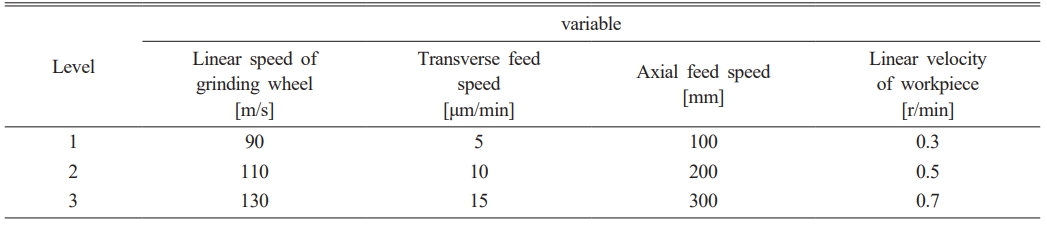
Under the condition that the grinding wheel model is determined, the processing parameters that affect the grinding surface quality of the cylindrical surface of the ceramic spindle are mainly the linear speed of the grinding wheel, the axial feed speed, the transverse feed speed and the linear speed of the workpiece. According to the statistical simulation method, in order to obtain the expected value of surface roughness, the numerical characteristics of surface roughness value are obtained by controlling variables, and the influence of different machining parameters on the surface quality of Si3N4 workpiece is deeply discussed. Therefore, the variable control and level of this experiment are shown in Table 3. As shown in Table 3, three levels of grinding wheel linear speed, transverse feed speed, axial feed speed and workpiece linear speed are respectively subjected to one-to-one cross experiments, and there are 9 groups of experiments. In the experiment, the total removal of Si3N4 workpiece is 50 μm, and the surface to be machined will be ground with different machining parameters in each experiment.
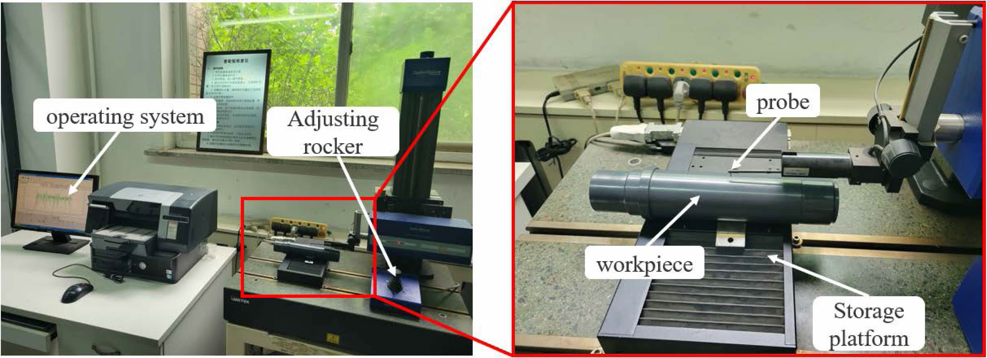
After machining, Taylor Hobson roughness tester is used to measure the surface roughness. The measuring method of this equipment is that the probe touches the measured surface to obtain the signal, and the signal is processed and analyzed by Ultra software, and its detection accuracy can reach 0.001 μm at the highest. As shown in Fig. 4, the movement direction of the equipment is consistent with the axial direction of the ceramic spindle during measurement, and the sampling length for each measurement is 2.5 mm. In order to increase the number of samples and reduce the random error, seven measuring positions are selected for each excircle, and a highest value and a lowest value are removed, and the remaining five values are averaged.
|
Fig. 1 Grinding experiment of silicon nitride ceramic spindle. |
|
Fig. 2 Schematic diagram of grinding process. |
|
Fig. 3 Processing requirements of silicon nitride ceramic spindle. |
|
Fig. 4 Measuring surface roughness with Taylor Hobson roughness tester. |

Analysis of orthogonal experiment results
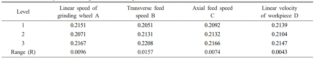
According to the variables and levels listed in Table 3, the linear speed of grinding wheel is set as variable A, the transverse feed speed is set as variable B, the axial feed speed is set as c, and the workpiece rotation speed is set as d, and the surface roughness value Ra is measured, and the corresponding relationship between the variables and the roughness is obtained. According to the experimental arrangement, the nine groups of experiments can be regarded as orthogonal experiments with four factors and three levels. According to the results of orthogonal experiment, the Range intuitive analysis table of surface roughness value Ra is established, as shown in Table 4.
As can be seen from Table 4, with the increase of grinding wheel linear speed and workpiece linear speed, the surface roughness first decreases and then increases. With the increase of transverse feed speed and axial feed speed, the surface roughness shows an upward trend. The influence degree of each factor on the surface roughness can be compared by the magnitude of the extreme difference in Table 4. The greater the extreme difference, the greater the influence degree. The experimental results show that in the experiment of grinding the cylindrical surface of Si3N4 ceramic spindle, the transverse feed speed has the greatest influence on the surface roughness, followed by the grinding wheel linear speed, followed by the axial feed speed, and the linear speed of the workpiece has no obvious influence on the surface roughness.
Influence of linear speed of grinding wheel on surface quality
The essence of grinding is the accumulation of micro-cutting action between a large number of abrasive particles distributed on the surface of high-speed rotating grinding wheel and the surface of workpiece. The relative speed between grinding wheel and workpiece is one of the important basic parameters to correctly understand the grinding process, especially it has an important influence on grinding temperature and grinding surface quality [26]. The research of Bifano et al. [27] shows that the m aterial removal mode of grinding surface is mainly brittle fracture or plastic removal, which is determined by the relationship between the maximum undeformed cutting thickness hmax and the critical cutting depth dc of ductile removal. When hmax < dc, the silicon nitride ceramics are mainly removed by plastic, and the grinding surface texture is relatively smooth, which realizes the ductile domain grinding of silicon nitride ceramics; When hmax > dc, brittle fracture is the main way to remove grinding surface materials, and the surface quality is relatively poor. Therefore, in the process of exploring the influence of grinding wheel linear speed on the surface roughness of silicon nitride ceramics, the maximum undeformed cutting thickness hmax and dc are introduced, and their expressions are as follows:
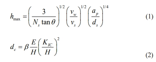
Formula: Ns is the effective number of abrasive particles that the grinding wheel surface participates in grinding; θ is the wrap angle of abrasive particles, usually θ = 60; Vw is the linear velocity of the workpiece; Vs is the linear speed of grinding wheel; ds is the grinding wheel diameter; αp is grinding depth, αp = vf/nw, where vf is feed speed and nw is workpiece rotation speed; β is the processing condition coefficient, and grinding β = 0.15; E is the elastic modulus of the material; H is the hardness of the material; KIC is the fracture toughness of the material.
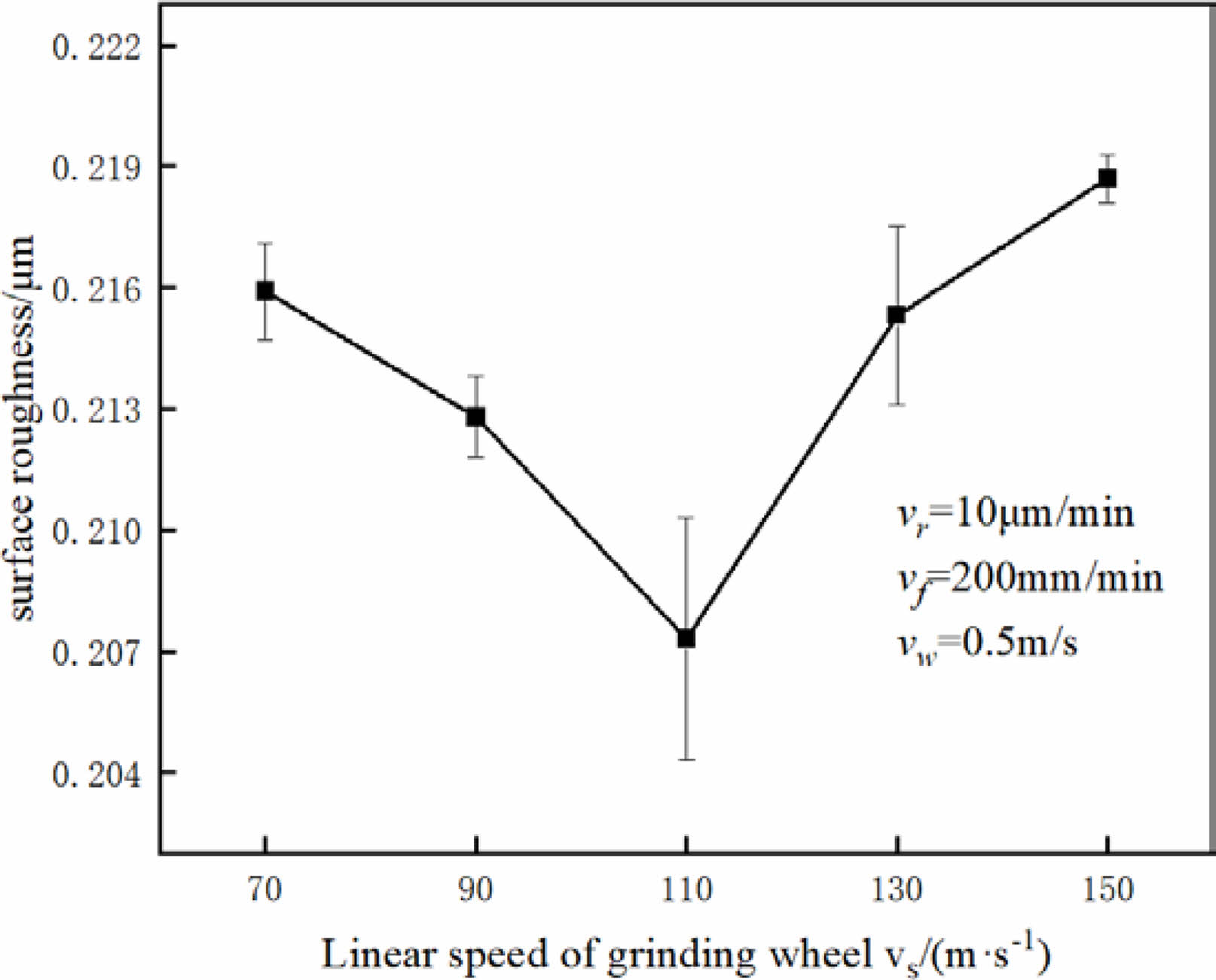
In the single factor experiment of grinding wheel linear speed, the transverse feed speed is 10 μm/min, the axial feed speed is 200 mm/min, and the workpiece linear speed is 0.5 m/s. The variation trend of roughness Ra with the increase of grinding wheel linear speed is shown in Fig. 5. As can be seen from Fig. 5, Ra decreases with the increase of grinding wheel linear speed, and the roughness value Ra reaches the minimum when the grinding wheel linear speed is 110 m/s. However, with the continuous increase of the linear speed of the grinding wheel, the roughness value Ra shows a gradual increase trend, and the increase is more and more obvious.
According to formula (1), with the increase of grinding wheel linear velocity vs, the maximum undeformed cutting thickness hmax of Si3N4 material decreases, the grinding force of a single diamond particle decreases, the specific grinding energy increases, and the proportion of plastic removal in silicon nitride grinding increases, so the surface roughness Ra of silicon nitride ceramic spindle decreases with the increase of grinding wheel linear velocity [28]. However, when the linear speed of the grinding wheel exceeds 110 m/s, the rotating speed of the machine tool spindle approaches its vibration frequency, which leads to the increase of the vibration of the grinding wheel, the deepening of the scratches on the surface of the ceramic spindle and the decline of the surface quality. On the other hand, the abrasive dust will increase in the process of high-speed grinding, which will block the grains of diamond grinding wheel and passivate the grains, resulting in poor surface quality. It can be seen that better surface quality of workpiece can be obtained by properly increasing the linear speed of grinding wheel.
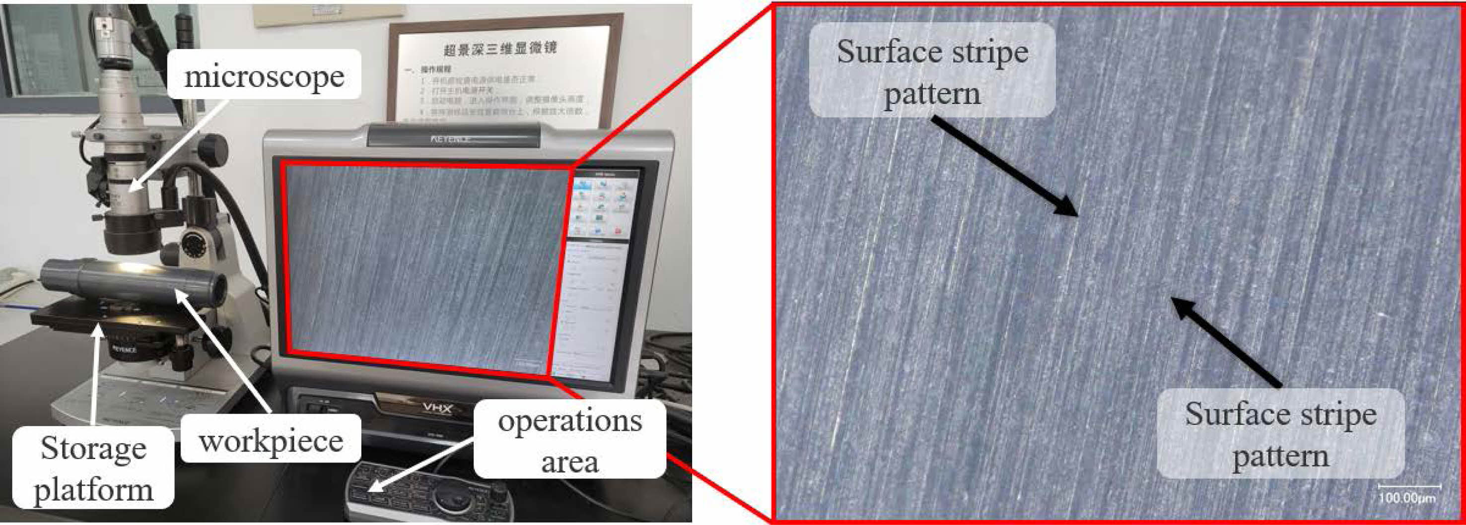
After machining, the surface morphology of silicon nitride ceramic spindle was observed by VHX-1000 three-dimensional microscope with super depth of field. The equipment can observe the surface morphology at 100 times to 1000 times, and its highest resolution reaches 54 million pixels. It can be observed from Fig. 6 that the machined surface of the ceramic spindle is striped. When the linear speed of the grinding wheel is 90 m/s, 110 m/s and 130 m/s, the depth-of-field diagram of the main shaft surface of silicon nitride ceramics is shown in Fig. 7. It can be observed in Fig. 7(a) that when the linear speed of the grinding wheel is 90 m/s, the wear marks on the surface of silicon nitride ceramics are shallow. Comparing Fig. 7(b) with Fig. 7(a), it can be seen that when the linear speed of grinding wheel is increased from 90 m/s to 110 m/s, the scratches on the surface of ceramic spindle are reduced and the surface becomes smooth. However, with the increase of the linear speed of the grinding wheel, the proportion of plastic removal gradually decreases, and the brittle fracture area of silicon nitride ceramics increases, which leads to the deterioration of the surface quality of the ceramic spindle and the deep scratches on the surface of the ceramic spindle, as shown in Fig. 7(c).
Influence of transverse feed speed on surface quality
In the precision grinding technology, there are countless factors affecting the surface roughness Ra of the workpiece. Abrasive properties, grinding wheel models, grinding parameters, cooling conditions and surface material removal methods all have certain influences on the surface roughness Ra of the workpiece. As shown in Fig. 8, the grinding wheel and the workpiece are assumed to be two absolute rigid bodies in this model, that is, the influence of the elastic deformation of the workpiece or the grinding wheel on the contact arc length is ignored, and then the expression of the geometric contact arc length lg between the grinding wheel and the workpiece is derived by geometric method, namely:
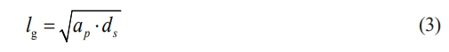
Formula: αp is grinding depth; ds is the grinding wheel diameter.
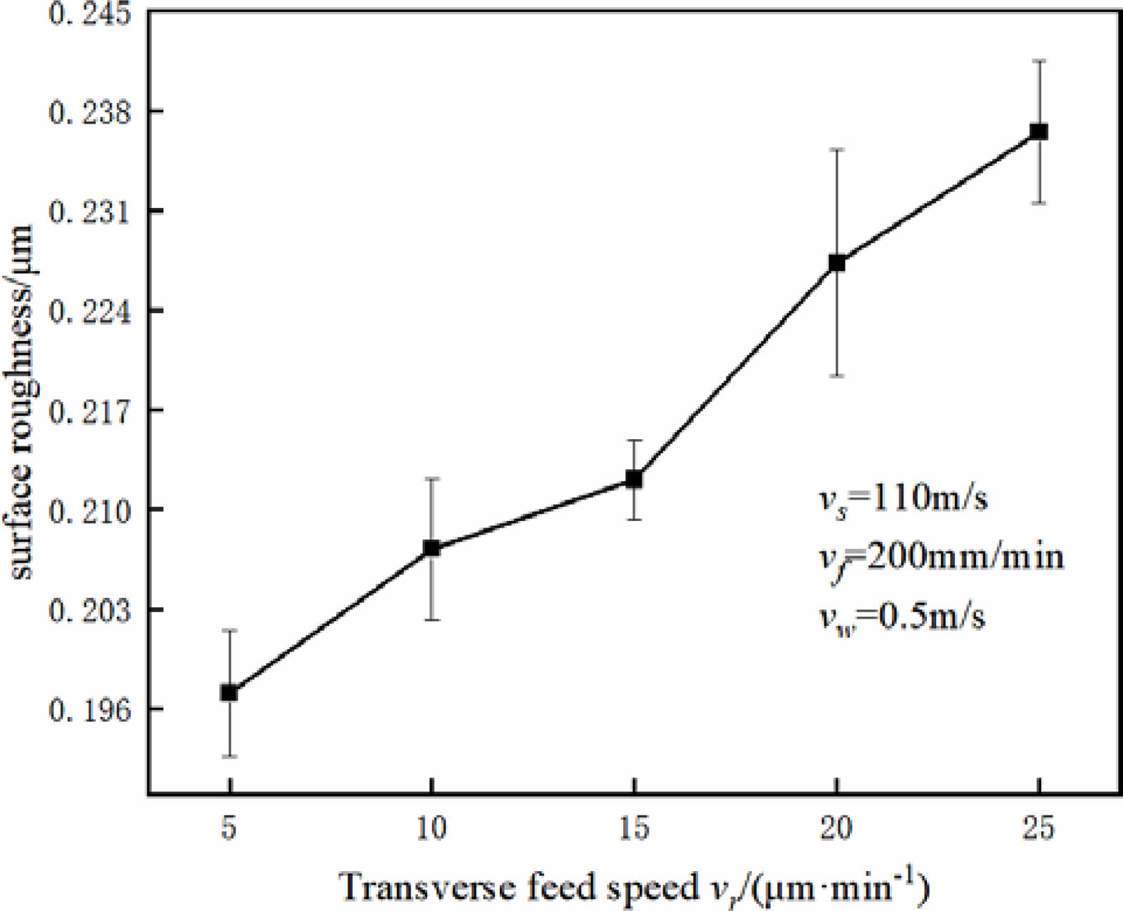
In the single factor experiment of transverse feed speed, the linear speed of grinding wheel is 110 m/s, the axial feed speed is 200 mm/min, and the linear speed of workpiece is 0.5 m/s. The variation trend of surface roughness Ra with the increase of transverse feed speed is shown in Fig. 9. As can be seen from Fig. 9, the surface roughness Ra shows an upward trend with the increase of the transverse feed speed.
According to Formula (3), with the increase of the transverse feed speed vr, the contact arc length between the grinding wheel and the workpiece increases in unit time, and the grinding contact area increases, which makes it difficult to discharge the abrasive chips in time, which makes the grinding and the surface of the ceramic spindle of the workpiece scratch each other, thus causing the surface quality of the ceramic spindle to deteriorate; With the increase of transverse feed speed, the maximum undeformed chip thickness of abrasive particle removal increases, and the proportion of brittle removal of silicon nitride ceramics increases, which increases the surface roughness of ceramic spindle [29].
Influence of axial feed on surface quality
When grinding the surface of ceramic materials, there are many factors that affect its surface quality, such as different grinding methods, different types, particle sizes and concentrations of grinding wheels, different types and flow rates of grinding fluids, and different grinding process parameters selected during grinding. The changes of these factors will change the temperature of ceramic materials during grinding, thus affecting the surface quality of ceramic materials after grinding. Therefore, in the process of exploring the influence of axial feed speed on the surface roughness of silicon nitride ceramics, Rowe temperature rise model [30] is introduced, and the expression of its maximum temperature rise ΔT is:
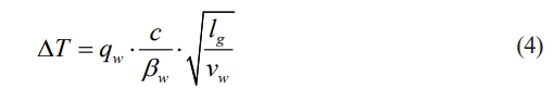
Formula: qw is the heat flowing into the workpiece; c is the heat transfer coefficient, and most shallow grinding takes c = 1; βw is the thermal contact coefficient of ceramic materials; lg is the grinding contact arc length.
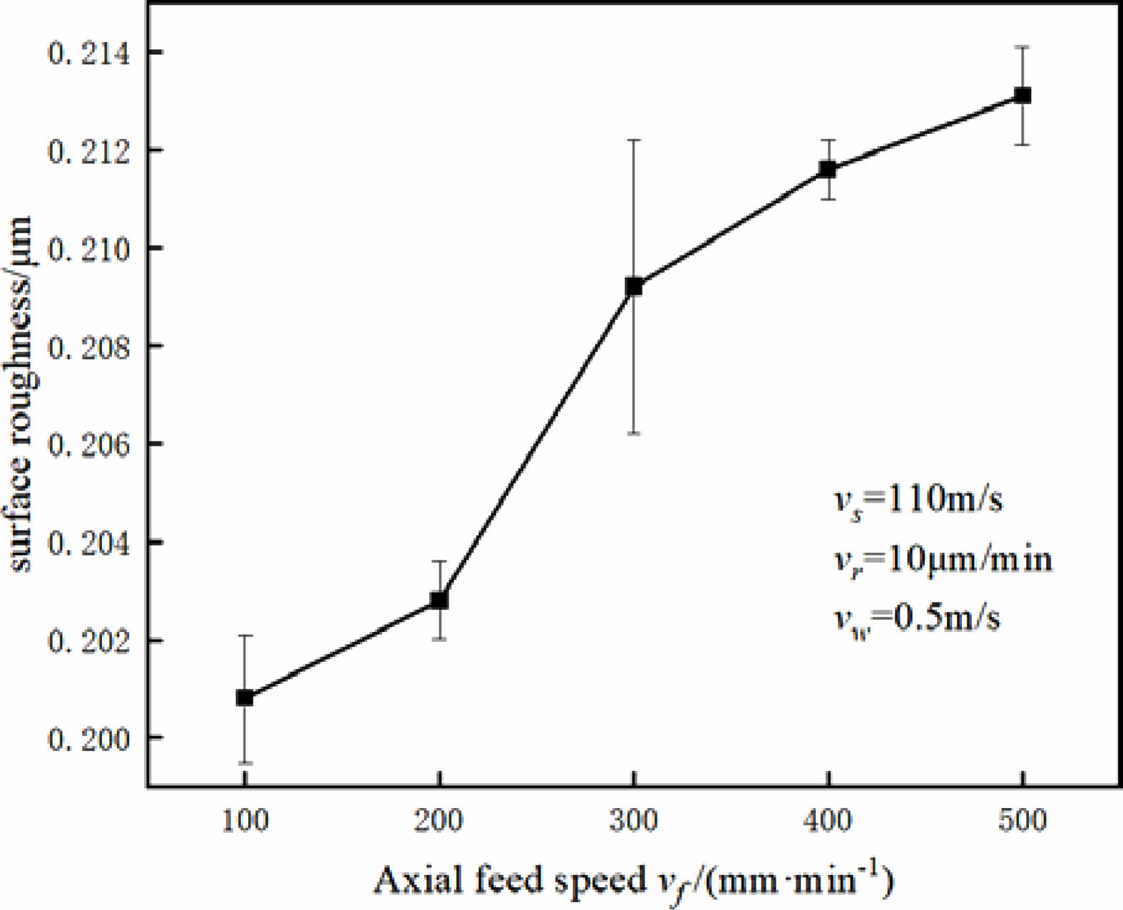
In the single-factor experiment of axial feed speed, the linear speed of grinding wheel is 110 m/s, the transverse feed speed is 10 μm/min, and the linear speed of workpiece is 0.5 m/s. The variation trend of roughness Ra with the increase of axial feed speed is shown in Fig. 10. As can be seen from Fig. 10, with the increase of axial feed speed, the surface roughness Ra gradually increases, especially in the low feed speed range, the surface roughness changes obviously.
According to formula (4), as the axial feed speed vf increases, the contact arc length between the grinding wheel and the grinding area of the ceramic spindle increases, thus increasing the maximum temperature rise ΔT on the surface of the ceramic spindle. However, excessive temperature will deteriorate the surface quality of the silicon nitride ceramic spindle, accompanied by surface cracks, resulting in an increase in surface roughness Ra [31].
Influence of linear velocity of workpiece on surface quality
Because the fracture strength of ceramic materials is influenced by grinding parameters, grinding force, grinding surface texture and residual stress, the variation law of ceramic materials in grinding process is complicated. When discussing the influence of linear velocity of workpiece on the surface quality of silicon nitride ceramic spindle, a single abrasive particle is introduced to remove the volume of material. Assuming that the abrasive head is conical, the chip shape can be approximately regarded as a quadrangular pyramid, and the cutting depth of a single abrasive particle is h, then the maximum chip cross-sectional area is h2·tanθ, and the volume expression of the material removed by a single abrasive particle is:
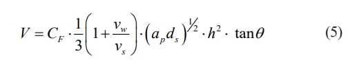
Formula: CF is the compensation coefficient of cutting path; ds is the grinding wheel diameter; θ is the top half angle of the effective abrasive cone; h is the cutting depth of a single abrasive particle; vw is the workpiece feed speed; vs is the grinding wheel linear speed; ap is the grinding depth.
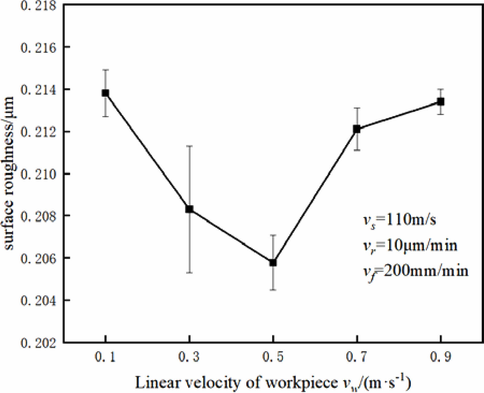
In the single factor experiment of workpiece linear speed, the variation trend of surface roughness Ra with the increase of workpiece linear speed is shown in Fig. 11, when the grinding wheel linear speed is 110 m/s, the transverse feed speed is 10 μm/min and the axial feed speed is 200 mm/min. As can be seen from Fig. 11, Ra decreases with the increase of the linear speed of the workpiece, and the roughness value Ra reaches the minimum when the linear speed of the workpiece is 0.5 m/s. However, with the continuous increase of the linear speed of the workpiece, the roughness value Ra shows a gradual increase trend, and the increase is more obvious.
This is because when the linear velocity vw of the workpiece is small, the tangential grinding force of the grinding wheel is small, the friction heat between the grinding wheel and the workpiece is less, and the temperature in the grinding zone is lower. With the increase of workpiece feed speed and tangential grinding force, the temperature rise increases, the proportion of plastic removal increases and the surface roughness decreases. However, when the linear speed of the workpiece exceeds 0.5 m/s, it can be seen from Formula (5) that too high linear speed of the workpiece will lead to the increase of the volume of the material removed by a single abrasive particle, which will lead to the increase of the tangential grinding force of the grinding wheel, and the greater grinding force will lead to cracks on the surface of the ceramic spindle, which will lead to the deterioration of the surface quality of the ceramic spindle [32]. It can be seen that better surface quality can be obtained by properly increasing the linear speed of the workpiece.
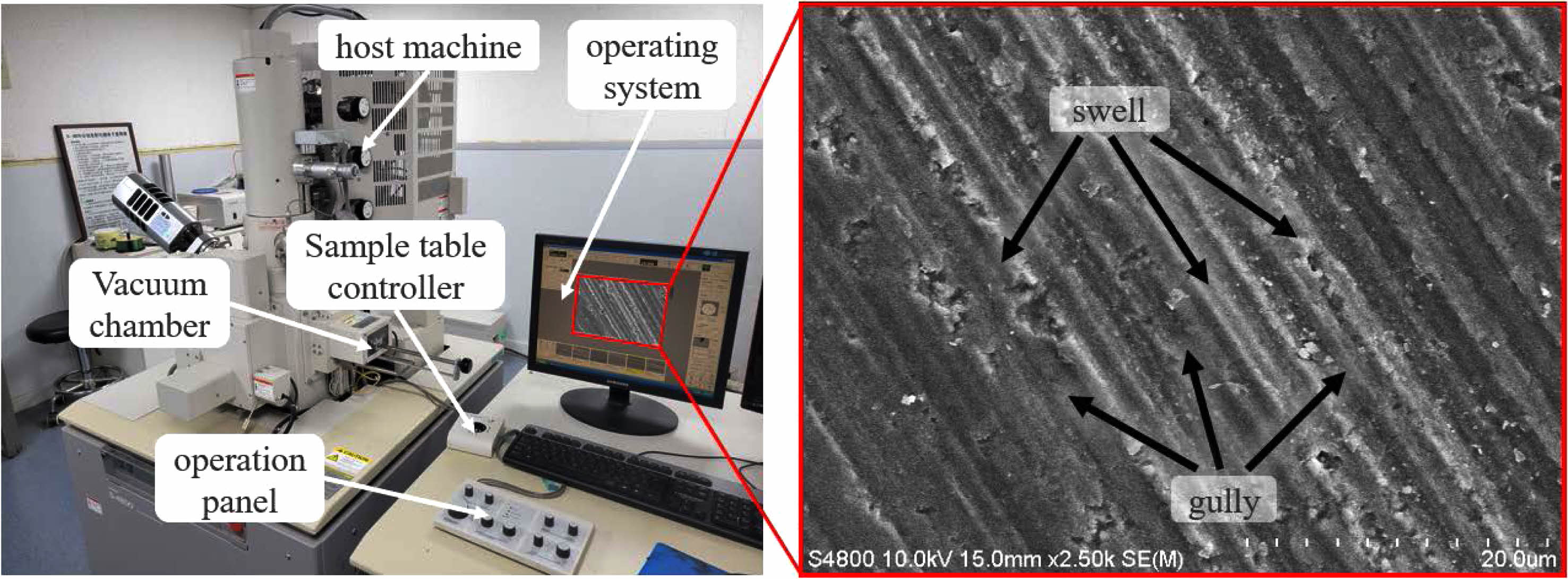
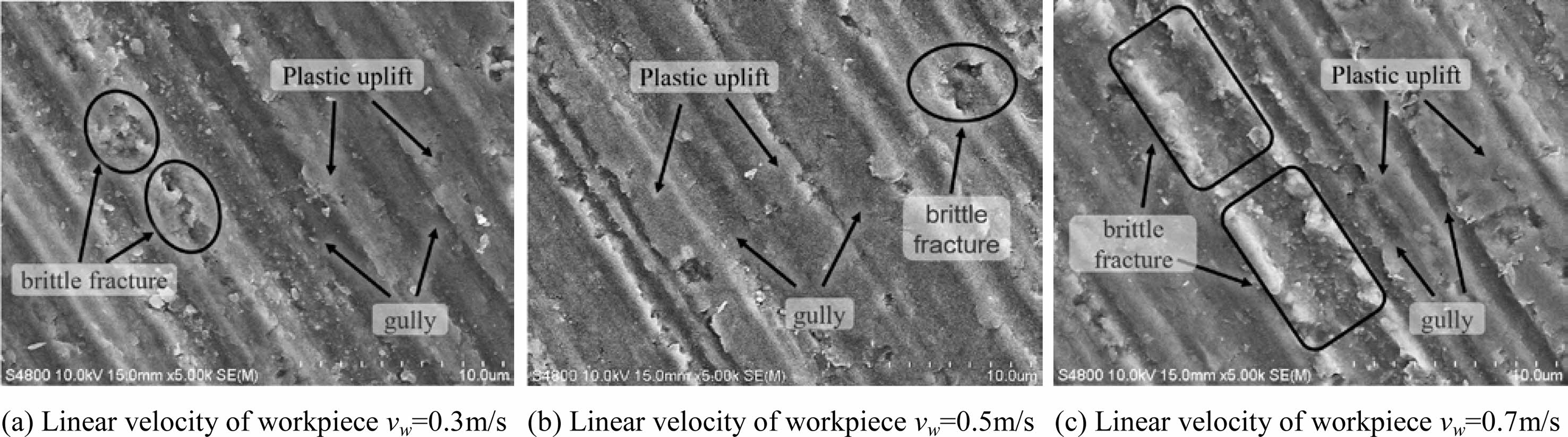
After the machining, Hitachi S-4800 scanning electron microscope was used to observe the surface morphology of the cylindrical surface of the main shaft of silicon nitride ceramics. The equipment can observe the surface morphology of the workpiece between 20 times and 800,000 times. Because of the insulating properties of silicon nitride ceramics, it is necessary to spray gold on silicon nitride ceramics in advance. As can be seen from Fig. 12, the surface after machining will have bumps and gullies as shown in the figure. When the linear velocity of the workpiece is 0.3, 0.5 and 0.7 m/s, the scanning electron microscope image of the spindle surface of silicon nitride ceramics is shown in Fig. 13. From Fig. 13, it can be seen that in the process of removing silicon nitride ceramics, plastic bumps, gullies and brittle fractures will appear on the machined surface, and the surface quality will be better when the plastic removal ratio is large. When the linear velocity of the workpiece is 0.3 m/s, there are more brittle fractures and less plastic bulges on the surface of silicon nitride ceramics, as shown in Fig. 13(a). When the linear speed of the workpiece increases to 0.5 m/s, the proportion of plastic removal increases gradually, and the plastic raised area of silicon nitride ceramics increases, which leads to the improvement of the surface quality of the ceramic spindle, as shown in Fig. 13(b); Continuing to increase the linear speed of the workpiece to 0.7 m/s leads to an obvious increase in brittle fracture and a deterioration in the surface quality of the workpiece, as shown in Fig. 13(c).
Experimental results and analysis of roundness and cylindricity
The design goal of high-speed precision motorized spindle requires high rigidity, high precision, good vibration resistance and high reliability of ceramic spindle. Judging from the precision manufacturing of the whole high-speed all-ceramic motorized spindle, there are not only requirements for the accuracy of surface quality, but also higher requirements for roundness and cylindricity. Accurately detecting the accuracy of these shapes and positions and meeting the accuracy requirements of ceramic spindles will greatly improve the working performance and service life of the whole high-speed motorized spindle [33, 34].
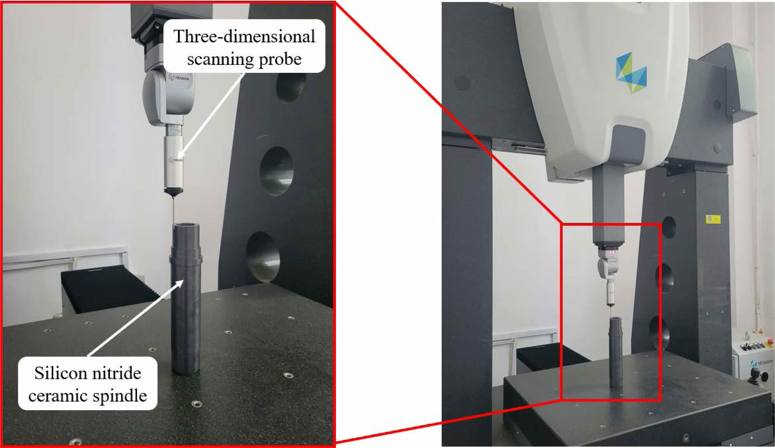
The roundness and cylindricity of the cylindrical surface of the ceramic spindle are detected by the MICRO PLUS three-coordinate measuring instrument, and the detection accuracy is less than 1 μm. The performance parameters of the MICRO PLUS three-coordinate measuring instrument are shown in Table 5, as shown in Fig. 14, which shows the method of detecting the shape and position accuracy of the cylindrical surface of the ceramic spindle by the MICRO PLUS three-coordinate measuring instrument, and calculating the distance and position tolerance between points, lines and surfaces with QUINDOS measuring software. The probe system is a three-dimensional scanning probe of LSP-X5, and the detection rate is 40 points per minute.
The measuring instrument adopts a closed frame design, a fixed gantry design machine, a movable workbench made of granite, and an integral dovetail guide rail design for the base. Pre-loaded air bearing is added between the workbench and the guide rail, equipped with ceramic Z-axis precision guidance system. This structure can effectively ensure the overall rigidity, stability and accuracy of the machine. The measuring system is insensitive to the change of ambient temperature. The motion of each axis is relatively independent, which ensures the motion accuracy of the coordinate axis. Even in the case of using an ultra-long rod, the deflection and bending of any probe can be automatically compensated.
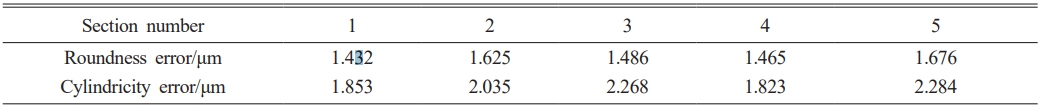
Through orthogonal and single factor experiments, it can be concluded that the surface quality of ceramic spindle is better when the linear speed of grinding wheel is 110 m/s, the transverse feed speed is 5 μm/min, the axial feed speed is 100 mm/min, and the linear speed of workpiece is 0.5 m/s. Therefore, the above grinding parameters are used to grind the ceramic spindle, and the roundness and cylindricity of different sections of the ceramic spindle are detected after machining. Based on the test results in Table 6 and the analysis of the measured data of roundness and cylindricity errors, it is found that the roundness error can be controlled within 1.7 μm and the cylindricity error can be controlled within 2.3 μm. Within this error range, the design requirements of silicon nitride ceramic spindle can be fully met, and the roundness and cylindricity accuracy are high, which can meet the requirements of high-speed stability and dynamic balance performance of all-ceramic electric spindle. This result also shows the feasibility of this processing technology.
|
Fig. 5 Influence of linear speed of grinding wheel on surface roughness. |
|
Fig. 6 The surface morphology was observed by VHX-1000 ultra-depth three-dimensional microscope. |

|
Fig. 7 Depth-of-field map at different lateral feed speeds. |
|
Fig. 8 Geometric contact arc length model. |
|
Fig. 9 Effect of transverse feed speed on surface roughness. |
|
Fig. 10 Effect of axial feed speed on surface roughness. |
|
Fig. 11 Influence of linear velocity of workpiece on surface roughness. |
|
Fig. 12 The surface morphology was observed by Hitachi S-4800 scanning electron microscope. |
|
Fig. 13 Scanning electron microscope images of different workpiece linear velocities. |
|
Fig. 14 Measuring the external circular position accuracy of ceramic spindle with MICRO PLUS three-coordinate measuring instrument |
|
Table 5 Performance parameters of MICRO PLUS three-coordinate measuring instrument. |

|
Table 6 Test results of roundness and cylindricity of different sections of ceramic spindle. |
Selection of optimal machining parameters
In this experiment, a high-precision ultra-high-speed universal cylindrical grinder is used for grinding experiments, and the main optimization parameters are surface roughness value Ra, roundness and cylindricity. The goal of this experiment is to obtain as high surface quality and form and position accuracy as possible in a short processing time, so the best grinding parameters are selected as follows: grinding wheel linear speed 105-115 m/s, transverse feed speed 5-7 μm/min, axial feed speed 100-120 mm/min and workpiece linear speed 0.4-0.6 m/s. Under the processing parameters, the surface quality is good and the processing efficiency is high. It can reduce the processing time and save the cost when used in production.
Build a prediction model of surface roughness
The research shows that there is a complex exponential relationship between various factors affecting surface roughness and surface roughness. Considering the grinding conditions in this paper, a simplified roughness expression is proposed:

Formula: C is the comprehensive influence coefficient related to grinding wheel, grinding temperature, grinding conditions and other factors; k1, k2, k3 and k4 are the undetermined indexes of each grinding parameter.
Because the formula is a nonlinear expression, in order to simplify the calculation, the logarithm of both ends of the above expression is converted into a linear expression, that is lnRa = lnC + k1lnVs + k2lnVr + k3lnVf + k4lnVw, remember to y = k0 + k1x1+ k2x2 + k3x3, that is k0 = lnC,x1 = lnVs,x2 = lnVr,x3 = lnVf,x4 = lnVw. In order to calculate k0,k1,k2,k3,k4. The following linear regression matrix equations can be established by using the experimental data in orthogonal and single factor experiments:

Calculate by using the principle of least square method k0,k1,k2,k3, Then the least squares estimator of K is K=(XTX)-1XTY, Using numerical analysis software for calculation, figure out: k0=0.1466, k1=0.0149, k2=0.0654, k3=0.0306, k4=0.0010.
After calculation, the simplified roughness prediction model can be obtained as follows:

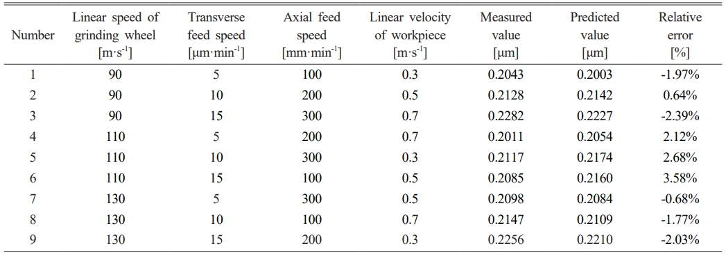
In order to verify whether the roughness expression is correct, the grinding parameters of each group of experiments are brought into equation (8) to obtain the corresponding predicted values. The comparison between the measured values and the predicted values is shown in Table 7.
By comparison, the minimum relative error between the predicted value and the measured value is 0.64%, and the maximum relative error is 3.58%. Therefore, the surface roughness prediction model has a good prediction effect on the grinding of silicon nitride ceramic spindle, and the purpose of predicting the grinding surface roughness is achieved. In actual production and processing, as long as the grinding parameters are reasonable, the grinding surface roughness can be controlled within a certain range, which provides some theoretical guidance for actual production and processing.
Through 1orthogonal and single factor experimental research on silicon nitride ceramic spindle, the influence of different grinding parameters on the surface quality and shape and position accuracy of ceramic spindle is explored, and the conclusions are as follows:
(1) In the process of grinding the excircle surface of silicon nitride ceramic spindle, it generally decreases first and then increases with the increase of grinding wheel linear speed and workpiece linear speed, and increases with the increase of transverse feed speed and axial feed speed. The order of influence of grinding parameters on workpiece surface roughness value Ra is transverse feed speed > grinding wheel linear speed > axial feed speed > workpiece linear speed.
(2) Under the current experimental conditions, the recommended optimal parameters for grinding the excircle surface of silicon nitride ceramic spindle are: grinding wheel linear speed 105-115 m/s, transverse feed speed 5-7 μm/min, axial feed speed 100-120 mm/min, workpiece linear speed 0.4-0.6 m/s, and surface roughness Ra can be controlled within 0.21 μm.
(3) Grinding the excircle surface of silicon nitride ceramic spindle with grinding wheel linear speed of 110 m/s, transverse feed speed of 5 μm/min, axial feed speed of 100 mm/min and workpiece linear speed of 0.5 m/s, the roundness error of the excircle surface of the machined ceramic spindle can be controlled within 1.7 μm, cylindricity error can be controlled within 2.3 μm, and the accuracy of roundness and cylindricity is high, which can fully meet the design requirements of silicon nitride ceramic spindle within such error range.
(4) Compared with the actual measured surface roughness Ra, the minimum relative error of the prediction model is 0.64%, the maximum relative error is 3.58%, and the maximum relative error of the predicted value is less than 5%, which shows that the prediction model has a good prediction effect. Reasonable selection of grinding parameters can predict and control the surface roughness of the excircle of silicon nitride ceramic spindle, which is of great significance to production and processing.
The authors acknowledge the collective support granted by the National Natural Science Foundation of China (Grant No 51975388), Liaoning applied basic research Program (Grant No 2022JH2/101300216).
- 1. B. Chen, Z.H. Wei, B. L, Z.C. Wang, T.F. Wang, Bull. Chin. Ceram. Soc. 41[4] (2022) 1404-1415.
- 2. Y. Lu, J.-Q. Gao, J.-F. Yang, J. Ceram. Process. Res. 9[6] (2008) 657-660.
-

- 3. L.L. Yang, Z.P. Xie, S. Li, M. Song, J. Ceram. 35[05] (2014) 457-464.
- 4. S.H. Ahna, K.W. Nam, J. Ceram. Process. Res. 22[1] (2021) 54-60.
-
- 5. K.L. Wen, D.C. Luan, C.M. Zuo, X.Y. Zhou, L. Liu, S.H. Mi, Z.Y. Wang, Chin. Ceram. 57[08] (2021) 26-32.
- 6. X.W. Qin, Z.P. Xie, Y.D. Yao, H.C. Lei, B.B. Fan, J. Ceram. 43[06] (2022) 971-986.
- 7. L.T. Wei, Y.F. Wu, J. Ceram. Process. Res. 20[3] (2019) 216-221.
-
- 8. Z.B. Fan, Z.M. Chen, X. Zhou, X.T. He, S.J. Jiang, J.W. Dong, Chin. Opt. 14[04] (2021) 998-1018.
- 9. J.L. Li, F. Chen, J.Y. Niu, Y. Yang, Z.H. Wang, J. Ceram. Process. Res. 12[3] (2011) 236-239.
-
- 10. S.H. Li, Y.H. Wu, J. Dalian Univ. Technol. 53[02] (2013) 214-220.
- 11. F. Lu, S.C. Chen, K. Zhang, Y.H. Wu, Adv. Mater. Res. 383-390 (2011) 3361-3365.
-
- 12. F. Lu, S.C. Chen, S.H. Li, K. Zhang, Y.H. Wu, Key Eng. Mater. 487(2011) 99-103.
-
- 13. Y. Liu, B.Z. Li, C.J. Wu, Y.H. Zheng, Int. J. Adv. Manuf. Tech. 86 (2016) 799-808.
-
- 14. S. Agarwal, Ceram. Int. 42[5] (2016) 6244-6262.
-
- 15. S.S. Chen, C.F. Cheung, C.Y. Zhao, F.H. Zhang, Int. J. Adv. Manuf. Tech. 91 (2017) 719-730.
-
- 16. J. Sun, Y.H. Wu, P. Zhou, S.H. Li, L.X. Zhang, K. Zhang, Adv. Mech. Eng. 9[6] (2017).
- 17. X.H. Zhang, Z.C. Zhang, Z.H. Deng, S. Li, Q.P. Wu, Z.X. Kang, Opt. Laser Technol. 109 (2018) 418-428.
-
- 18. X.H. Zhang, D.D. Wen, Z.H. Deng, S. Li, Q.P. Wu, J. Jiang, Int. J. Adv. Manuf. Tech. 96 (2018) 3081-3091.
-
- 19. C.J. Wu, W.C. Guo, Z.P. Wu, K.M. Lu, B.Z. Lu, S.Y. Ling, J. Adv. V. Mech. Des. Syst. 13[3] (2019).
- 20. P. Li, S.Y. Chen, T. Jin, J. Yi, W. Liu, Q.P. Wu, W.Q. Peng, H.F. Dai, Ceram. Int. 47[4] (2021) 4659-4673.
-
- 21. H.P. Yan, F. Deng, H.L. Niu, J.D. Zhu, B.B. Hu, J. Braz. Soc. Mech. Sci. Eng. 43[7] (2021) 1-12.
-
- 22. A. Choudhary, S. Paul, Ceram. Int. 47[21] (2021) 30546-30562
-
- 23. Q.B. Yang, Y.H. You, B.J. Cheng, L. Chen, J. Cheng, D.Y. Lou, Y.T. Wang, Dun Liu, J. Ceram. Process. Res. 24[2] (2023) 230-236.
-
- 24. W. Liu, Z.H. Deng, L.L. Wan, X.Y. Zhao, Z. Pi, J. Mech. Eng. 51[21] (2015) 191-198.
- 25. L.L. Wan, Z.J. Liu, Z.H. Deng, W. Liu, Ordnance Mater. Sci. Eng. 40[2] (2017) 1-7.
- 26. H. Huang, L. Yin, L.B. Zhou, J. Mater. Process. Technol. 141[3] (2003) 329-336.
-
- 27. T.G. Bifano, T.A. Dow, R.O. Scattergood, J. Eng. Ind. 113[2] (1991) 184-189.
-
- 28. Z.P. Li, F.H. Zhang, X.C. Luo, W.L. Chang, Y.K. Cai, W.B. Zhong, F. Ding, J. Eur. Ceram. Soc. 39[4] (2019) 705-717.
-
- 29. F.M. Dai, H.H. Su, K. Zhang, Y.C. Fu, J.H. Xu, Diamond Abrasives Eng. 34[1] (2014) 23-27.
- 30. W.B. ROWE, in “Principles of modern grinding technology” (Oxford University Press, 2013) p.25.
- 31. Y.H. Wu, Y. Sha, S.H. Li, J. Sun, H. Wang, Surf. Technol. 48[12] (2019) 360-368.
- 32. Y.H. Wu, Y. Sha, S.H. Li, J. Sun, H. Wang, J. Ceram. 40[06] (2019) 718-724.
- 33. F. Lu, S.C. Chen, Y. Bao, K. Zhang, Y.H. Wu, Adv. Mater. Res. 328-330 (2011) 569-573.
-
- 34. F. Lu, S.C. Chen, S.H. Li, K. Zhang, Y.H. Wu, Appl. Mech. Mater. 130-134 (2011) 1161-1165.
-
 This Article
-
2023; 24(6): 1025-1036
Published on Dec 31, 2023
- 10.36410/jcpr.2023.24.6.1025
- Received on Nov 14, 2023
- Revised on Nov 20, 2023
- Accepted on Nov 23, 2023
Services
- Abstract
introduction
experiment
results and discussion
optimization of grinding process for ceramic spindle excircle
conclusion
- Acknowledgements
- References
- Full Text PDF
Shared
Correspondence to
- Yonghua Wang
-
School of Mechanical Engineering, Shenyang Jianzhu University, Shenyang 110168, China
Tel : +86-186 2405 7650 Fax: 024-24692192 - E-mail: yonghua0514@sjzu.edu.cn
Clean-Energy Research Institute(CRI), Hanyang University, 222, Wangsimni-ro, Seongdong-gu, Seoul, 04763, Korea
E-mail: jcpr@hanyang.ac.kr