


- Microwave dielectric properties of Li3Mg2SbO5F2 oxyfluorides ceramics produced by reaction-sintering method
Pengshen Wua, Cuijin Peia, Miao Chena, Xu Gaoa, Weihong Liub, Guoguang Yaoa,* and Jin Liuc
aSchool of Science, Xi’an University of Posts and Telecommunications, Xi’an 710121, China
bSchool of Electronic Energineering, Xi’an University of Posts and Telecommunications, Xi’an 710121, China
cSchool of Fine Arts, Shaanxi Normal University, Xi’an, 710062, ChinaThis article is an open access article distributed under the terms of the Creative Commons Attribution Non-Commercial License (http://creativecommons.org/licenses/by-nc/4.0) which permits unrestricted non-commercial use, distribution, and reproduction in any medium, provided the original work is properly cited.
By a reaction-sintering approach Li3Mg2SbO5F2 oxyfluorides ceramics were prepared. The sinterability, microstructure, phase transition along with microwave dielectric performances of present ceramics were researched. A gradual phase transition from cubic to orthorhombic in Li3Mg2SbO5F2 ceramics sintered above 825 °C was identified by XRD refinement analysis. The microwave dielectric performances of present ceramics were closely correlated with its phase transition process and microstructure. Typically, optimal microwave dielectric performances (εr ~ 8.1, τf ~ –54.0 ppm/°C, Q × f ~ 68,500 GHz (under 9.2 GHz)) were achieved for 825 °C-sintered Li3Mg2SbO5F2 ceramics. Moreover, a cylindrical dielectric resonator antenna fabricated from Li3Mg2SbO5F2 ceramics exhibited a maximum return loss (S11) of –30.3 dB, a maximum gain of 5.3 dB and VSWR of 1.1 at the center frequency of 11.6 GHz, and impedance bandwidth of 300 MHz (at –10 dB), respectively.
Keywords: Ceramics, Li3Mg2SbO5F2 oxyfluorides, microwave dielectric properties, antenna
The urge of 5G/6G technology is proliferation for its low latency. To accomplish the low latency, dielectric ceramics with a low dielectric constant (ɛr≤10) is internal demand to reduce latency of the components [1]. Simultaneously, a high quality factor (Q×f), an approximating zero resonant frequency temperature coefficient (τf), and an inherent low sintering temperature (below 950 oC) are also the essential requires for microwave dielectric ceramics, which is beneficial for lower signal attenuation, better environment stability and further cost reduction [2-4]. Thus, immense attentions have been pay to develop new dielectric ceramics with above performances concurrently.
Recently, researchers started to enlarge new microwave dielectric ceramics from oxides to oxyfluorides-containing LiF. It was reported that the partial chemical fluorination (O2- is replaced with F-) not only decrease the sintering temperature, but also reduce the ɛr of oxides ceramics [5]. For instance, a series of oxyfluorides ceramics such as Li2+xMg1−xTi3O8−xFx (τƒ = -6.0 ppm/oC, Qf = 55,000 GHz, εr=24.8, fired at 1100 oC), Li3TiO3F (Qf = 96, 200 GHz, εr=17.3, τƒ = -32.7 ppm/oC, fired at 900 oC), Li4NbO4F (Qf = 61,100 GHz, εr=15.2, τƒ = -51.0 ppm/oC, fired at 825 oC), Li4MgNbO5F (Q×f = 93,000 GHz, εr=15.5, and τƒ = -40.0 ppm/◦C, fired at 900 oC), Li8MgxTi3O9+xF2 (Q×f = 119,700 GHz, εr=16.8, τƒ = -41.6 ppm/oC, fired at 875 oC) were reported, which exhibited promising microwave dielectric properties and inherit low sintering temperature [6-8]. The chemical fluorination turns out to be an effective approach for remarkable lowering the sintering temperature of oxides ceramics [9, 10]. In these oxyfluorides ceramics-containing LiF, two distinct low temperature sintering mechanisms have been invoked: one is connected with liquid phase sintering caused by the low melting point of LiF (845 oC), the other is due to the reduced chemical potential caused by F- substitution for O2- ions; or both [11-13]. However, consensus about the sintering mechanism of oxyfluorides ceramics using LiF as fluorine source. To explore the exact sintering mechanism of the oxyfluorides ceramics, a new oxyfluoride ceramics, namely Li3Mg2SbO5F2, was designed using high melting point MgF2 (1250 oC) instead of LiF as reactive source of fluorine [14]. In present paper, we demonstrate the possibility to fabricate Li3Mg2SbO5F2 by reaction sintering route. The effects of using MgF2 as fluorine source on the sinterability, phase constitutions, microstructure and dielectric properties in microwave frequency for Li3Mg2SbO5F2 ceramics were systematically investigated. Besides, a cylindrical dielectric resonator antenna (CDRA) was manufactured and measured from Li3Mg2SbO5F2 for X-band applications.
The raw materials are high-purity powders: Sb2O3 (99.0%, Guo Yao Co., Ltd.), MgF2 (99.99%, Aladdin), Li2CO3 (98.0%, Guo Yao Co., Ltd.), and MgO (99.9%, Guo Yao Co., Ltd.). According to stoichiometric Li3Mg2SbO5F2, the starting materials were weighed followed by milling for 8 h in ethanol. The milling powders were stoved, then granulated and molded, finally sintered for 5 h (800 ℃-875 ℃). The specific reaction sintering process has been described in our former work [15].
By Archimedes’ drainage method, the apparent densities in Li3Mg2SbO5F2 sintered bodies were evaluated. The crystal structure as well as phase transition were measured using powder X-ray diffraction (PXRD, PANalytical) at ambient temperature. PXRD data were collected in a 2θ region of 5-100owith a step size of 0.015o. The microstructural morphology for fired ceramics was examined via a scanning electron microscope. The antenna performances along with microwave dielectric performances of present samples were estimated via a Rohde & schwarz network analysis (ZVB20, Germany). In the temperature region of 25-85 °C, the τf had been determined via the following formula:
The cylindrical dielectric resonator antenna (CDRA) was designed using the High-Frequency Structure Simulator software.
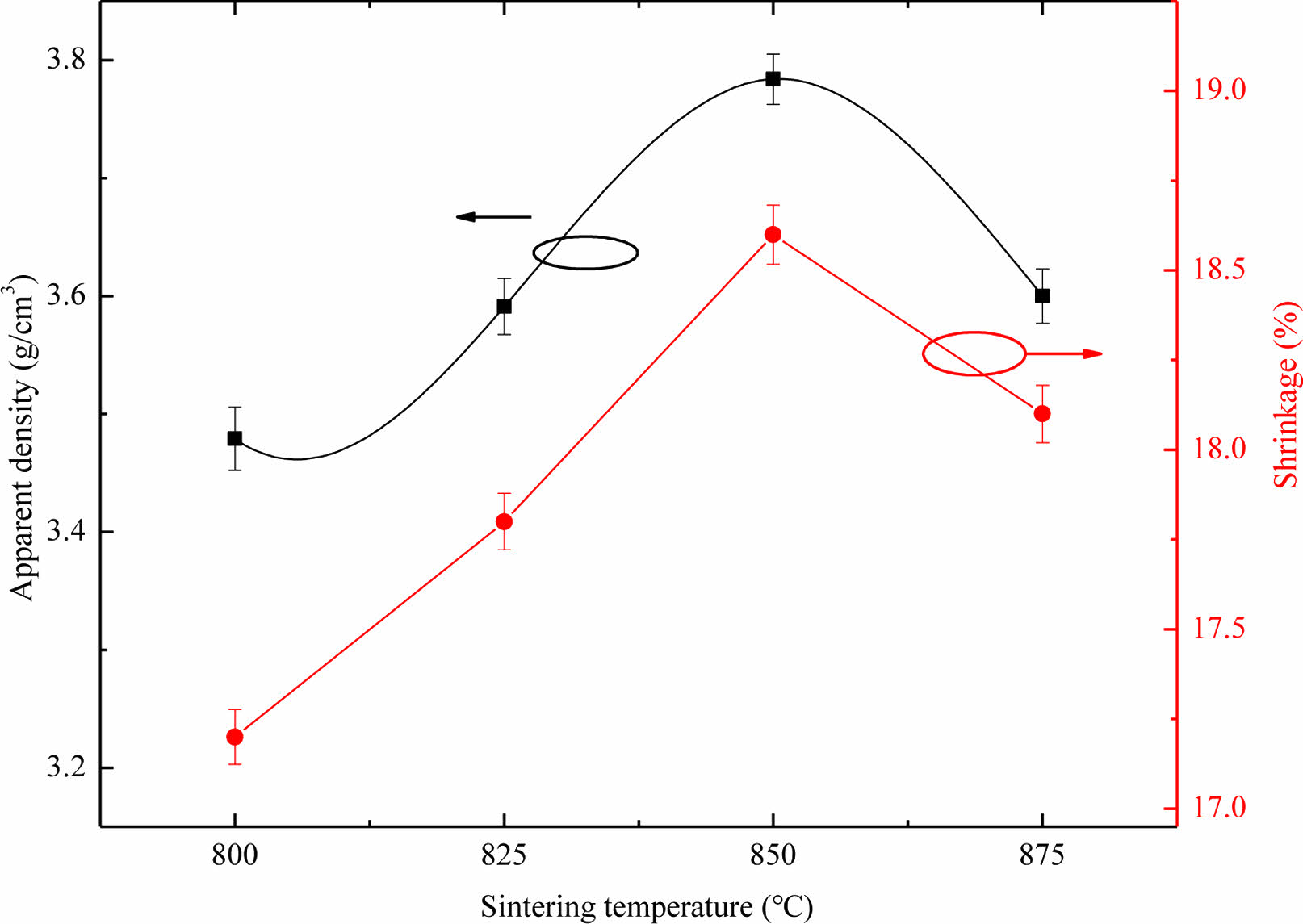
The dense degree of Li3Mg2SbO5F2 ceramics were evaluated via radial shrinkage and apparent density (ρap). Fig. 1 illustrates the ρap and radial shrinkage of Li3Mg2SbO5F2 ceramics sintered at 800-875 oC. As seen in Fig. 1, both the ρap and radial shrinkage exhibited the similar variational tendency with the increase of firing temperature. As the firing temperature increased, both the ρap and radial shrinkage initially increased, reached their respective maximum values at 850 oC, and then declined. As the heating temperature increase, the enhancement of ρap for Li3Mg2SbO5F2 ceramics was due to the reduction of internal pores, while its abatement was due to over-sintering, which was consistent with the microstructure observation intuitively as discussed below.
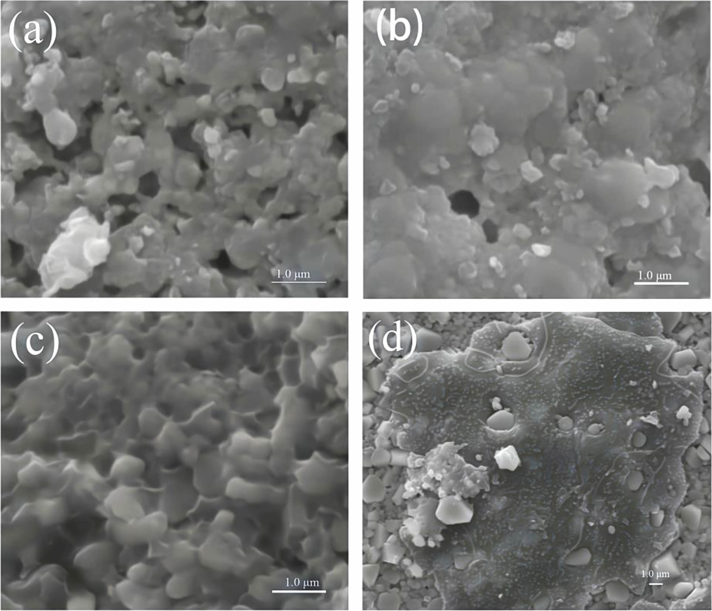
The typical SEM photographs at different sintering temperature of Li3Mg2SbO5F2 ceramics are exhibited in Fig. 2. Some intergranular pores were observed for 775 ℃-sintered sample, corresponding to its relatively lower ρap, as seen in Fig. 2(a) and Fig. 1. The number of intergranular pores vanished gradually in line with enhancement of firing temperature, and a relative uniformly dense microstructure were achieved for 850 ℃-sintered sample. When the firing temperature reached 875 ℃, a residual liquid phase wrapped grains was appeared due to over-sintered, which would result in an adverse effect on present ceramics’ density and dielectric performances [16].
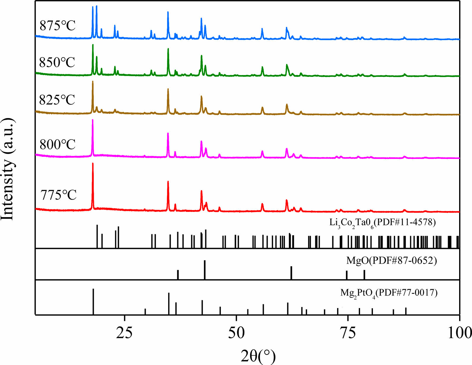
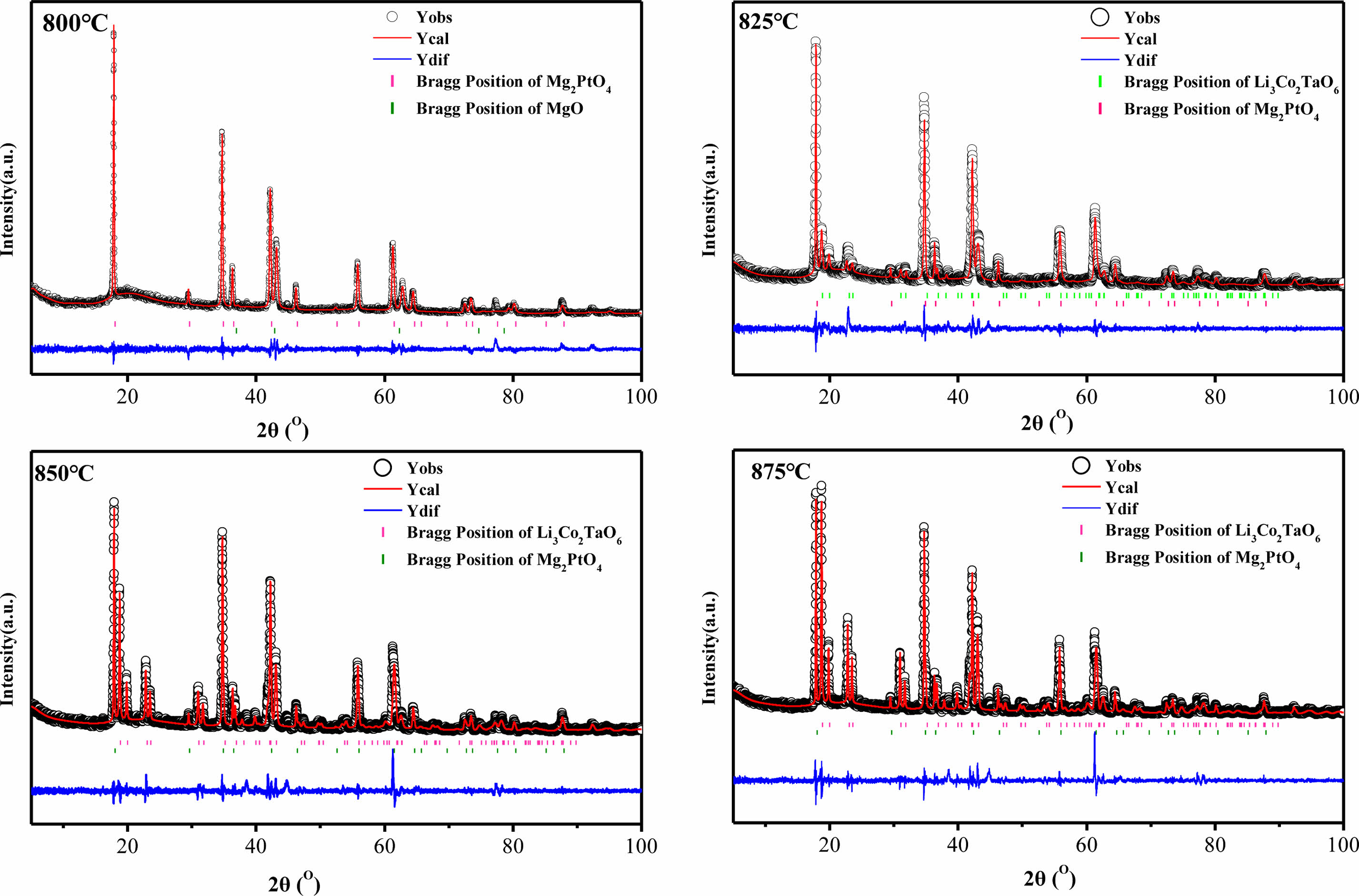
Fig. 3 gives the XRD profiles of Li3Mg2SbO5F2 ceramics sintered under 800-875 oC. The main diffraction peaks of 775 oC and 800 oC-sintered samples individually matched well with the standard PDF cards of Mg2PtO4 (#77-0017) with a cubic rock salt structure and Li3Mg2SbO6 (#87-0652) with an orthorhombic rock salt structure, and some tiny peaks matched well with the standard PDF card of MgO (#78-0430). When the sintering temperature exceeded 825 oC, the trace phase of MgO vanished, and the content of Li3Mg2SbO6 phase increased with augment of sintering temperature, indicating that partial cubic phase transformed to an orthorhombic phase. This structural transformation was also found in previous studies [8], which may influence present ceramics’ dielectric properties [17, 18].
To further identify the detailed structure information along with quantity of each phase, the Rietveld refinements of XRD data of Li3Mg2SbO6F2 samples were conducted. Fig. 4 illustrates the fitted and measured XRD profiles using cubic Mg2PtO4 and orthorhombic Li3Mg2SbO6 as initial models, the detailed refinement results are summarized in Table 1. A good match between the fitted and measured diffraction patterns along with low reliability factors suggested the structure model and refined results were creditable. From Table 1, the quantity of orthorhombic structural phase increased from 40.1 to 61.8%, with an enhancement of sintering temperature from 825 to 875 oC.
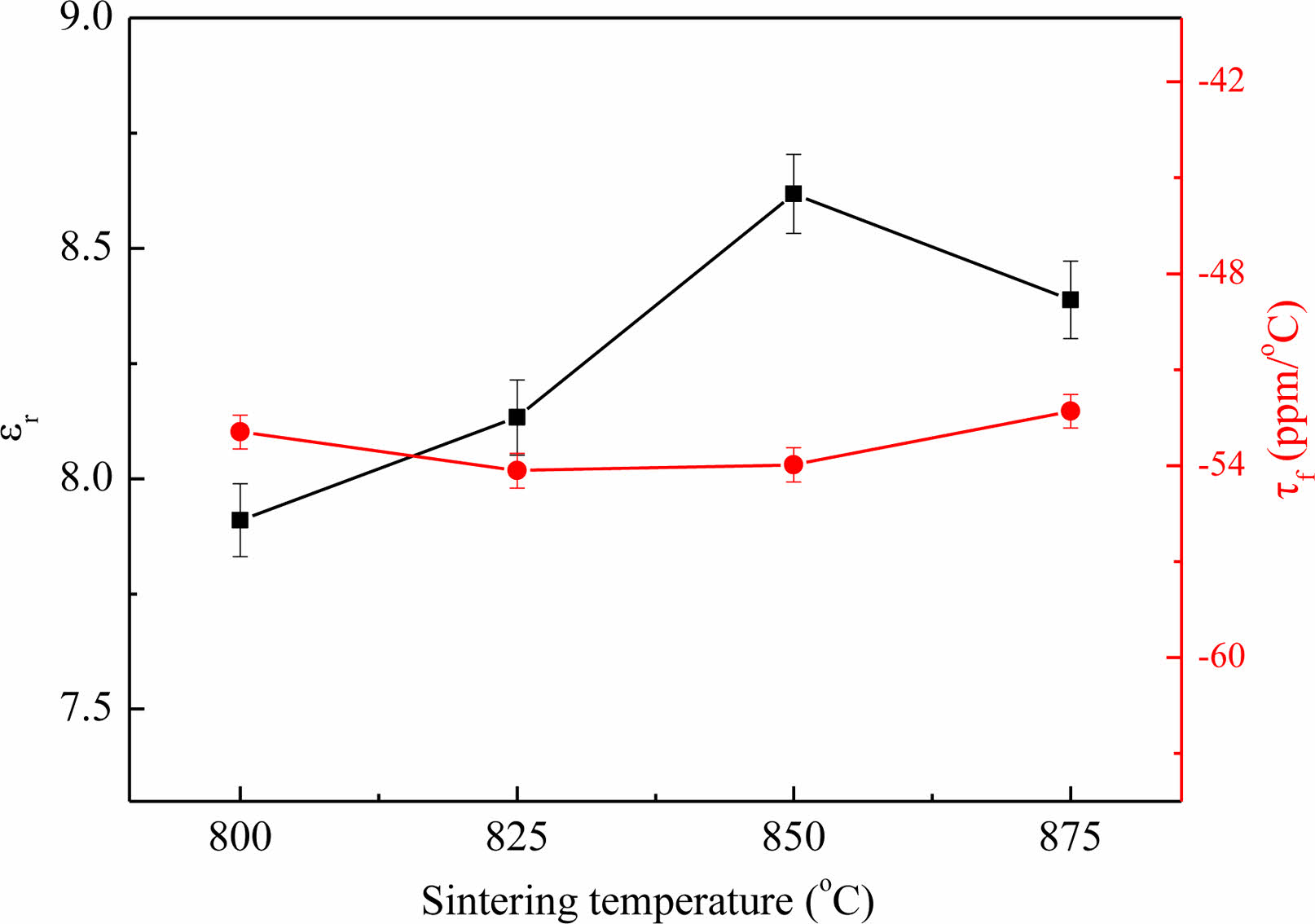
The plots of ɛr and τf of Li3Mg2SbO5F2 ceramics with various heating condition are exhibited in Fig. 5. With augment of heating temperature, the ɛr rose first and achieved a saturation value around 8.6 at 850 ℃ and subsequently declined. Evidently, the ɛr and ρap exhibited a similar variational tendency with the sintering temperature, which suggested the ɛr is deeply linked with the ρap. Moreover, in the temperature range of 800-875 oC, the τf retained steady at -53 ppm/oC regardless of the sintering temperature, although the phases transferred from cubic to orthorhombic.
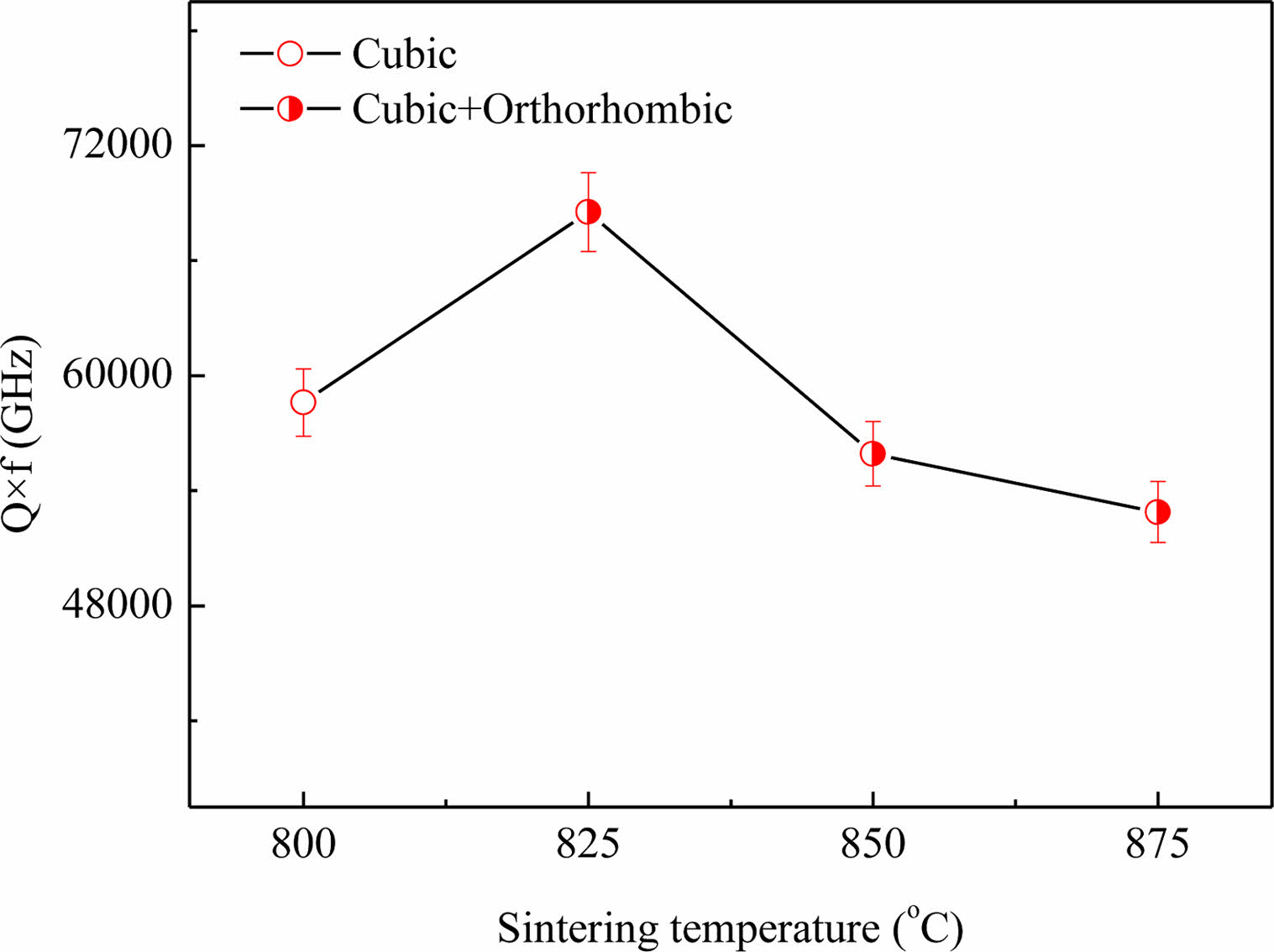
Fig. 6 shows the dependence of the Q×f in Li3Mg2SbO5F2 ceramics on sintering temperature. The tendency variation of Q×f was initially rose from the onset of 58,600 GHz at 800 oC to a maximum value of 68500 GHz at 825 oC, and then decreased gradually to 52800 GHz at 875 oC. The tendency of variation of Q×f was somewhat different from ρap versus sintering temperature, indicating others factor except ρap that could affect the Li3Mg2SbO5F2 ceramics’ Q×f. Overall, the Q×f is determined by inherent factors (like ordering, symmetry, and phonon vibration) and extrinsic factors (like pores, inclusions and distortion) [19-21]. For given ceramics with high symmetry showed a high Qxf due to its high structural stability [22]. In our cases, the initial improvement of Q×f was due to the reduce of pores (seen Fig. 2). Subsequently, the degradation of Q×f was attributed to the increased content of orthorhombic phase with low symmetry (seen Table 1) , and the reduce of ρap (seen Fig. 1) owing over-sintering. The similar effect of phase transition on Q×f was also reported by Ohsato et al. [23].
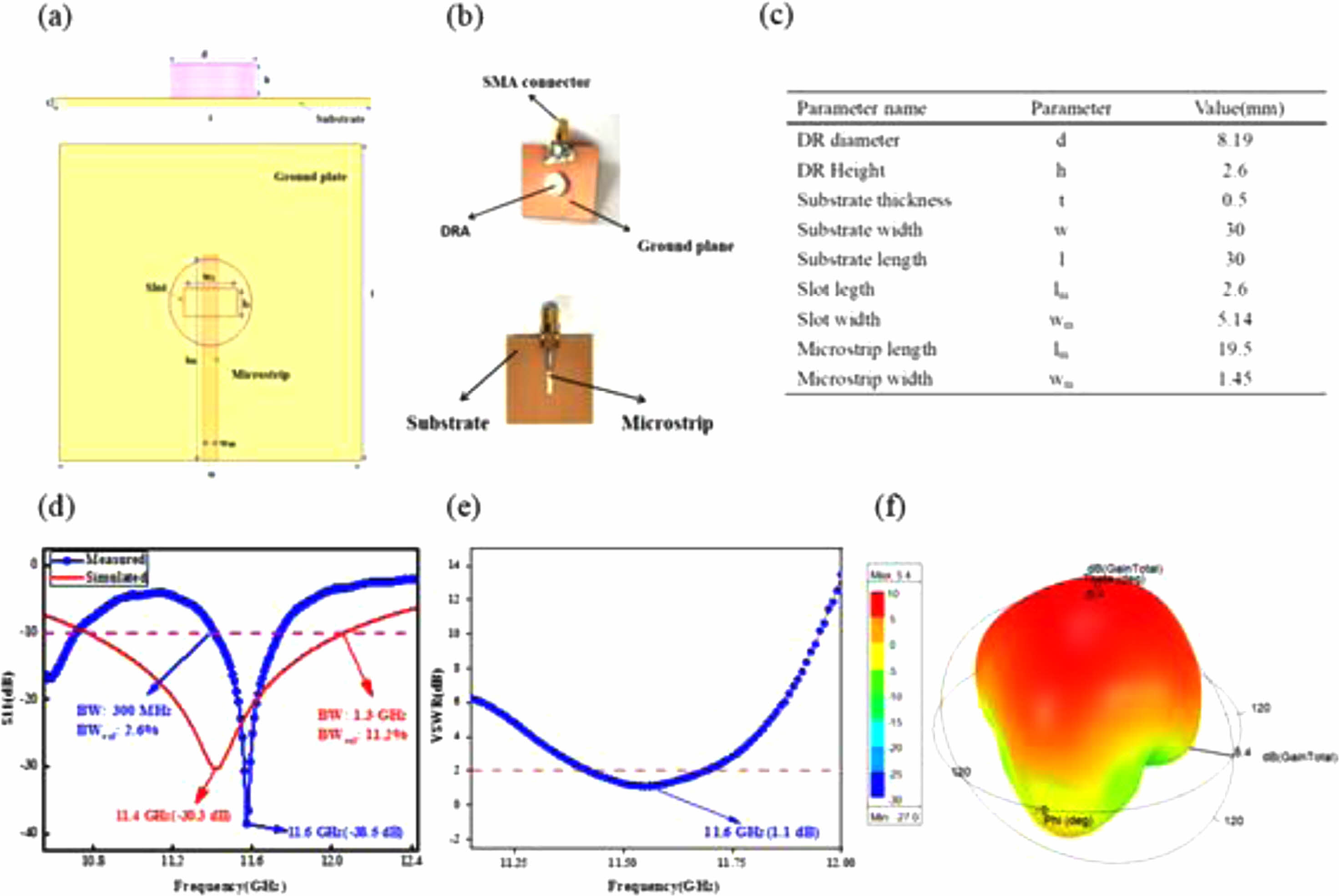
Feasibility evaluation of Li3Mg2SbO5F2 ceramics serving as CDRAs in X-band range is demonstrated. The sketch, prototype and final optimized parameters of Li3Mg2SbO5F2-based CDRA are displayed in Fig. 6(a)-(c). Fig. 6(d) displays the numerical and measured reflection characteristics (S11) curves of the Li3Mg2SbO5F2 CDRA. The numerical S11 of -32.7 dB at central frequency of 11.4 GHz has an impedance bandwidth of 1.3 GHz (10.8-12.1 GHz) compared to the measured S11 of -38.5 dB at 11.6 GHz with an impedance bandwidth of 300 MHz (11.4-11.7 GHz). The above mismatch in central frequency, S11 along with antenna bandwidth of the simulated and fabricated antenna are due to the fabrication process’s preciseness, tiny position alteration of DR, and SMA connector’s welding, etc [24]. As presented in Fig. 6(e), the measured VSWR of CDRA was 1.1 at 11.6 GHz and below 2 within the bandwidth of 300 MHz (11.4-11.7 GHz). Fig. 6(f) presents the numerical three-dimensional gain plot of the simulated antenna, which showed a maximum gain of 5.4 dB along Z direction. Table 2 gives CDRA performances made of different dielectric ceramics for X-band applications. From Table 2, our Li3Mg2SbO5F2 CDRA displays comparable antenna performances with that of other CDRAs. Moreover, it points out that our CDRA displays a very good trade-off between gain, bandwidth and return loss (S11). Fig. 7
|
Fig. 1 Apparent density and radial shrinkage of Li3Mg2SbO5F2 ceramics sintered at 800-875 oC. |
|
Fig. 2 SEM photographs at different sintering temperature of Li3Mg2SbO5F2 ceramics: (a) 800 oC, (b) 825 oC, (c) 850 oC, (d) 875 oC. |
|
Fig. 3 XRD patterns of Li3Mg2SbO5F2 ceramics sintered at 800-875 oC. |
|
Fig. 4 Rietveld refinement profiles of Li3Mg2SbO5F2 sintered at 800-875 oC. |
|
Fig. 5 The plots of ɛr and τf in Li3Mg2SbO5F2 ceramics with sintering temperature. |
|
Fig. 6 Q×f curve of Li3Mg2SbO5F2 ceramics with sintering temperature. |
|
Fig. 7 The schematic (a) and prototype (b) of simulated and fabricated CDRA, (c) optimized parameter values, (d) simulated and tested return loss (S11), (e) tested voltage standing wave ratio (VSWR), and (f) simulated 3D radiation pattern at 11.6 GHz. |
|
Table 1 Refinement results of Li3Mg2SbO5F2 ceramics sintered at 800-875 oC |
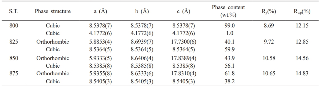
S.T.: sintering temperature |
|
Table 2 CDRA performances comparison of different dielectric ceramics for X-band applications |
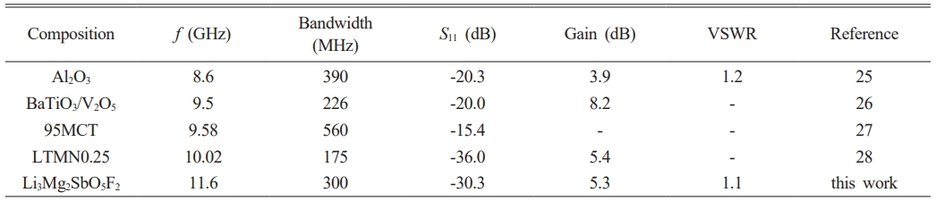
*-: not mentioned |
Microwave dielectric performances and evolution of phase structure of Li3Mg2SbO5F2 ceramics prepared by reactive sintering method have been reported. A phase transition from cubic to orthorhombic occurred at above 825 oC as identified by XRD refinement analysis. The phase transition process and microstructure take a vital effect on the microwave dielectric performances of present ceramics. Typically, 825 °C-sintered Li3Mg2SbO5F2 specimens exhibited microwave dielectric performances (εr ~ 8.1, τf ~ −54.0 ppm/°C, Q × f ~68,500 GHz (under 9.2 GHz)).Moreover, a cylindrical dielectric resonator antenna made from Li3Mg2SbO5F2 ceramics was designed for X-band applications, which exhibited return loss (S11) of -38.5 dB, gain of 5.4 dB, VSWR of 1.1, and -10 dB bandwidth of 300 MHz at the center frequency of 11.6 GHz, respectively.
The authors acknowledge supports from National Natural Science Foundation of China (Grant Nos. 52002317, 52272122), Xi’an Sciences Plan Project (No. 2021XJZZ0075), and Undergraduate Innovation and Entrepreneurship Training Program in China (No. 202211664020).
- 1. T.H. Hsu, C.L. Huang, Mat. Sci. Semicon. Proc. 158 (2023) 107355.
-

- 2. J. Liu, B. Liu, C.C. Hu, Q.W. Zhou, K.X. Song, J. Eur. Ceram. Soc. 43[14] (2023) 6130-6136.
-
- 3. Y.S. Park, E.S. Kim, J. Ceram. Process. Res. 23[6] (2022) 920-926.
-
- 4. S. Kim, C.B. Hong, S.H. Kwon, S.O. Yoon, J. Ceram. Process. Res. 18[6] (2017) 421-424.
-
- 5. S.H. Han, Y.N. Li, F.Y. Hao, H. Zhou, S.L. Qi, G.F. Tian, D.Z. Wu, Eur. Polym. J. 143 (2021) 110206.
-
- 6. X. Chu, J. Jiang, J.Z. Wang, Y.C. Wu, L. Gan, T.J. Zhang, Ceram. Int. 47[3] (2021) 4344-4451.
-
- 7. P. Zhang, M.M. Yang, M. Xiao, Z.T. Zheng, Mater. Chem. Phys. 236 (2019) 121805.
-
- 8. Z.X. Wang, Y.F. Guo, J.M. Li, C.H. Li, Ceram. Int. 49 (2023) 33425-33431.
-
- 9. K. Xiao, C.C. Li, Y. Tang, Y.F. Tian, C.Z. Yin, J.Q. Chen, J. Li, L. Duan, H.C. Xiang, L. Fang, J. Alloys. Compd. 835 (2020) 155320.
-
- 10. L.M. Huang, J.J. Bian, J. Eur. Ceram. Soc. 43[15] (2023) 6893-6899.
-
- 11. X.H. Zhang, Y.M. Ding, J.J. Bian, J. Mater. Sci-Mater. El. 28 (2017) 12755-12760.
-
- 12. A. Kan, R. Hirabayashi, S. Takahashi, H. Ogawa, Ceram. Int. 49[6] (2023) 9883-9892.
-
- 13. W. Jin, J.J.Tan, J.X. Yan, Y. Tao, N.N. Yao, X.M. Ruan, Pei, C.J. J. Ceram. Process. Res. 22[6] (2021) 675-678.
-
- 14. X.L. Fan, J.T. Fan, K.C. Qian, Z.Y. Shen, L.L. Zhang, B.X. Jiang, T. Feng, L. Zhang, J. Eur. Ceram. Soc. 15 (2022) 7203-7208.
-
- 15. G.G. Yao, J. Ceram. Process. Res. 16[1] (2015) 41-44.
-
- 16. S.O. Yoon, S. Kim, Y.H. Kim, S.J. Kim, S.M. Jeong, J. Ceram. Process. Res. 17[10] (2016) 1024-1027.
-
- 17. X. Zhang, Z.X. Fang, H.Y. Yang, P. Zhao, X. Zhang, Y.P. Li, Z. Xiong, H.C. Yang, S.R. Zhang, B. Tang, Acta. Mater. 206 (2021) 116636.
-
- 18. X. Zhang, Z.X. Fang, Z. Xiong, H.Y. Yang, S.R. Zhang, B. Tang, J. Phys. Chem. C. 124 (2020) 22069-22081.
-
- 19. H. Ohsato, J. Varghese, H.L. Jantunen, Electromagnetic Materials and Devices, 2020: 1-26.
-
- 20. E. Schlömann, Phys. Rev. 135 (1964) 412-418.
-
- 21. Y.M. Ding, J.J. Bian, Mater. Res. Bull. 48 (2013) 2776-2781.
-
- 22. H. Ohsato, J. Varghese, H. Jantunen, Electromagnetic Materials and Devices, 3 (2020).
-
- 23. H. Ohsato, J. Varghese, A. Kan, J.S. Kim, I. Kagomiy, H. Ogawa, M.T. Sebastian, H. Jantunen, Ceram. Int. 47[2] (2021) 2735-2742.
-
- 24. R. Madhuri, A. Rajan, S. Ganesanpotti, Mater. Res. Bull. 158 (2023) 112069.
-
- 25. A. Sharma, K. Khare, S.C. Shrivastava, Electronics and Instrumentation Engineering 2 (2013) 2247-2252.
- 26. R. Chandran, C.O. Sreekala, S.K. Menon, Materials Today: Proceedings 33 (2020) 1367-1370.
-
- 27. Y.C. Chen, S.M. Tsao, C.S. Lin, S.C. Wang, Y.H. Chien, J. Alloy. Compd. 471 (2009) 347-351.
-
- 28. H.H. Guo, D. Zhou, C. Du, J. Mater. Chem. C 8 (2020) 4690-4700.
-
 This Article
-
2023; 24(6): 977-982
Published on Dec 31, 2023
- 10.36410/jcpr.2023.24.6.977
- Received on Sep 3, 2023
- Revised on Oct 9, 2023
- Accepted on Oct 28, 2023
Services
- Abstract
introduction
experimental
results and discussion
conclusions
- Acknowledgements
- References
- Full Text PDF
Shared
Correspondence to
- Guoguang Yao
-
School of Science, Xi’an University of Posts and Telecommunications, Xi’an 710121, China
Tel : +86 29 88166089 Fax: +86 29 88166333 - E-mail: yaoguoguang@xupt.edu.cn
Clean-Energy Research Institute(CRI), Hanyang University, 222, Wangsimni-ro, Seongdong-gu, Seoul, 04763, Korea
E-mail: jcpr@hanyang.ac.kr