


- Electrocaloric properties of BaTiO3/La0.7Sr0.3MnO3/BaTiO3 multilayer thin films prepared by chemical solution deposition
Jae-Uk Leea, Jeong-Eun Limb, Ji-Soo Yukb, Sam-Haeng Yib,c, Myung-Gyu Leeb,c, Joo-Seok Parkc,
Young-Gon Kima and Sung-Gap Leea,b,*aMajor in Ceramic Engineering, School of Materials Science and Engineering, Gyeongsang National University, Jinju 52828, Korea
bDepartment of Materials Engineering and Convergence Technology, Research Institute for Green Convergence Technology, Gyeongsang National University, Jinju 52828, Korea
cBusiness Support Division, Korea Institute of Ceramic Engineering and Technology, Jinju 52851, Korea
dDepartment of Electronics, Chosun College of Science and Technology, Gwangju 61453, KoreaThis article is an open access article distributed under the terms of the Creative Commons Attribution Non-Commercial License (http://creativecommons.org/licenses/by-nc/4.0) which permits unrestricted non-commercial use, distribution, and reproduction in any medium, provided the original work is properly cited.
BaTiO3/La0.7Sr0.3MnOs/BaTiO3 multilayer films are fabricated using the chemical solution deposition and spin-coating method. The upper BT film exhibits an average grain size of approximately 42 nm, indicating a uniform and dense microstructure. The single-coated film has an average thickness ranging from 40 to 45 nm. A phase transition temperature of approximately 4 °C is observed in all films. The BT/LSMO/BT multilayer film, coated with LSMO four times, demonstrates a maximum dielectric constant of 2008 at 20 °C. The BT/LSMO/BT multilayer film, coated with LSMO two times, shows a ΔT of 0.59 K at 24 °C. The remnant polarization, coercive field, and ΔT/ΔE of the BT/LSMO/BT multilayer film, coated with LSMO four times, are 19.8 μC/cm2, 42 kV/cm, and 4.56 mKcm/kV, respectively
Keywords: BaTiO3/La0.7Sr0.3MnOs/BaTiO3, Multilayer films, Electrocaloric effect, Polarization.
The electrocaloric (EC) effect was initially observed in Rochelle salt in the 1930s by P. Kobeko et al. [1]. In 2006, A. S. Mischenko et al. reported remarkable EC properties in Pb(Zr0.95Ti0.05)O3 thin films near its Curie temperature of 222°C [2]. This discovery attracted attention towards the utilization of ferroelectric materials as a promising cooling material, capable of overcoming drawbacks associated with traditional vapor-compression refrigeration systems, such as device scaling, noise, vibration, and environmental concerns. Typically, the best EC effect occurs close to the transition temperature, known as the Curie temperature. To achieve excellent EC properties near room temperature, researchers have been investigating various approaches, including the addition of impurities, compositional modifications, and alterations in the manufacturing process for different ferroelectric materials like Pb(Zr,Ti)O3, BaTiO3, and K(Ta,Nb)O3 et al. [3,4].
Perovskite BaTiO3 (BT) undergoes crystal structure transitions as the temperature decreases, reaching the cubic, tetragonal, orthorhombic, and rhombohedral structures at 130 °C, 0 °C, and -90 °C, respectively. BT demonstrates exceptional dielectric, piezoelectric, and ferroelectric properties, and its electronic properties can be controlled through variations in fabrication processes and the introduction of impurities [5, 6]. Perovskite R1-xAxMnO3 (R = trivalent rare-earth ions, A = divalent alkaline-earth ions) exhibits resistance change characteristics attributed to a transition from a ferromagnetic metal to a charge-ordered insulator, which is dependent on the composition of elements and temperature [7]. Specifically, the substitution of Sr2+ for La3+ at the A-site leads to hole doping, compensating for charge inhomogeneity and resulting in the partial transformation of Mn3+ into Mn4+ ions at the B-sites. The coexistence of Mn3+ and Mn4+ ions gives rise to a colossal magnetoresistive effect driven by the double exchange (DE) interaction mediated by neighboring oxygen ions [8]. Exploiting the resistance change characteristics in the presence of a magnetic field, extensive research is being conducted for various applications, including magnetic field sensors, spintronic devices, and temperature sensors [9, 10].
In general, ferroelectric materials exhibit an increase in ion displacement in response to an external electric field near their phase transition temperature due to the coexistence of ferroelectric and paraelectric phases and the instability in the crystal structure caused by thermal fluctuations. The electrocaloric properties also exhibit a maximum value near the phase transition temperature [11, 12]. In this study, BT/LSMO/BT multilayer films, with (La0.7Sr0.3)MnO3 (LSMO) positioned between the BaTiO3 (BT) layers, were fabricated using a chemical solution deposition method. The structural and electrical properties were measured by varying the thickness of the LSMO layer, and the potential for application as EC cooling devices was investigated.
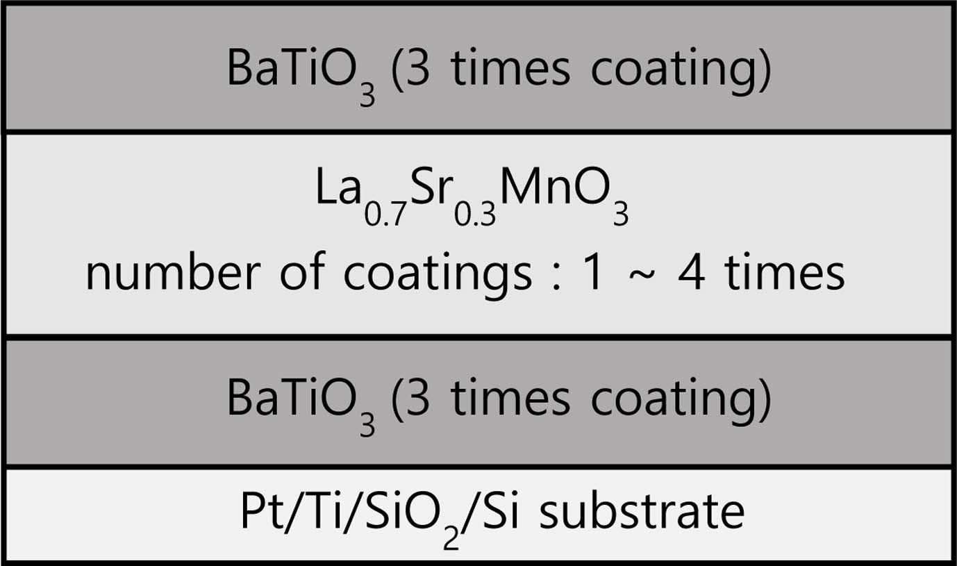
BT and LSMO precursor solutions were prepared using the chemical solution synthesis method. For BT solution, Ba(CH3COO)2 and Ti[OCH(CH₃)₂]₄ were used as starting materials, with acetic acid and 2-methoxyethanol serving as solvents. LSMO solution utilized La(CH3COO)3·xH2O, Sr(CH3COO)2 and Mn(CH3COO)2·4H2O as starting materials, with acetic acid, ethyl alcohol, and distilled water as solvents. The BT coating solution was then spin-coated onto a Pt/Ti/SiO2/Si substrate at 4,000 rpm for 30 seconds. The coated film was dried and subjected to heat treatment at 200 °C for 5 minutes, followed by 400 °C for 10 minutes. This spin-coating, drying, and pyrolysis cycle was repeated three times. Subsequently, the LSMO coating solution was spin-coated and dried on the BT films under the same conditions. The number of coatings for LSMO varied from 1 to 4 times. Finally, the BT coating solution was spin-coated and dried on the LSMO/BT films for three additional cycles under the same conditions. The sintering temperature and time were 800 oC and 1 h, respectively. The crystallographic and structural characteristics of the BT/LSMO/BT multilayer films were analyzed using X-ray diffraction (XRD) and field-emission scanning electron microscopy (FE-SEM). To measure the electrical properties, a Pt top electrode was deposited using the magnetron sputtering method. The P-E hysteresis were measured using a ferroelectric tester (RT-66B, Radiant Tech. Inc. USA), and the applied voltage was up to ±10V, which is the maximum built-in drive voltage of the measuring instrument. Fig. 1 presents a schematic cross-sectional diagram of BT/LSMO/BT multilayer films.
|
Fig. 1 Schematic diagram of BT/LSMO/BT multilayer films. |
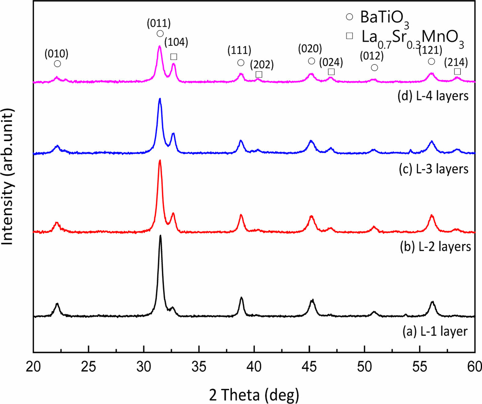
Fig. 2 shows the XRD patterns of BT/LSMO/BT multilayer films. The diffraction peaks corresponding to the BT and LSMO films were clearly observed. The X-ray diffraction characteristics of thin films are generally sensitive to factors such as lattice mismatch with the substrate or underlying layers, thickness, and fabrication processes[reference]. The diffraction intensity of the upper BT layer decreased, and the Full Width at Half Maximum (FWHM) increased as the thickness of LSMO film increased. This is believed to be due to the increase in crystallographic stability with the increasing thickness of the underlying LSMO layer and the strain effect resulting from lattice mismatch with the BT layer [13].
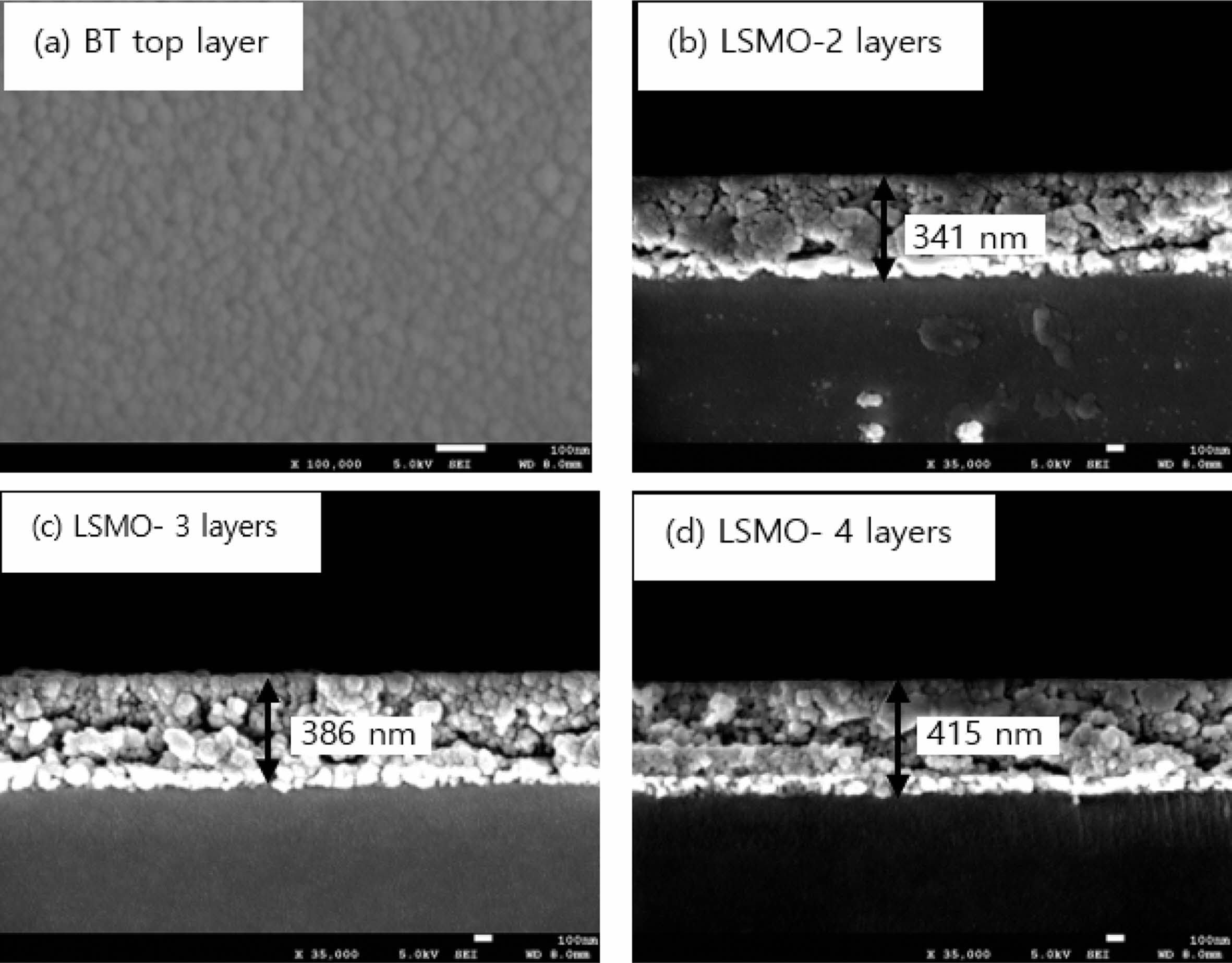
Fig. 3 shows the surface (a) and cross-sectional (b-d) microstructures of the BT/LSMO/BT multilayer film. The upper BT film exhibited a uniform and dense microstructure, with an average grain size of approximately 42 nm. In the cross-sectional view, the BT/LSMO/BT multilayer film displayed a granular crystal structure, with no clear distinction between the BT and LSMO layers. The presence of large voids within the film is believed to be a result of external impact during the handling process of the specimen. The average thickness of a single-coated film was approximately 40-45 nm.
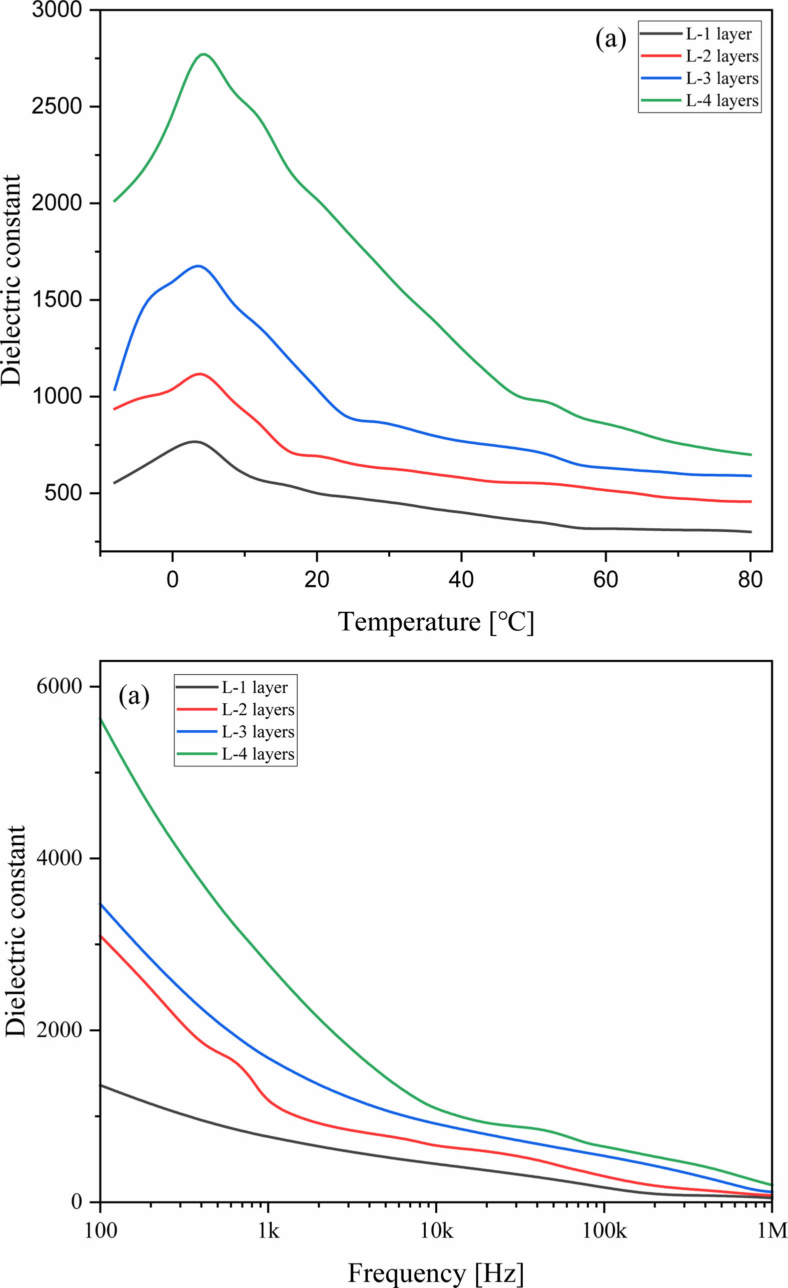
Fig. 4 shows the temperature dependence (a) and frequency dependence (b) of the dielectric constant for the BT/LSMO/BT multilayer films. In bulk BT material, the transition temperature between the tetragonal and orthorhombic structures is typically around 0 °C [14]. However, in the case of the BT/LSMO/BT multilayer films, the phase transition temperature was observed to occur at around 4 °C. This shift in transition temperature is attributed to the stress generated at the interface between the Si substrate and the BT film [15]. As the number of LSMO coating layers increased, the dielectric constant showed an increasing trend. When Sr2+ replaces La3+ in the LSMO film, Mn3+ (0.645 Å) within the oxygen octahedron undergoes a transformation into Mn4+ (0.53 Å), which have a smaller ionic radius, in order to maintain electrical neutrality. Therefore, it is inferred that as the thickness of LSMO increases, the dipole moment between the Mn4+ with smaller ionic radius and oxygen anions increases when an electric field is applied [16]. Also, the increase in the thickness of the LSMO layer can result in a relatively decrease in the lattice mismatch and compositional fluctuation at the interface between BT and LSMO layers, which can lead to a decrease in scattering of the electric field and an increase in the dielectric constant. The dielectric constant of BT/LSMO/BT multilayer film can decrease with an increasing of applied frequency due to the limited mobility of charges and the relaxation of dipoles moment.
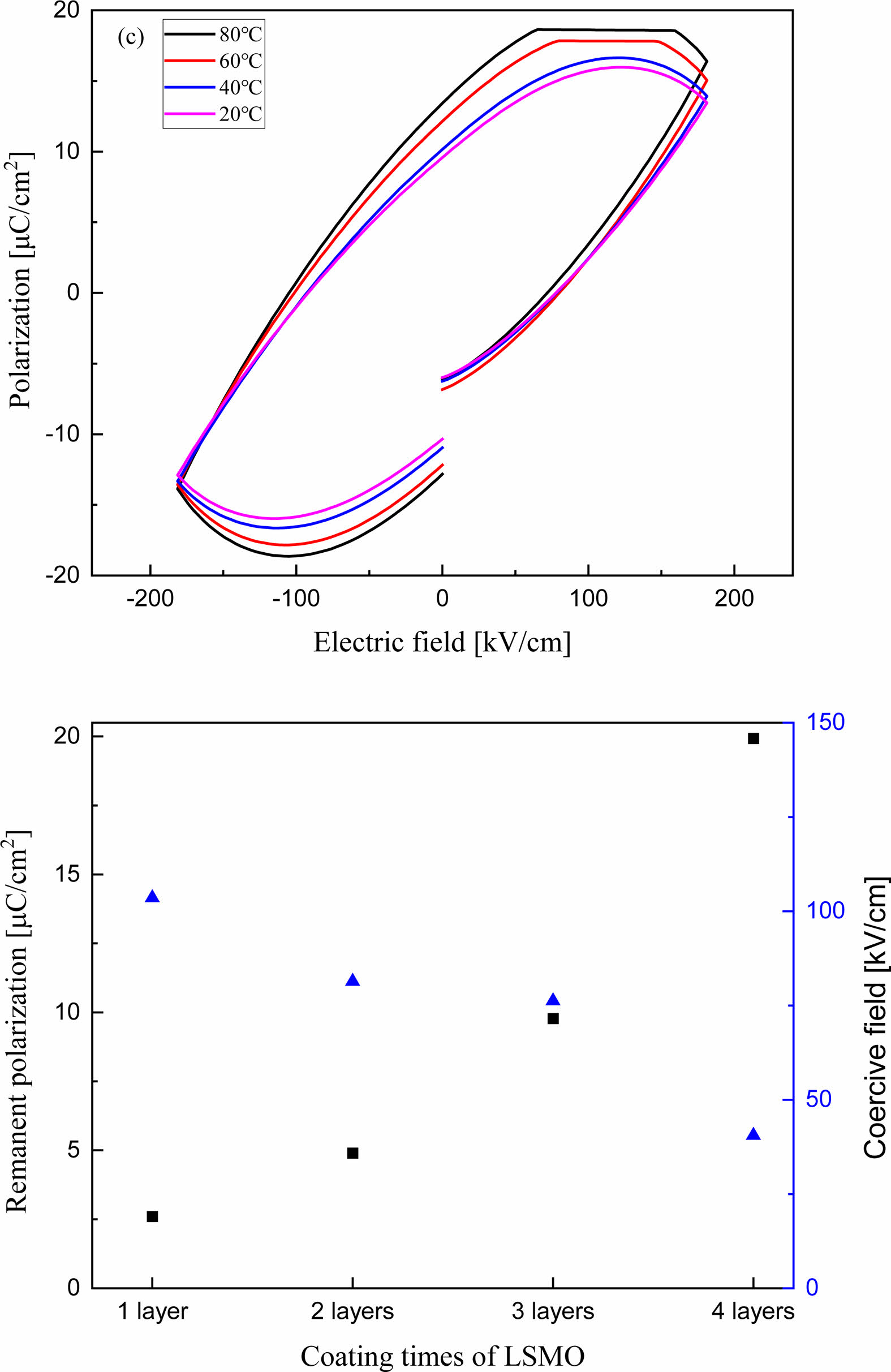
Fig. 5(a) shows the P-E hysteresis curve of the BT/LSMO/BT multilayer film with LSMO coated three times. Remnant polarization and coercive field decrease with increasing the temperature, which can be attributed to the decrease in space charge polarization caused by thermal scattering of space charges and lattices. Fig. 5(b) shows the remnant polarization and coercive field of BT/LSMO/BT multilayer films as a function of the number of LSMO coatings. As the thickness of LSMO layer increases, the remnant polarization increases while the coercive field decreases. This is believed to be attributed to the formation of induced polarization in metallic ferromagnetic LSMO due to the dipole moments of ferroelectric BT and the increased in ion displacement between oxygen anions and Mn4+ ions with a small ionic radius within the MnO6 oxygen octahedra in the LSMO film [17], as discussed in Fig. 4.
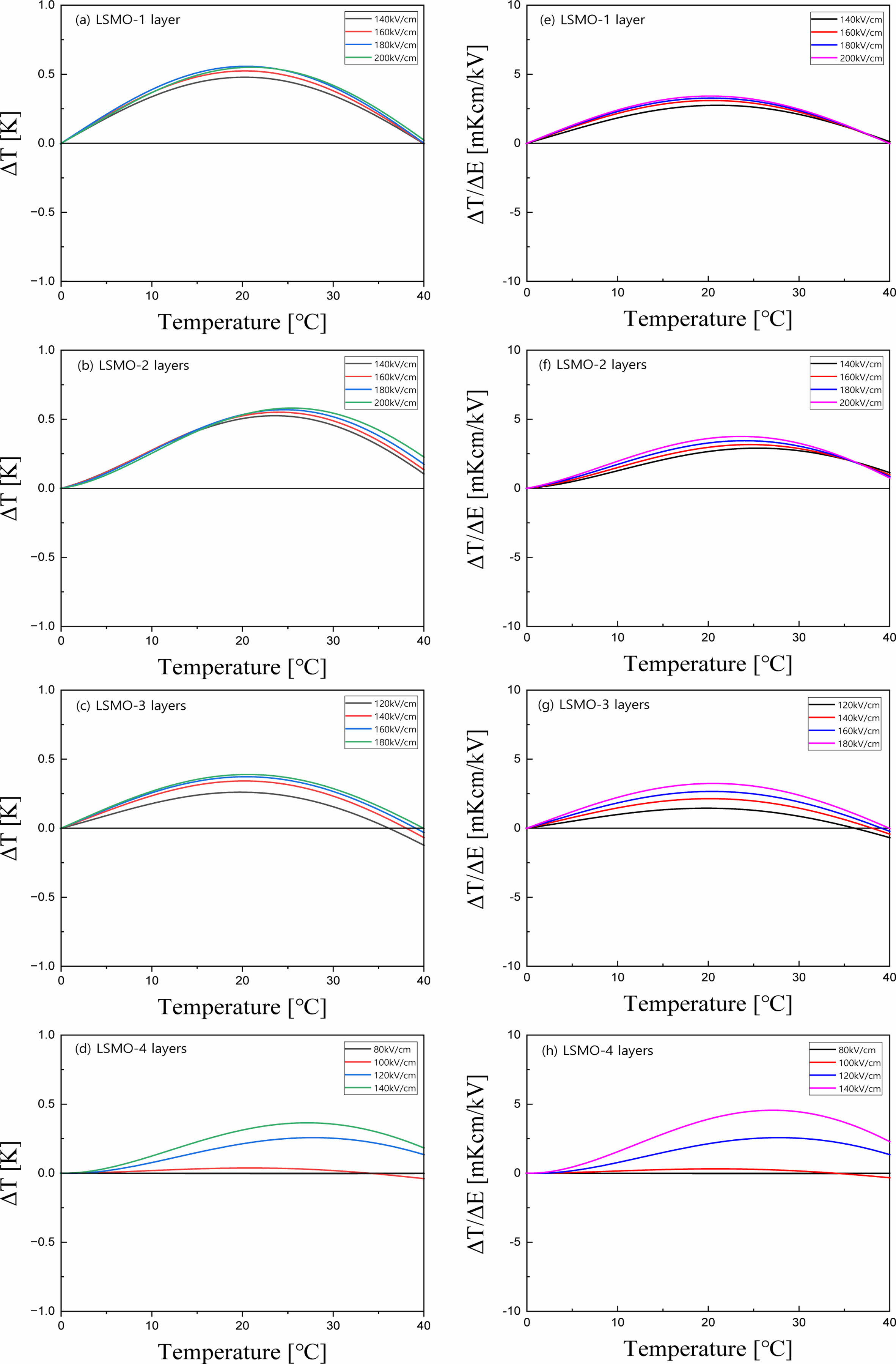
Fig. 6(a-d) shows the EC temperature change (ΔT) of BT/LSMO/BT multilayer films as a function of temperature and applied electric field. ΔT is calculated using the following equation [2]:  , where C is the specific heat and ρ is density. The specific heat and density of BT [18] are 434 J/Kg·K and 6.08 g/cm3, respectively, and those of LSMO [19] are 338 J/Kg·K and 6.44 g/cm3, respectively. In this study, we used these data considering the volume ratio of BT/LSMO/BT multilayer films. In general, the maximum ΔT is observed at temperatures slightly higher than the phase transition temperature, where the domain structure can undergo significant change, resulting in enhanced temperature variation [20]. Additionally, ΔT exhibit a characteristic increase proportional to the applied electric field. It is suggested that in BT/LSMO/BT multilayer films, the space charge polarization and induced polarization increases with applied electric field due to the space charge distribution at the BT/LSMO interfaces and the distribution of Mn4+ ions with a small ionic radius within the oxygen octahedra of LSMO unit cells. The multilayer film coated two-times with LSMO exhibited the highest ΔT of 0.59 K at around 24 oC when a field of 200 kV/cm was applied. This is believed to be due to the high applied voltage per unit thickness and good polarization characteristics. Fig. 6(e-h) shows the EC strength (ΔT/ΔE) of BT/LSMO/BT multilayer films as a function of temperature and applied electric field. The BT/LSMO/BT film, coated with LSMO four times, exhibited the highest ΔT/ΔE of 4.56 mKcm/kV. This can be attributed to the induced polarization due to the ion displacement within the MnO6 oxygen octahedral structure [21], as discussed in Fig. 4.
|
Fig. 2 X-ray diffraction patterns of BT/LSMO/BT multilayer films. |
|
Fig. 3 Surface (a) and cross-sectional (b)-(d) SEM micrographs of BT/LSMO/BT multilayer films. |
|
Fig. 4 Relative dielectric constant according to the temperature (a) and the applied frequency (b) of BT/LSMO/BT multilayer films. |
|
Fig. 5 P-E hysteresis loop (a) and remnant polarization and coercive field (b) of BT/LSMO/BT multilayer films. |
|
Fig. 6 EC temperature change (a-d) and EC strength (e-h) of BT/LSMO/BT multilayer films. |
BT/LSMO/BT multilayer films were fabricated using a chemical solution deposition method, with LSMO positioned between the BT layers. Structural and electrical properties were measured by varying the thickness of the LSMO layer. The XRD intensity of the BT film showed a decreasing trend as the thickness of the LSMO film increased. As the number of coating times, that is thickness, of LSMO increased, the dielectric constant increased. This is attributed to a relatively decrease lattice mismatch and compositional fluctuation at the interface between the BT and LSMO layers. Remnant polarization and coercive field decrease with increasing temperature, which is attributed to a decrease in space charge polarization caused by thermal scattering. In all specimens, the maximum ΔT occurred at temperatures slightly higher than the phase transition temperature. Furthermore, ΔT was observed to increase proportionally to the applied electric field, indicating that polarization increases with the displacement of space charges.
This research was supported by Basic Science Research Program through the National Research Foundation of Korea (NRF) funded by the Ministry of Education (2020R1A6A1A03038697). This work was supported by the National Research Foundation of Korea (NRF) grant funded by the Korea government (MSIT) (2021R1I1A3052426), and the Technology Innovation Program (20020478, Development of commercial reference materials for chemical composition of nano-grade aluminum oxide for rechargeable battery separator coating) funded By the Ministry of Trade, Industry & Energy (MOTIE, Korea).
- 1. P. Kobeko and J. Kurtschatov, Z. Phys. 66[3-4] (1930) 195-205.
-

- 2. A.S. Mischenko, Q. Zhang, J. F. Scott, R.W. Whatmore, and N.D. Mathur, Science 311[5765] (2006) 1270-1271.
-
- 3. X. Wei, C. Zhao, T. Zheng, X. Lv, L. Zhang, B. Li, and J. Wu, Acta Materialia 227 (2022) 117735.
-
- 4. J.E. Lim, M.G. Lee, B.J. Park, S.H. Lee, J.S. Park, Y.G. Kim, and S.G. Lee, J. of Ceram. Process. Res. 23[5] (2022) 583-588.
-
- 5. N. Tanwar, S. Upadhyay, R. Priya, S. Pundir, P. Sharma, and O. P. Pandey, J. of Solid State Chem. 317[1] (2023) 123674.
-
- 6. D. Suastiyanti and Y.N. Maulida, J. Ceram. Process. Res. 22[1] (2021) 61-65.
-
- 7. J. Heremans, J. Phys. D: Appl. Phys. 26[8] (1993) 1149-1168.
-
- 8. Y. Kim, A. Morozovska, and E. Eliseev, Nat. Mater. 13[11] (2014) 1019-1025.
-
- 9. K. Das, P. Dasgupta, A. Poddar, and I. Das, Sci. Rep. 6[3] (2016) 20351.
-
- 10. J.Y. Lim, B.J. Park, S.H. Lee, M.G. Lee, J.S. Park, B.C. Kim, and S.G. Lee, J. Kor. Inst. Electr. Electron. Mater. Eng. 35[5] (2022) 499-503.
- 11. G. Akcay, S.P. Alpay, J.V. Mantese, G.A. Rossetti, Jr. Appl. Phys. Lett. 90[25] (2007) 252909.
-
- 12. M. Kwon, J. Kim, J. Park and S. Lee, J. Ceram. Proc. Res. 21[6] (2020) 725-730.
-
- 13. R.A. Rao, D. Lavric, T.K. Nath, C.B. Eom, L. Wu, and F. Tsui, J. Appl. Phys. 85[8] (1999) 4794-4796.
-
- 14. B. Jaffe, W.R. Cook, and H. Jaffe, Piezoelectric Ceramics, (Academic press, London, 1971) p. 54.
-
- 15. W. Chung and V.C. Lo, Jap. J. Appl. Phys. 45[10R] (2006) 7801-7805.
-
- 16. S.B. Majumder, B. Roy, R.S. Katiyar, and S.B. Krupanidhi, A. Phys. Lett. 79[2] (2001) 239-241.
-
- 17. J. Guo, D. Wang, Y. Han, B. He, N. Zhang, P. Zhang, C. Shi, Y. Chen, M. Ren, Q. Wang, H. Fang, W. Lu, and S. Yan, J. Alloys and Comp. 910 (2022) 164928.
- 18. Y. He, Thermochemica Acta 419[1-2] (2004) 135-141.
-
- 19. M. Saleem and D. Varshney, RSC Adv. 8 (2018) 1600-1609.
-
- 20. H. Maiwa, Jap. J. Appl. Phys. 56[10S] (2017) 10PC05.
-
- 21. B. Neese, B. Chu, S.G. Lu, Y. Wang, E. Furman, and Q.M. Zhang, Science 321[5890] (2008) 821-823.
-
 This Article
-
2023; 24(6): 941-946
Published on Dec 31, 2023
- 10.36410/jcpr.2023.24.6.941
- Received on Jul 18, 2023
- Revised on Sep 19, 2023
- Accepted on Sep 30, 2023
Services
- Abstract
introduction
experimental
discussions and results
conclusion
- Acknowledgements
- References
- Full Text PDF
Shared
Correspondence to
- Sung-Gap Lee
-
aMajor in Ceramic Engineering, School of Materials Science and Engineering, Gyeongsang National University, Jinju 52828, Korea
bDepartment of Materials Engineering and Convergence Technology, Research Institute for Green Convergence Technology, Gyeongsang National University, Jinju 52828, Korea
Tel : +82-10-2686-4427 Fax: +82-55-772-1689 - E-mail: lsgap@gnu.ac.kr
Clean-Energy Research Institute(CRI), Hanyang University, 222, Wangsimni-ro, Seongdong-gu, Seoul, 04763, Korea
E-mail: jcpr@hanyang.ac.kr