


- Optimization of wear properties on LM24 aluminium alloy reinforced with nano alumina and graphite using response surface methodology
R. Surendrana,* and A. Kumaravelb
aDepartment of Mechanical Engineering, Government College of Technology, Coimbatore-641013, India
bDepartment of Mechanical Engineering, K.S.Rangasamy College of Technology, Thiruchengode-637215, IndiaThis article is an open access article distributed under the terms of the Creative Commons Attribution Non-Commercial License (http://creativecommons.org/licenses/by-nc/4.0) which permits unrestricted non-commercial use, distribution, and reproduction in any medium, provided the original work is properly cited.
The dry sliding wear characteristics of metal matrix composites made of LM24 aluminium alloy reinforced with nano alumina (Al2O3) and graphite (Gr) are carried out. The aluminium alloy hybrid composites were prepared by the stir casting technique. In the present study, the wear behaviour of LM24-Al2O3-Gr hybrid composites with various weight percentages of Al2O3 (1, 3 and 5%) with a constant weight of 1% Gr reinforcement are studied. The parameters taken into account of wear bear behaviour of hybrid composites are applied load (10, 20 and 30 N), sliding distance (500, 1000 and 1500 m), sliding speed (200, 300 and 400 rpm) and Al2O3 (1, 3 and 5%) reinforcement. Wear tests are performed using the design of experiments, L27 orthogonal array on pin-on-disc equipment and identified optimising wear parameters in order to minimize the wear rate of LM24-Al2O3-Gr hybrid composites. The uniform distribution of reinforcement particles (Al2O3 & Gr) in the LM24 matrix is ensured by FEMSEM microscopy. The second-order polynomial regression models and the 3D surface plots are generated based on the wear parameters using response surface methodology. A minimum wear rate of 0.0021 mm3/m and a minimum coefficient of friction of 0.141 are observed experimentally
Keywords: LM24 aluminium alloy, Nano alumina, Graphite, Pin-on-disc, FESEM.
Contemporary aluminium-based metal matrix composites (MMCs) are increasingly employed in the aerospace, automotive, and military sectors. Because of their increased strength, stiffness, and wear resistance, aluminium alloys that are incorporated with hard particles are more suitable for wear applications [1]. The importance of the development of metal matrix composites was emphasized by the growth of revenue generated worldwide in the range of 225-350 million USD/year during 2011-2012 [2]. Aluminium alloys are numerous in number and they have specific applications. Among the various aluminium alloys, LM6, A356, AA7075, Al2024, Al6061, Al6063, LM13, LM26 [3], etc., are mostly experimented as a matrix material for MMCs.
Ceramics find valuable applications in wearing surfaces as coatings and claddings [4-6]. Ceramics such as Al2O3, SiC, and ZrB2 find numerous applications in various fields of Engineering including energy systems [7-11]. Particles of steel fibers, Al2O3, SiC, fly ash, TiO2, B4C, Gr, ZrB2, TiC, etc. are used as primary or secondary reinforcement in metal matrix composites [12-14]. As compared to micron-sized reinforcements, nanoparticles impart improved mechanical and wear characteristics of MMCs due to the additional effects of the interaction of particles with dislocations [15]. Aluminium oxide is the preferred ceramic material in the present study. Secondary reinforcements are mostly preferred for imparting specific requirements such as lubrication, damping, machinability, and strength. Researchers are preferred to work with different combinations of matrix materials and reinforcements. Typically, using micron-sized reinforcements, MMCs made of LM25+SiC+Gr [16], LM13+SiC+Gr [17], LM13+Fe [18], Al2024+TiC [19], Az31+ZrO2 [20], Al7075+B4C+ZrB2 [21], AA7075+FA [22], AA6082 T6+Sn+Zn+Gr [23] and Al6061+Al2O3 [24] were analyzed for wear characteristics. However, due to the specific advantages of nano reinforcements, presently the motivation is towards the development of hybrid nanocomposites. Hybrid-reinforced metal matrix composite materials are expected to give superior properties due to their better homogenous microstructure in the matrix [25-29].
Shanmugaselvam et al. [30], MMCs made of aluminium alloy LM4, reinforced with 5% nano alumina and 0.5% Mo resulted in a low wear rate of 0.015 mm3/m under a load of 10 N. Here, the wear rate achieved is very much lower than 0.04 mm3/m which is the value for pure LM4 aluminium alloy. To study the tribological behavior of MMCs made of Al8011 and 15% nano boron carbide, Vinayaga et al. [31] conducted Grey Relational Analysis (GRA) and optimized the input parameters. They achieved a minimum wear rate of 2.451 mm3/min and a minimum coefficient of friction of 0.159. A study on the dry sliding behavior of MMCs made of Al7075, nano TiO2 and Gr was conducted by Danappa et al. [32]. They optimized the input parameters using Response Surface Methodology (RSM) and achieved a minimum wear rate of 0.0002507 mm3/m at a load of 10 N, sliding speed of 600 rpm, sliding distance of 1000 m and 4% nano TiO2. It may be appreciated that the presence of hard TiO2 particles is responsible for exhibiting a very low wear rate.
Paulraj and Harichandran [33] studied the mechanism of wear and morphology of worn surfaces, in the case of MMCs made of AA2024 with Nano SiC and nano h-BN. They could achieve a minimum wear rate of 0.0003 mm3/m with 2% nano SiC and 1.5% nano h-BN under a load of 10 N at room temperature. However, the wear rate has increased to 0.0041 mm3/m at a temperature of 3000 °C. Kumar et al. [34] have investigated that MMCs made of Al2219 with 2% nano B4C and 2% MoS2 have resulted in reduced wear rate when the temperature is increased from 500 °C to 1000 °C. It can be appreciated that the presence of MoS2 is responsible for the development of oxide films and glazing layers on the pin surface, resulting in a reduced wear rate.
It is observed from the literature that, MMCs made of the desired combination of materials need to be tested for the required behavior, without which safety in the utility cannot be ensured. LM24 aluminium alloy is primarily used for thin-walled castings with intricate shapes. It needs to be enhanced with improved wear resistance to house moving parts. Alumina is well known for its superior wear properties. Gr is preferred to impart lubrication in the component. It is concluded from the literature survey that the wear behavior of LM24 aluminium alloy reinforced with nano Al2O3-Gr was not reported. Hence, it is attempted here to study the tribological behavior of MMC made of LM24, nano alumina and Gr. Design of experiments procedure as well as Box Benham technique are employed to achieve the optimum behavior.
The LM24 aluminium alloy is used as a piston material due to excellent tribological properties. LM24 contains the constituents of 0.7-1.5% Cu, 0.8-1.5% Mg, 10.5-13% Si, 1% Fe, 0.5% Mn, 1.5% Ni, 0.5% Zn, 0.1% each of Pb and Zn, 0.2% Ti and the balance being Al. Due to its high degree of hardness and wear resistance, alumina is used as reinforcement material. Gr is also used as a reinforcement material due to its unique lubricant properties. Ingots of LM24 and 50 mu-sized Gr were procured from Coimbatore Metal Mart, Coimbatore. Alumina nano powder has been procured from MK Nano, Canada.
Stir Casting Technique
To achieve the superior properties of MMCs for tribological studies, the stir casting technique [21, 35] is preferred to make LM24-Al2O3-Gr hybrid composites due to its low manufacturing cost with high quality composites. LM24 aluminium alloy was used a matrix material for manufacturing hybrid composite material. The Al2O3 nanoparticles and Gr were used as a reinforcing material. The reinforcement of The small pieces of LM24 aluminium alloy were placed in a graphite crucible and it was melted in electrical resistance furnace at 800 oC. The Al2O3 nanoparticles and Gr were preheated to 300 oC for 10 min in a muffle furnace to remove the impurities. The Al2O3 nanoparticles (various Wt. % viz. 1%, 3% and 5%) and Gr (1% in wt.) were added through the hopper arrangement to the molten aluminium alloy material during the formation of vortex in the melt via mechanical stirring. The molten metal is stirred at 200 rpm for 5 minutes at 760 °C before being put into the warmed metallic die. The cast component is solidified at room temperature before being taken out from the die.
Microstructural Characterization
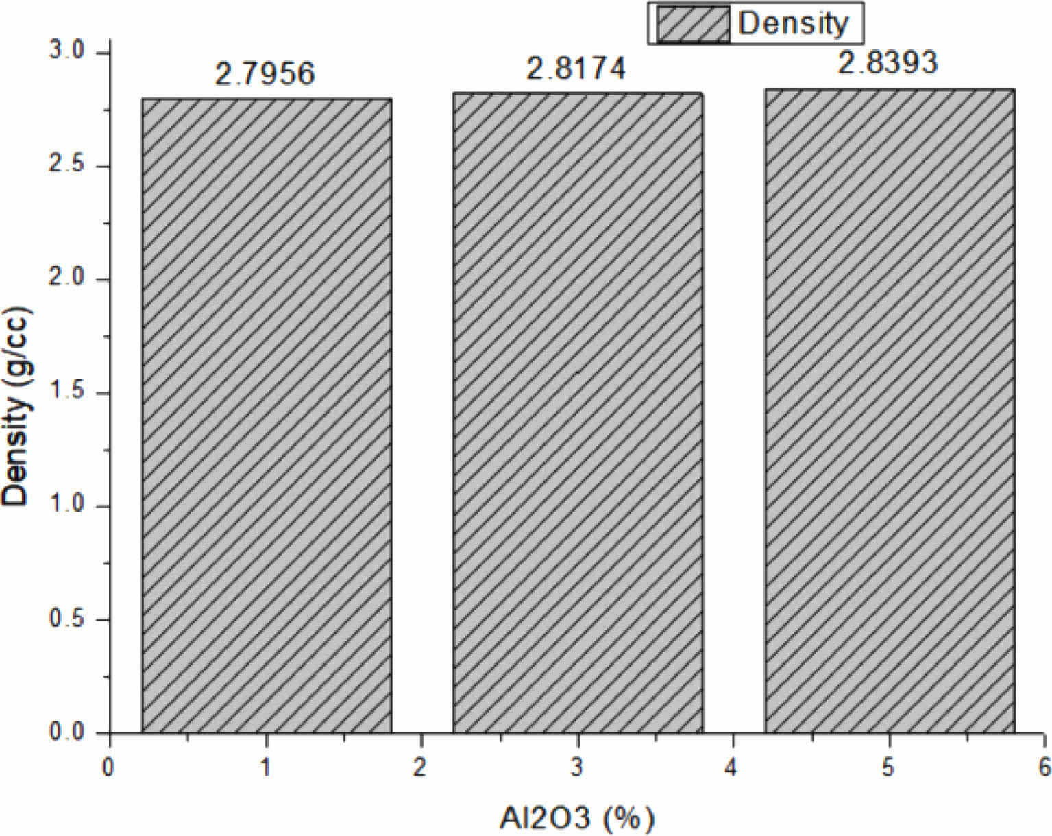
Few samples of cast pieces were cut into cube of size 10 mm and subjected to micro structural investigation. These composite specimens were polished using emery papers grade range from 500 to 2000. The specimens were etched with Keller’s reagent after polishing. Microstructural characterization is carried out using Field Emission Scanning Electron Microscope (FESEM) (Model: RA-ZEI-001, Carl Zeiss of Microscopy). The densities of hybrid MMCs are calculated using “rule of mixture”. Fig. 1 shows the density values of composite samples with reinforced wt. % viz. 1%, 3% and 5% of Al2O3 nanoparticles are 2.7956 g/cc, 2.8174 g/cc and 2.8393 g/cc respectively.
Wear Studies
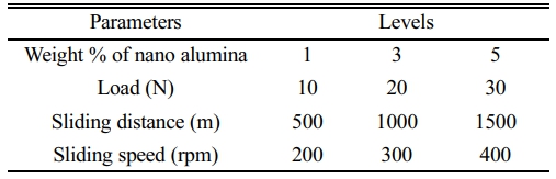
The friction and wear testing was carried out with the help of pin-on-disc tribometer (Make: DUCOM). All tests were carried out under dry sliding conditions at room temperature of 25±2 oC. The specimens to be wear tested are prepared as per ASTM G99 Standard. The pin wear test specimens of f 10 mm and length 30 mm were prepared using wire cut EDM machine. The disc of pin-on-disc setup is a counter face material with 100 mm in diameter and made of EN31 steel hardened to 60 HRC. The composition of disc material: C1.08%, Si 0.25%, Mn 0.53%, S 0.015%, P 0.022%, Ni 0.33%, Cr 1.46% and Mo 0.06%. Considering the 4 input parameters such as % weight of nano alumina, load, sliding distance and sliding speed, and their 3 levels of variations, the values of parameters are presented in Table 1. The values of input parameters have been chosen from literature involving similar studies. Typically, the loads have been chosen based on the reference [12] who performed their studies in the load range 10N to 40 N.
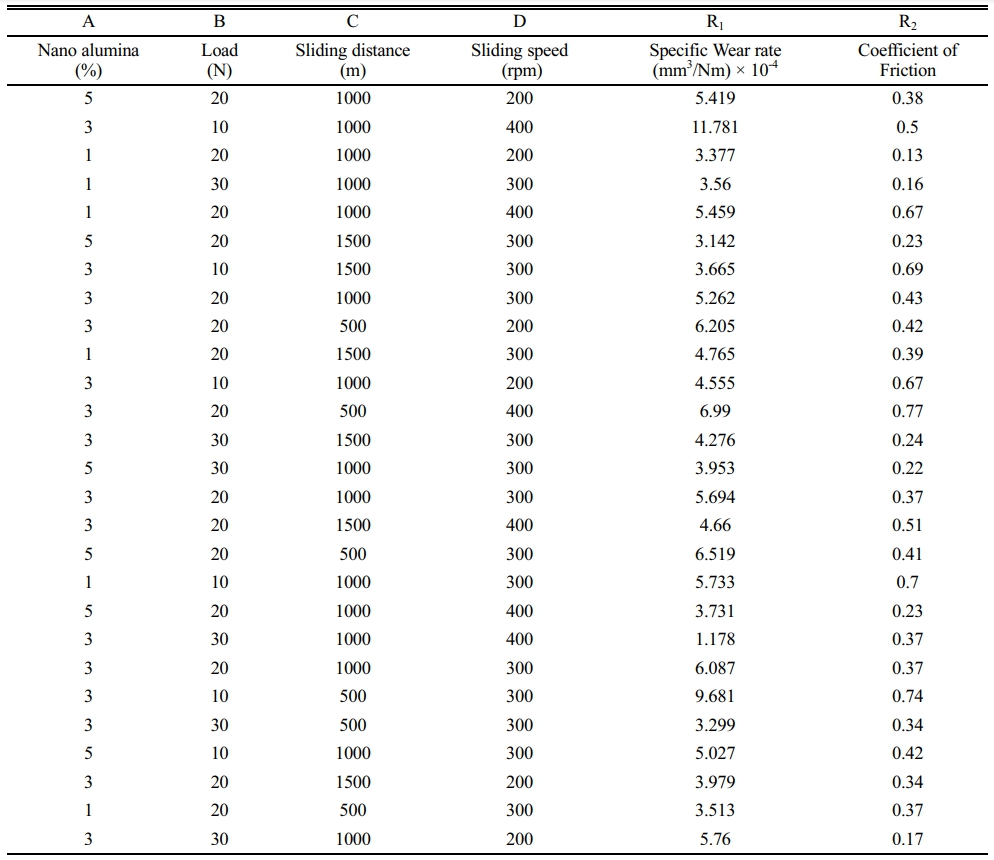
81 experiments are needed, if all the above parameters are combined in all possibilities. In order to reduce the number of experiments and to study the full range, design of experiments procedure is applied. Accordingly, the L27 array is prepared using “Design Expert” software and it is listed in Table 2. The specimen is made contact against the rotating disc, the disc causes sliding wear on the specimen. The surface finish of flat surfaces of both pin specimens and the rotating disc were maintained about 0.4 mm. The sample specimens were thoroughly cleaned by acetone and dried before carrying out of each wear test.
|
Fig. 1 Density of LM24-Al2O3-Gr hybrid composites. |
Microstructural Analysis
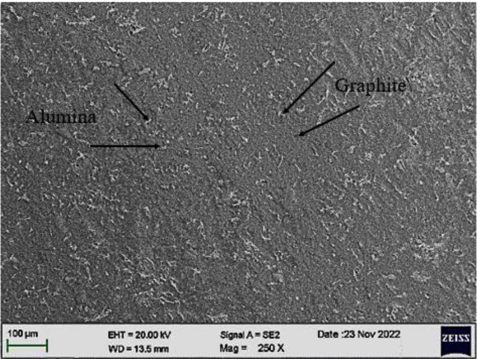
The microstructure of LM24 aluminium alloy reinforced with Al2O3 nanoparticles (3% in wt.) and Gr (1% in wt.) is shown in Fig. 2. The Al2O3 nanoparticles and Gr particles were uniformly distributed in LM24 aluminium matrix as fine precipitates. Proper stirring achieves homogeneous and refined microstructure through stir casting method.
Response surface methodology
With 4 input variables and 3 levels, it is impossible to make any decision on the performance just with 27 experiments. The outputs in the present study are specific wear rate and the coefficient of friction. When the number of outputs is more than 1, techniques such as multi-response optimization [36] are employed. Hence it is resorted to the design of experiments (DOE) using the Response Surface Methodology (RSM) and to optimize the input parameters for minimizing the specific wear rate and the coefficient of friction. Box-Behnken method is one of the most preferable method in RSM. It comprises of modules for design of experiments, ANOVA, framing the regression equations and computation of the optimum values. Software such as Design Expert which incorporate such methods are capable of presenting the outputs in numerical as well as graphical forms. 27 experiments have been conducted and the results of specific wear rate and coefficient of friction have also been included in Table 2. Specific wear rate is defined as the volume of material dislodged in cubic mm per unit load in N and for unit sliding distance in metre. The Coefficient of friction is a dimensionless quantity which is defined as the ratio of friction force to the normal reaction [37].
Wear Studies
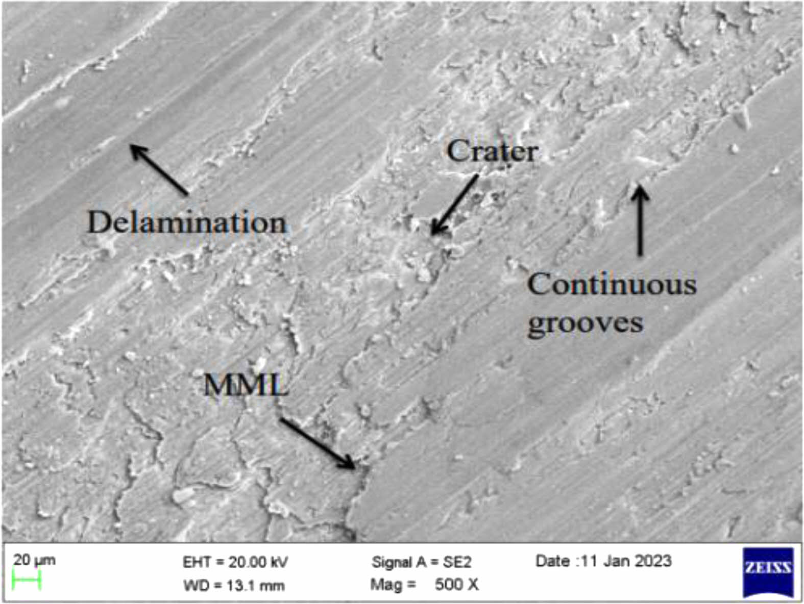
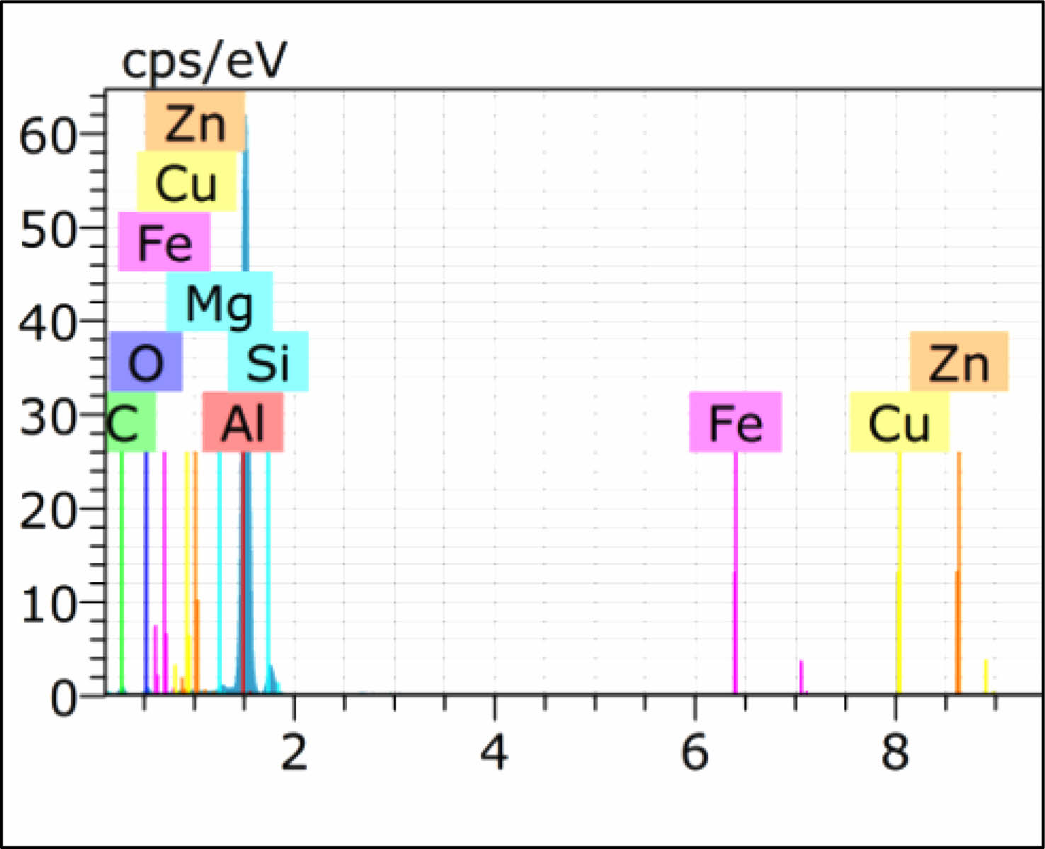
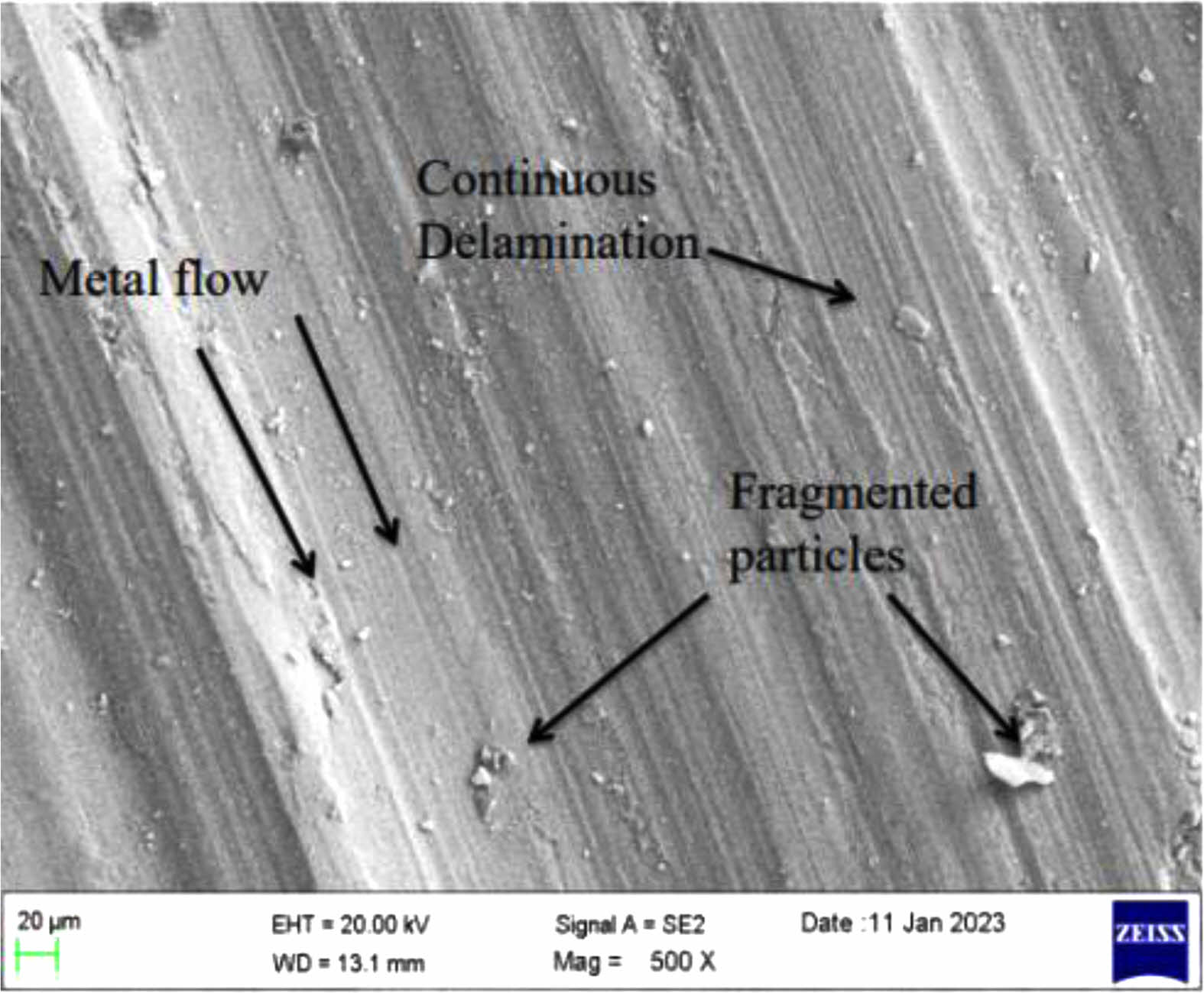
Figure 3 shows the wear surface of MMCs with 1% nano alumina and 1% Gr reinforcement, for wear test carried out under applied load of 20 N, distance of 500 m and disc speed of 300 rpm. Continuous grooves, crater and delamination were observed on the worn-out surface. The observed Mechanical Mixed Layer (MML) is made up of a solid lubricant formed by transfer of material from counter face to the wear surface. Formation of MML is almost a common behaviour while subjecting aluminium alloys to wear test by sliding against ferrous alloys. Shifting and combination of materials from both the rubbing surfaces under favourable conditions of load and speed is the cause for this phenomenon. Stojanovic et al. [38] and Shetty et al. [39] have described this phenomenon in detail. Adhesive wear is also found on the surface significantly. Fine scratches are found but no fragments found. EDS analysis as shown in Fig. 4, reveals such a phenomenon showing higher concentration of Fe. EDS also shows the major constituents such as Aluminium, Magnesium, Silicon and Zinc. Fig. 5 shows the micrographs for the MMC of LM24 with 3% nano alumina and 1% Gr under the load of 20 N. Fragmented particles are significant and this is due to heavier loads as indicated by Stojanovic et al. [38].
Regression equations and graphical solutions
After conducting 27 experiments as per the DOE, it becomes necessary to employ RSM [40] to identify the correlations between the input factors and the output responses [41]. The software is made generate 100 simulated solutions. Here, the input variables are weight % nano alumina (A), load (B), sliding distance (C), and sliding speed (D) and the output responses are specific wear rate (R1) and coefficient of friction (R2). The numerical analysis performed by Aswathi et al. [43] gives a better insight into the variables used. Using “Design expert” software, second order polynomial regression models have been generated using for the specific wear rate and the coefficient friction.

The above regression equations are useful to compute the output responses namely specific wear rate and the coefficient of friction for the specified input variables. The linear effect is shown by the first four terms, the higher order effect is indicated by the last four terms, and the interaction effect is indicated by the six terms in between. The correctness of the regression model is to be confirmed with the values of R2, and p. The significance test yielded R2 and modified R2 values of 94.42% and 87.92% respectively for specific rate of wear. For the coefficient of friction, R2 and modified R2 values have been 93.33% and 85.55%. Closeness of R2 and modified R2 values indicate the validity of the model generated. In the regression model for the specific wear rate, p<0.0001 for the load and as well as the interaction term between load and sliding speed. It indicates that these factors are more significant in affecting the specific wear rate. In the case of coefficient of friction, the load p<0.0001. Hence the load is the most influencing factor for coefficient friction. Lack of fit are 26.91% and 18.46% for the specific wear rate and the coefficient of friction respectively which are nonsignificant. Hence the models are fit. The regression model works with a confidence level of 95%.
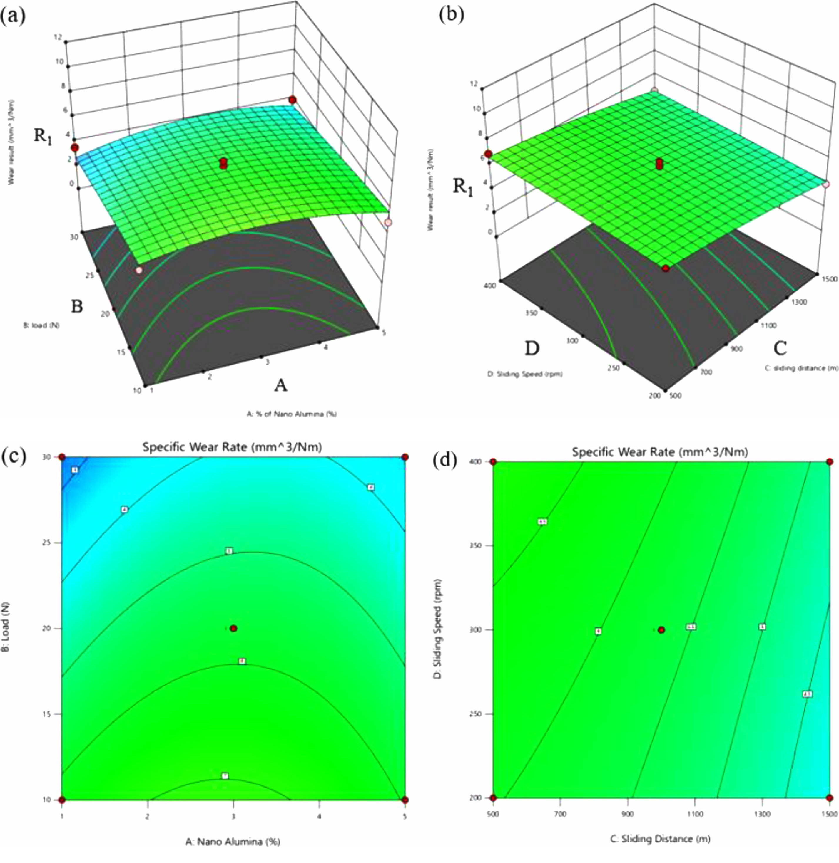
Combining any two variables while keeping other variables constant at mid values, surface plots have been generated for the specific wear rate as well as coefficient friction. This means that each surface plot shows either wear (R1) or friction force (R2) against any two input variables from A (% nano alumina), B (load in N), C (sliding distance in m) and D (sliding speed in rpm). Fig. 6(a) is 3D surface plot for wear (R1) against wight % nano alumina (A) and load (B), keeping sliding distance (C)=1000 and sliding speed (D)=300 rpm constant. It can be observed that at the minimum load, wear is minimum for minimum and maximum values of weight % nano alumina. Fig. 6(b) is 3D surface plot for wear (R1) against sliding distance (C) and sliding speed (D), keeping weight % of nano alumina (A)=3 and load (B)=20 N constant. At minimum speed wear rate is minimum for minimum and maximum sliding distance. Figs. 6(c) and 6(d) are 2D plots corresponding to Figs. 6(a) and 6(b) respectively. Specific wear rate trend can not be said with reference to one variable. Typically, at the minimum load, wear is minimum for minimum and maximum values of weight % nano alumina at fixed values of sliding distance 1000 m and sliding speed 300 rpm as evident from Fig. 6(c). Moreover, it increases with reduction of sliding distance but at different rates depending on the speed as evident from the slopes of curves in Fig. 6(d).
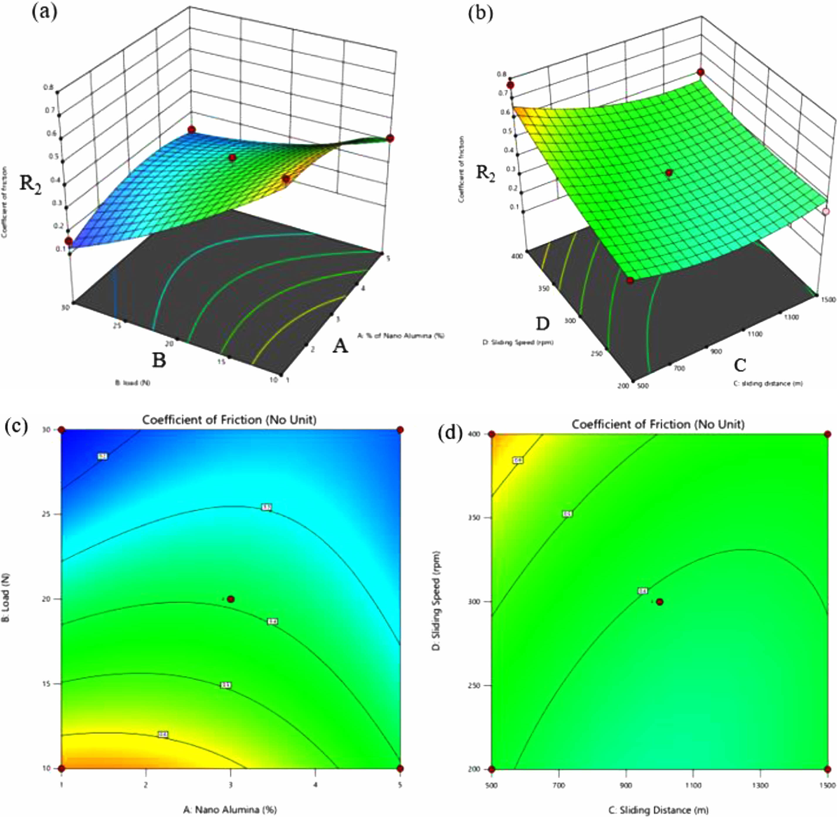
Fig. 7(a) is 3D surface plot for coefficient of friction (R2) against % nano alumina (A) and load (B), keeping sliding distance (C)=1000 and sliding speed (D)=300 rpm constant. It can be observed that for the minimum weight % of nano alumina and maximum load, friction force is minimum. Fig. 6(b) is 3D surface plot for coefficient of friction (R2) against sliding distance (C) and sliding speed (D), keeping wight % of nano alumina (A)=3 and load (B)=20 N constant. For minimum speed, friction force is reduced for maximum and minimum sliding distance. Figs. 7(c) and (d) are 2D plots corresponding to Figs. 7(a) and (b) respectively. 2D plots are better viewed for studying the trends of output variables with reference to the input variables.
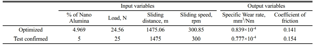
From the multiple simulated results, the Design Expert software has optimized the input parameters as 4.969 weight % of nano alumina, load 24.564 N, sliding distance 1475.064 m and sliding speed 300.846 rpm. The confirmation test gave a specific wear rate of 0.777×10⁻⁴ mm3/Nm against the predicted value of 0.839×10⁻⁴ mm3/Nm. The test value of specific wear rate is equivalent to 0.0021 mm3/m which is considerably less than 0.0033 mm3/m achieved by Radhika and Subramanian [43] in their studies with MMC made of Aluminium, alumina and Graphite in micron sizes. Moreover, the predicted optimum value of coefficient of friction is 0.141 and the corresponding test confirmed value is 0.154. The coefficient of friction achieved in the present study is considerably less than 0.324 which is reported in [43]. The positive effect of nano alumina in the developed MMC is significant. Table 3
|
Fig. 2 FESEM micrograph of LM24-3% Al2O3-1%Gr |
|
Fig. 3 FESEM of surface subjected to mild wear. |
|
Fig. 4 EDS of MMC with 1% nano alumina and 1% Gr. |
|
Fig. 5 FESEM of surface subjected to severe wear |
|
Fig. 6 (a) 3D surface plot for specific wear rate (R1) vs weight % of nano alumina (A) and load (B); |
|
Fig. 7 (a) 3D surface plot for coefficient of friction (R2) vs weight % of nano alumina (A) and load (B); |
To explore the tribological behavior of MMC made of LM24 with nano alumina and Gr, the specimens have been stir cast and the distribution of reinforcements has been confirmed by FESEM. The specimens have been tested by a computerised pin-on-disc machine. As there are four input variables and three levels of variations, the design of experiment procedure has been used to form the L27 array. 27 experiments have been conducted and the results of FESEM and EDS analysis show the formation of MML in the hybrid nano MMC made with LM24, 3 weight % nano alumina and 1 weight % graphite. MML improves tribological behaviour. The micrograph shows very little agglomeration and little clustering of particles at the grain boundaries. With the input parameters and the output responses, second-order polynomial regression models have been generated for the specific wear rate and the coefficient of friction using RSM. 3D surface plots have been generated for both the output responses. Further, the Box-Behnken method of optimization has been performed to optimize the input parameters which results in minimum values of wear rate, 0.0021 mm3/m and coefficient of friction 0.154 which are lower than those of literature values corresponding to MMC made of Aluminium, micro alumina and Gr. This observation signifies the improved effect of nano alumina over micro alumina.
The author would like to thank the All India Council for Technical Education (AICTE), New Delhi for the equipment support (Grant No: 9 - 240/IDC/MODROB/Policy - 1 / 2019 - 20 dt. 20.07.2020) under MODROB Scheme.
- 1. M. Surappa, Wear 265[3-4] (2008) 349-360.
-

- 2. C.O. Ujah and D.V.V. Kallon, Crystals 12[10] (2022) 1357.
-
- 3. P. Kumaravel, K. Venkatesh Raja, and P. Suresh, J. Ceram. Process. Res. 24[3] (2023) 569-577.
-
- 4. A. Alraisi, Y. Yi, Suwon Lee, Saeed A. Alameri, Maryam Quasem, Chan-Young Paik, and Changheui Jang, Annals of Nuclear Energy 165[108784] (2022) 1-13.
-
- 5. A. Alameri and A.K. Alkaabi, Nuclear Reactor Technology Development and Utilization, (2020) 27-60.
-
- 6. A. Alameri and M. Alrwashdeh, Annals of Nuclear Energy 163[108551] (2021) 1-8.
-
- 7. M. Alrwashdeh and S. A. Alameri, Nuclear Science and Engineering 194[2] (2019) 163-167.
-
- 8. M. Alrwashdeh and S.A. Alameri, Energies 15[3772] (2022) 1-17.
-
- 9. M. Alrwashdeh and S.A. Alameri, Energies 15[8008] (2022) 1-16.
-
- 10. M. Ali, A.K. Alkaabi, Saeed A. Alameri, and Yacine Addad, Int. J. Exergy 36[1] (2021) 98-122.
-
- 11. S.A. Alameri and A.K. Alkaabi, Trans. American Nuclear Society 118 (2018) 693-695.
- 12. S.J.S. Chelladurai, S.S. Kumar, Narasimharaj Venugopal, Abhra Pradip Ray, T.C. Manjunath, and S. Gnanasekaran, Materials Today: Proceedings 37 (2021) 908-916.
-
- 13. S. Vinothkumar and P. Senthilkumar, J. Ceram. Process. Res. 23[4] (2022) 546-552.
-
- 14. R. Santhanakrishnan, V.S. Thangarasu, R. Arravind, and V. Ramachandiran, J. Ceram. Process. Res. 24[1] (2023) 174-181.
-
- 15. R. Casati and M. Vedani, Metals 4[1] (2014) 65-83.
-
- 16. S. Suresha and B. Sridhara, Materials & Design 31[4] (2010) 1804-1812.
-
- 17. J.P. Kumar and D.R. Smart, Materials Today: Proceedings 46 (2021) 8172-8179.
-
- 18. V. Abouei, H. Saghafian, S.G. Sabhestari, and M. Zarghami, Materials & Design 31[7] (2010) 3518-3524.
-
- 19. E. Bedolla-Becerril, J. Garcia-Guerra, V.H. Lopez-Morelos, M.A. Garcia-Renteria, L.A. Falcon-Franco, V. H. Martinoz-Landeros, S. Garcia-Villareal, and S.E. Flores-Villasenor, Coatings 13[1] (2022) 77.
-
- 20. K.K. Basha, R. Subramanian, T. Sathishkumar, and G. Suganya Priyadharshini, Materials & Technologies 57[3] (2023).
-
- 21. P. Sathiamurthi, K.S. Karthi Vinith, A. Sivakumar, and N. Bagath Singh, J. Ceram. Process. Res. 24[3] (2023) 429-438.
-
- 22. B. Thamaraikannan, A. Sagai Francis Britto, S. Senthilraja, and R. Rajkumar, J. Ceram. Process. Res. 24[3] (2023) 415-421.
-
- 23. C. Ramesh, Mohanraj Chandran, K. Chellamuthu, and A. Sivakumar, J. Ceram. Process. Res. 24[1] (2023) 120-126.
-
- 24. A. Bhat, G. Kakandikar, A. Deshpande, A. Kulkarni, and D. Thakur, Material Science, Engineering and Applications 1[1] (2021) 11-20.
-
- 25. P. Yadav, A. Ranjan, H. Kumar, A. Mishra, and J. Yoon, Materials 14[21] (2021) 6386.
-
- 26. P. Satiskumar and N. Natarajan, J. Ceram. Process. Res. 23[3] (2022) 383-390.
-
- 27. T. Siva and K. Anandavelu, J. Ceram. Process. Res. 24[2] (2023) 406-414.
-
- 28. C. Sailaja, K.T. Thilagham, K.T. Anand, P. Ganeshan, Sathish Kannan, A.H. Seikh, and A. Ghosh, J. Ceram. Process. Res. 24[4] (2023) 617-625.
-
- 29. B. Somasundaram, K.T. Anand, D. Kirubakaran, P. Ganeshan, Sathish Kannan, A.H. Seikh, and A. Ghosh, J. Ceram. Process. Res. 24[4] (2023) 626-633.
-
- 30. P. Shanmugaselvam, J.R. Yogaraj, et al., Materials Today: Proceedings 37 (2021) 844-848.
-
- 31. N. Vinayaka, K.G.J. Christiyan, S. Shreepad, S.N. Pathi, S.G. Dhambhare, Ranjit kumar Puse, K. Gayathri, A.B. Kolekar, and S. Nagarajan, Journal of Nanomaterials 2023 (2023) 1-9.
-
- 32. G. Danappa, C. Raghavendra, R.P. Samy, and K. Naik, Materials Today: Proceedings 38 (2021) 2797-2802.
-
- 33. P. Paulraj and R. Harichandran, Journal of Materials Research and Technology 9[5] (2020) 11517-11530.
-
- 34. N.G.S. Kumar, R. Suresh, and G.S.S. Shankar, Composites Communications 19 (2020) 61-73.
-
- 35. K.M. Senthilkumar, A. Sivakumar, R.M. Shivaji, S.K. Tamang, and M.Giriraj, J. Ceram. Process. Res. 23[2] (2022) 233-236.
-
- 36. N. Ravikumar, R. Vijayan, and R. Viswanathan, J. Ceram. Process. Res. 24[1] (2023) 142-152.
-
- 37. A. Kanakaraj, R. Mohan, and R. Viswanathan, J. Ceram. Process. Res. 23[3] (2022) 268-277.
-
- 38. B. Stojanovic, M. Babic, N. Milarodovic, and S. Mitrovic, Materials and Technology (2015).
- 39. R. Shetty, J. Hindi, B.M. Gurumurthy, A. Hegde, Y.M. Sivaprakash, S. Sharma, A. Amarmurthy, and K. Muralishwara, Cogent Engineering 10[1] (2023) 2200900.
-
- 40. S. Vettivel, N. Selvakumar, R. Narayanasamy and N. Leema, Materials & Design 50 (2013) 977-996.
-
- 41. A.A. Narayanan and R. Sudheesh, Materials and Technology 55[6] (2021) 799-807.
-
- 42. A.A. Narayanan and R. Sudheesh, Materials and Technology 56[3] (2022) 315-322.
-
- 43. N. Radhika and R. Subramaniam, Industrial Lubrication and Tribology 65[3] (2013) 166-174.
-
 This Article
-
2023; 24(5): 899-906
Published on Oct 31, 2023
- 10.36410/jcpr.2023.24.5.899
- Received on Aug 27, 2023
- Revised on Oct 8, 2023
- Accepted on Oct 15, 2023
Services
- Abstract
introduction
materials
methods
results and discussions
conclusions
- Acknowledgements
- References
- Full Text PDF
Shared
Correspondence to
- R. Surendran
-
Department of Mechanical Engineering, Government College of Technology, Coimbatore-641013, India
- E-mail: surendran_r@gct.ac.in, kumaraveliitm@yahoo.com
Clean-Energy Research Institute(CRI), Hanyang University, 222, Wangsimni-ro, Seongdong-gu, Seoul, 04763, Korea
E-mail: jcpr@hanyang.ac.kr