


- Structural, magnetic properties of nickel-substituted strontium W-type ferrites
Jinsong Li, Xiubin Zhao and Ailin Xia*
School of Materials Science and Engineering, Anhui University of Technology, Maanshan 243002, China
This article is an open access article distributed under the terms of the Creative Commons Attribution Non-Commercial License (http://creativecommons.org/licenses/by-nc/4.0) which permits unrestricted non-commercial use, distribution, and reproduction in any medium, provided the original work is properly cited.
Nickel substituted W-type strontium ferrites Sr0.9Ce0.1Zn2-xNixFe16O27 (x=0.0, 0.2, 0.4, 0.6, 0.8 and 1.0) were prepared by a ceramic method. The specimens exhibited a single-phase W-type structure when the Ni content (x) is 0 ≤ x ≤ 1. With the increasing content of nickel dopant, the particles exhibited a hexagonal plate-like shape. The saturation magnetization and remanent magnetization increased x from 0.0 to 0.6, then decreased with x > 0.6. The coercivity of specimens increased gradually for x ≤ 0.2 and then began to decrease from x = 0.3; the coercivity shows a downward trend with the Ni content continuing to increase. Subsequently, as the Ni content increases, there is a downward trend compared to the unsubstituted specimens
Keywords: W-type ferrite, Ceramic method, Structure, Magnetic properties
As a crucial functional material, magnetic ferrites can be divided into three categories: spinel, garnet and magneto plumbite-type. According to the different characteristics of crystal structure, the magneto plumbite-type ferrites are further divided into six types: M, W, X, Y, Z and U [1-3]. The W-type ferrites have both complex magnetic properties and high-frequency soft magnetic characteristics. Due to the high saturation magnetization (Ms) and the excellent chemical stability, W-type ferrites are used in microwave equipment and electromagnetic wave absorbers [4]. The chemical composition formula of W-type ferrites is AMe2Fe16O27. W-type ferrites belong to the hexagonal crystal system. The unit cell is composed of SSRS*S*R* stacking sequences, which can also be seen as the stacking of M-type “SR blocks” and spinel “S blocks” or the addition of an “S blocks” between two “R blocks” in the M-type structure. The iron ions can be located in seven different lattice positions [4, 5].
Different preparation methods for Sr ferrites have been proposed, such as the sol-gel [6, 7], chemical co-precipitation [8], ceramic method [9], and glass crystallization technique [10]. In the study of W-type ferrites, the ceramic method is widely used to achieve mass production due to their simple manufacturing process, stoichiometric composition, controllable grain size, rich raw materials and low price.
Theoretically, the Ms of W-type ferrite is about 10% higher than that of M-type ferrite, while their anisotropic magnetic field is almost the same. Moreover, the W-type ferrite has two kinds of cationic crystal sites, which can be replaced by the various bivalent or trivalent cations, which can tailor the magnetism in a broader range compared with M-type ferrite [11, 12]. Tang et al. [9] prepared BaCoxFe2-x W-type ferrites by a ceramic method. It was found that the magnetic anisotropy field of specimens decreased with the increase of Co content. Akhter et al. [13] used a sol-gel auto combustion method to synthesize CaPb2-xYbxFe16O27 W-type ferrites. They found that the AC conductivity and the natural/imaginary parts of the dielectric constant exhibited an increasing and a decreasing behavior with the increase of dopant content, respectively. The microstructure and magnetic properties of Mg-Cu substituted BaMg2-xCuxFe16O27 prepared by the ceramics process have been discussed by Niu et al. [14]. The lattice constant increased with the increase of Cu content (x), while the lattice constant c decreased. Ghasemi [15] reported highly magnetized SrCo2-xMnxFe16O27 (x = 0-0.5) W-type ferrites prepared by a coprecipitation route. The magnetization reversal mechanism of the specimen followed the Stoner Wohlfarth mechanism, and the domain wall motion mechanism was also discussed.
However, the effect of nickel substitution on the magnetic properties of strontium W-type ferrite synthesized by the ceramic method was still not reported. Therefore, in this study, the W-type ferrite Sr0.9Ce0.1Zn2-xNixFe16O27 (x is from 0.0 to 1.0 with the steps of 0.2.) magnetic powders were prepared by ceramic method, and the effects of the nickel content (x) on the structure and the magnetic properties of W-type ferrites Sr0.9Ce0.1Zn2-xNixFe16O27 are systematically studied.
Materials
The starting materials of Fe2O3 (99.2% purity), SrCO3 (98% purity), CeO2 (99% purity), ZnO (99% purity) and NiO (99% purity) powders were used without further purification in this study.
Preparation of W-type ferrites Sr0.9Ce0.1Zn2-xNixFe16O27 powders
150 g specimens with the nominal composition of Sr0.9Ce0.1Zn2-xNixFe16O27 (x is from 0.0 to 1.0 with 0.2 steps) were obtained via a conventional ceramic method. Then, the mixed powders were ball-milled with steel balls of a diameter of 6 mm for 4 hours, using water as the disperser. The slurry obtained was dried and pressed into some small pieces, and then calcined at 1300 ℃ in a muffle furnace for 2 hours in the air atmosphere. Afterwards, the calcined pieces were crushed by a vibrator to prepare specimen powders through a 100-mesh sieve.
Characterization
The phase composition of specimens was obtained by an X-ray diffractometer (XRD, PANalytical X’Pert Pro) using Cu Kα (λ=1.5406 Ǻ) radiation. The scanning range is between 20° and 80° with the steps of 0.01°. A field emission scanning electron microscope (FESEM, HITACHI S-4800) was used to measure the morphologies of specimens. A vibrating sample magnetometer (VSM, MicroSense EZ7) was used to measure the RT magnetic properties at a maximum external field of 20,000 Oe.
Structure and morphology
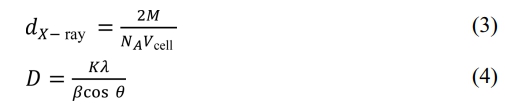
Fig. 1 shows the XRD patterns of obtained specimens. Compared with all the peaks in the standard JCPDS card XRD patterns (PDF#00-052-1860), no other impurity peaks were found in Fig. 1, indicating the single phase W-type structures in all the specimens. From Fig. 1, it can be seen that Ni2+ ions entered into the lattice without forming any other phase.
The lattice parameters a and c can be calculated from the values of dhkl corresponding to (116) and (1010) peaks and the following equations (1) and (2) [16, 17]:
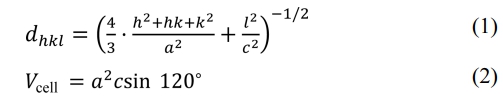
where α and c are lattice constants; h, k and l are the Miller indices. dhkl and Vcell are the crystal face spacing and the cell volume, respectively. The following equations (3) and (4) were used to calculate the X-ray density (dX-ray) and the average crystallite size (D) [18, 19], respectively.
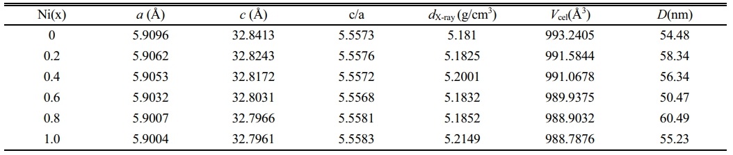
where NA, K and λ are 6.02×10²³, 0.89 and 1.5406 Ǻ, respectively; M, β and θ are the molar mass, the full-width at half-maximum and the Bragg’s diffraction angle, respectively. The values calculated by the above formulas are listed in Table 1.
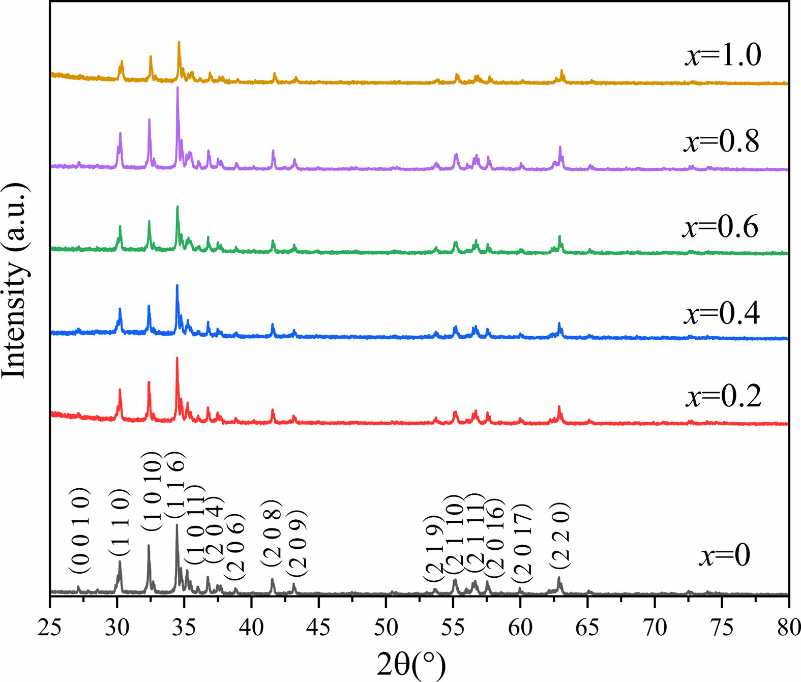
Fig. 2 shows the dependency of lattice constants a and c on x. It can be seen that with an increase of x from 0.0 to 1.0, both the lattice constants a and c show a decreasing trend. The lattice parameter a changes slightly, while the lattice parameter c decreases obviously from 32.8413 Å (x=0.00) to 32.7961 Å (x=1.0). The change of lattice parameters caused by ion substitution has also been reported in early literature [20-25]. It is well-known that the ionic radii of Zn2+ and Ni2+ are 0.82 and 0.78 Å, respectively [26]. As a result, after replacing Zn2+ with Ni2+, the lattice parameters a and c become smaller in the specimens. Therefore, lattice deformation was caused by the Ni2+ substitution. In this study, with the increasing amount of Ni substitution, the lattice parameters decreased, resulting in a decrease of dhkl, which exhibits the similar change of Vcel as listed in Table 1.
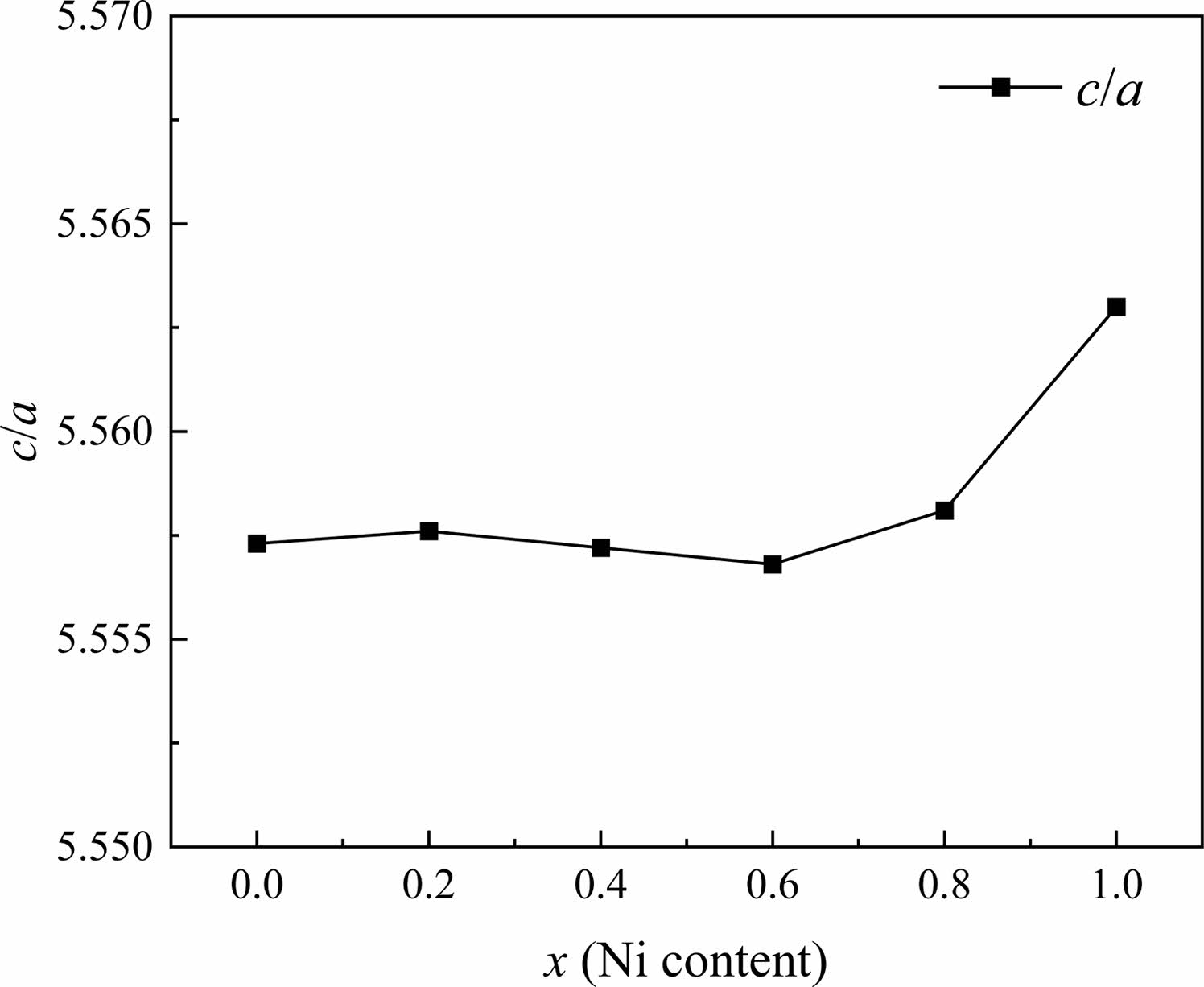
In W-type hexagonal ferrite, the c-axis rotates easily along the direction perpendicular to the hexagonal plane [27]. Thus rotation causes the change of c more quickly compared with a. The c/a ratio parameter is often used to detect structural types. Fig. 3 gives the change of lattice constants a and c in specimens with different x from 0.0 to 1.0. For W-type hexagonal structures, it can be considered that the c/a should be less than 5.585, as reported by Wagner in reference [28]. The ratios of c/a for all the specimens are listed in Table 1. In this study, the ratio of c/a was between 5.5568 and 5.5630, which remains stable with x.
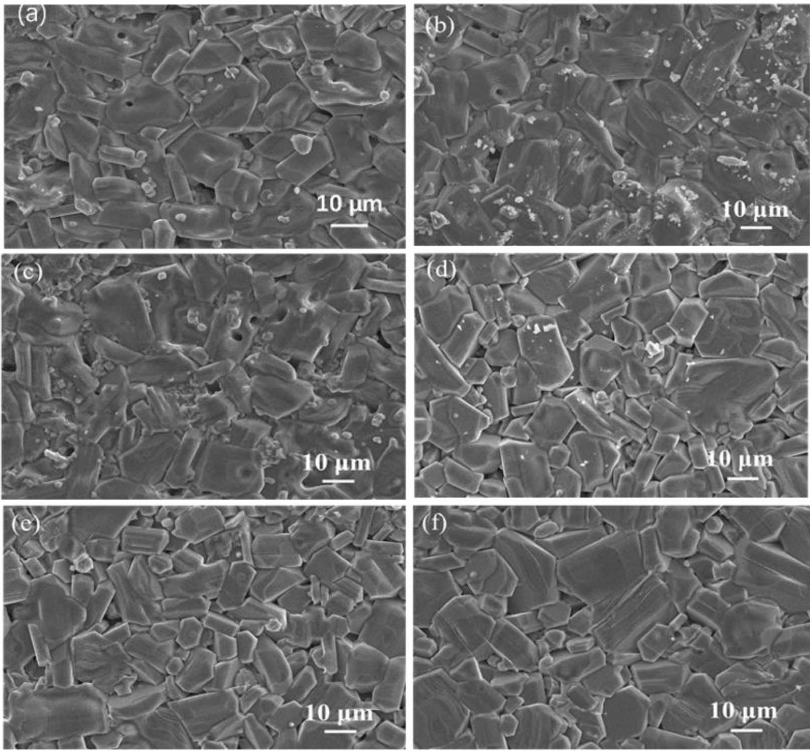
Fig. 4 gives the typical FE-SEM images of specimens with different x. Sometypical hexagonal grains can be observed in the images, and the particle morphology is clear. The comparison between the replaced specimens and the unsubstituted specimens showed that different x had no significant effect on the morphology of the grains.
Magnetic properties
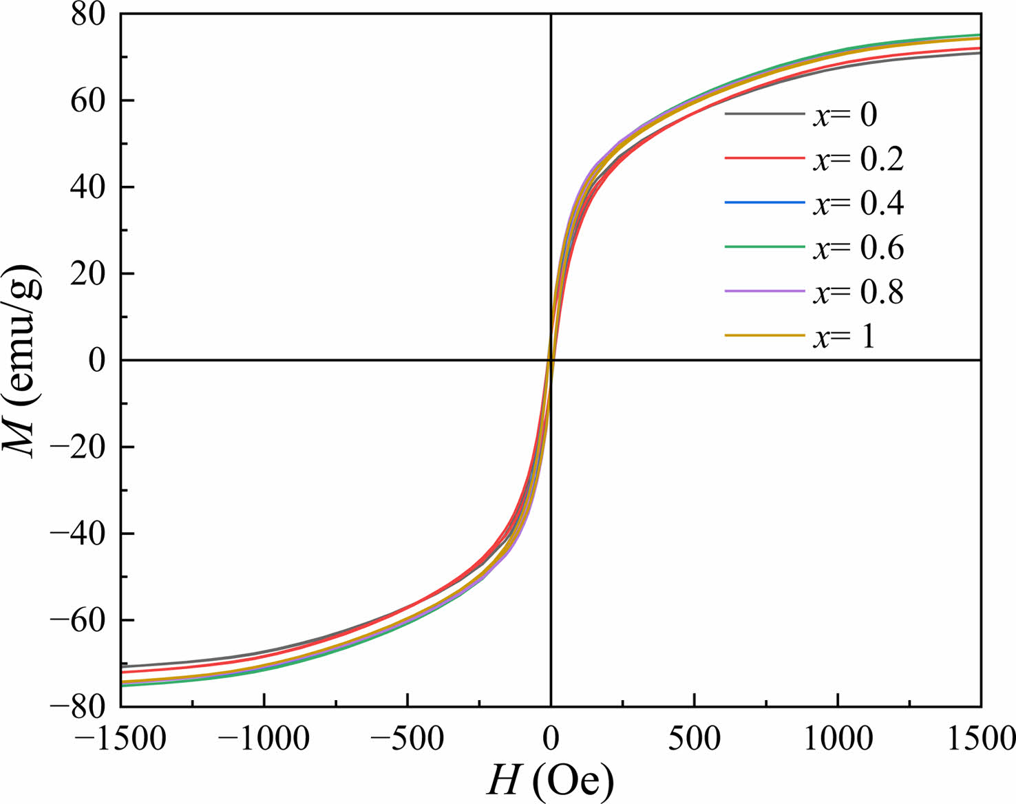
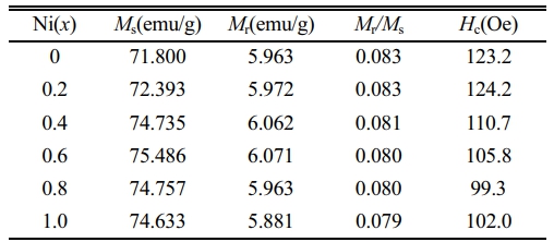
Fig. 5 shows the RT magnetic hysteresis loops of Sr0.9Ce0.1Zn2-xNixFe16O27 specimens. The corresponding magnetic properties of specimens with different x, including the saturation magnetization (Ms), the remanent magnetization (Mr), the coercivity (Hc) and the square ratio (Mr/Ms), were listed in Table 2. It should be pointed out that in Fig. 5, the values of M at the magnetic field of 20 kOe were reckoned as the Ms.
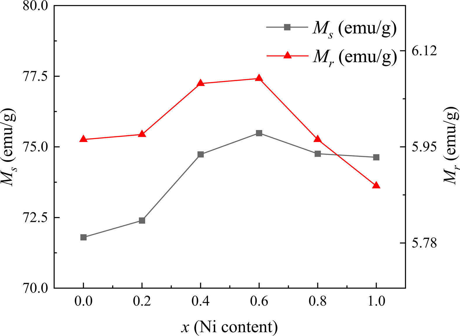
In this study, as can be observed from Table 2 and Fig. 6, the Ms and Mr of specimens first increase from 71.800 and 5.963 emu/g (x=0.0) to 75.486 and 6.071 emu/g (x=0.6), respectively, while both gradually decrease for x≥0.6. The Hc of specimens exhibits the same tendency as Ms and Mr. The trends of Ms, Mr and Hc are consistent with the previous studies [29-32].
In Zn2W hexagonal ferrite, it has been reported that the magnetic moment of Zn2+ ions is 0.0 µB, Zn2+ and Ni2+ ions preferentially occupy the tetrahedral (4e and 4fIV) and the octahedral (4fVI and 6g) sites [24, 26, 33], respectively. Moreover, Ni2+ has a higher octahedral position preference energy than Fe3+. Therefore, Fe3+ cations prefer to occupy tetrahedral positions [5]. When Ni2+ ions replace Zn2+ ions in the W-type structure, the superexchange position between the tetrahedral and octahedral positions is strengthened, increasing the total magnetic moment. Therefore, the Ms of Ni-substituted W-type hexaferrites increases gradually. Meanwhile, as the content of Zn ions decreases, the nonmagnetic of Zn2+ ions occupying the octahedral sites replace the tetrahedral ones and transfer to the octahedral sites in the S blocks. Fe3+ ions migrate from the octahedral to the tetrahedral sites in S blocks, thus affecting the position of Fe3+ ions in the lattice and causing a certain tilt in the magnetic moment direction of Fe3+ ions [5]. In addition, since the magnetic moment of Ni2+ ions (2.0 µB) is smaller than that of Fe3+ions (5.0 µB) [5], the superexchange will be weakened when the substitution of Ni2+ ions reaches a certain extent, which consequently reduces the Ms. This well explains the decreasing Ms and Mr for the specimens with x ≥ 0.6.
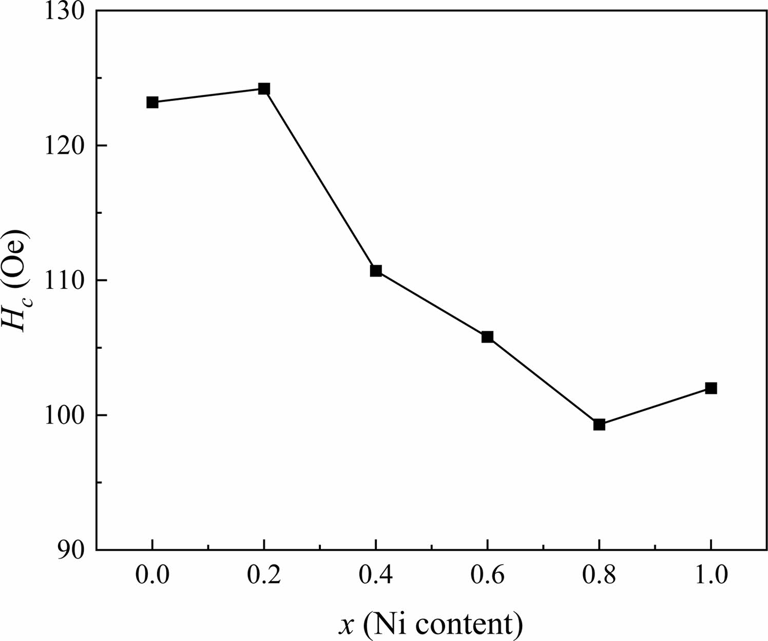
From Fig. 7 and Table 2, it can be observed that the Hc decreases for x between 0.2 and 0.8. Generally, the grain size dominates the value of Hc for magnetic materials. Previous investigation [34] has reported that the changes of grain size can enhance or reduce Hc. Usually, the Hc is inversely proportional to the increasing grain size higher than the critical size of the single domain (Dc) in the sintered specimens [35]. However, it is also affected by the crystallite shape, stress, lattice defects and so on. Therefore, in this study, it can be seen from the figure that the Hc changes irregularly with the increasing x. Overall, compared with specimens without Ni (x=0.0), the Hc of specimens with x>0.0shows a downward trend.
|
Fig. 1 XRD patterns of obtained W-type Sr0.9Ce0.1Zn2-xNixFe16O27 ferrites. |
|
Fig. 2 The change of lattice constants a and c of specimens with different x from 0.0 to 1.0. |
|
Fig. 3 The change c/a of specimens with different x from 0.0 to 1.0. |
|
Fig. 4 Typical FE-SEM images of Sr0.9Ce0.1Zn2-xNixFe16O27 specimens with different x. (a-f): x is from 0.0 to 1.0 with steps of 0.2, respectively. |
|
Fig. 5 RT magnetic hysteresis loops of Sr0.9Ce0.1Zn2-xNixFe16O27 specimens with different x. |
|
Fig. 6 Saturation magnetization (Ms), remanent magnetization (Mr) of specimens with different nickel content (x) from 0 to 1.0. |
|
Fig. 7 The Hc of specimens with different x from 0.0 to 1.0. |
Nickel substituted W-type strontium ferrites with the nominal composition of Sr0.9Ce0.1Zn2-xNixFe16O27 (x is from 0.0 to 1.0 with the steps of 0.2.) were obtained by the traditional ceramic method. It was found that a pure W-phase hexagonal crystal structure without any other impurity was obtained for all the specimens. With the increasing x, the lattice parameters a and c decreased obviously, while the c/a ratio changed slightly. The Ms and Mr of specimens increased for x from 0 to 0.6 and then decrease for x higher than 0.6. However, the Hc changes irregularly with the increasing x due to the different dominating mechanisms.
- 1. N.A. Majid and A.K. Muhammad, Ceram. Int. 44 (2018) 12921-12928.
-

- 2. S. Zhang, C.X. Cao, S.B. Su, A.L. Xia, H.Y. Zhang, H.L. Li, Z.Y. Liu, and C.G. Jin, J. Adv. Ceram. 12.4 (2023) 815-821.
-
- 3. Y.J. Yang, X.S. Liu, and S.J. Feng, J. Ceram. Process. Res. 21[3] (2020) 378-385.
-
- 4. L. Deng, L. Ding, K. Zhou, S. Huang, Z. Hu, and B. Yang, J. Magn. Mater. 323[14] (2011) 1895-1898.
-
- 5. Y.J. Yang, C.L. Chen, and D.Y. Chen, Magnetochemistry 8 (2022) 75.
-
- 6. T.T. Li, Y. Li, R.N. Wu, H. Zhou, X.C. Fang, S.B. Su, A.L. Xia, C.G. Jin, and X.G. Liu, J. Magn. Magn. Mater. 393 (2015) 325-330.
-
- 7. V.I. Itin, A.I. Kirdyashkin, and R.V. Minin, Russ. Non-Ferr. Met. 47 (2006) 20-24.
- 8. G.R. Gordani, M. Mohseni, A. Ghasemi, and S.R. Hosseini, Mater. Res. Bull. 76 (2016) 187-194.
-
- 9. J. Tang, D. Li, H. He, Y. Li, J. Zeng, and C. Liu, Appl. Phys. A. 126 (2020) 277.
-
- 10. P. Gornert, E. Sinn, and W. Schuppel, IEEE Trans. Electromagn. C. 26 (1990) 12-24.
-
- 11. M.J. Iqbal, R.A. Khan, S. Takeda, S. Mizukami, and T. Miyazaki, J. Alloys Compd. 509 (2011) 7618-7624.
-
- 12. Z. Su, Y. Chen, B. Hu, A.S. Sokolov, S. Bennett, L. Burns, X. Xing, and V.G. Harris, J. Appl. Phys. 113 (2013) B305.
-
- 13. T. Akhter, H.M. Khan, S. Honey, and S.S. Hussain, Ceram. Int. 48 (2022) 33177-33184.
-
- 14. X.F. Niu, X.S. Liu, S.J. Feng, and L.V. Farui, J. Ceram. Soc. Jpn. 123 (2015) 920-923.
-
- 15. A.L. Ghasemi, Ceram. Int. 42 (2016) 4143-4149.
-
- 16. X. Niu, X. Liu, S. Feng, F. Lv, F. Huang, X. Huang, Y. Ma, and K. Huang, J. Optik. 126 (2015) 5513-5516.
-
- 17. M.N. Akhtar, K. Ali, A. Umer, T. Ahmad, and M.A. Khan, Mater. Res. Bull. 101 (2018) 48-55.
-
- 18. M.J. Iqbal and R.A. Khan, J. Alloys Compd. 478 (2009) 847-852.
-
- 19. M.J. Iqbal and S. Farooq, J. Alloys Compd. 505 (2010) 560-567.
-
- 20. Y.F. Wu, Y. Huang, and L. Niu, J. Magn. Magn. Mater. 324 (2012) 616-621.
-
- 21. J.J. Xu, H.F. Zou, and H.Y. Li, J. Alloys. Compd. 490 (2010) 552-556.
-
- 22. I. Khan, M.N. Ashiq, I. Sadiq, A.M. Qureshi, and M.U. Rana, J. Chem. Soc. Pak. 34 (2012) 579-583.
- 23. M.J. Iqbal, R.A. Khan, S. Mizukami, and T. Miyazaki, Ceram. Int. 38 (2012) 4097-4103.
-
- 24. K.Y. Jin and K.S. Soo, IEEE Trans. Magn. 38 (2002) 3108-3110.
-
- 25. F. Leccabue, R. Panizzieri, G. Albanese, G. Leo, and N.S. Almodovar, Mater. Res. Bull. 23 (1988) 263-275.
-
- 26. A. Goldman, Modern ferrite technology, Springer, 2006.
-
- 27. F.K. Lotgering, P.H.G.M. Vromans, and M.A.H. Huyberts, J. Appl. Phys. 51 (1980) 5913-5918.
-
- 28. T.R. Wagner, J. Solid State Chem. 136 (1980) 120-124.
- 29. J. Tang, X.S. Liu, D. Li, and Y.J. Yang, J. Mater. Sci.: Mater. Electron. 30 (2019) 284-291.
-
- 30. F.R. Lv, X.S. Liu, and S.J. Feng, Mater. Lett. 157 (2015) 277-280.
-
- 31. G. Albanese, M. Carbucicchio, and G. Asti, J. Appl. Phys. 11 (1976) 81-88.
-
- 32. S. Ram and J.C. Joubert, J. Magn. Magn. Mater. 99 (1991) 133-144.
-
- 33. E.P. Wohlfarth, North-Holland Publishing Company: Amsterdam, The Netherlands 3 (1982) 395-396.
- 34. I. Khan, I. Sadiq, M.N. Ashiq et al., J. Alloys Compd. 509.31 (2011) 8042-8046.
-
- 35. D.Y. Li, F. Wang, A.L. Xia, L.J. Zhang, T.T. Li, C.G. Jin, and X.G. Liu, J. Magn. Magn. Mater. 417 (2016) 355-358.
-
 This Article
-
2023; 24(5): 894-898
Published on Oct 31, 2023
- 10.36410/jcpr.2023.24.5.894
- Received on Aug 15, 2023
- Revised on Oct 10, 2023
- Accepted on Oct 15, 2023
Services
Shared
Correspondence to
- Ailin Xia
-
School of Materials Science and Engineering, Anhui University of Technology, Maanshan 243002, China
Tel : +86-0555-2322181 Fax: +86-0555-2311570 - E-mail: alxia@126.com
Clean-Energy Research Institute(CRI), Hanyang University, 222, Wangsimni-ro, Seongdong-gu, Seoul, 04763, Korea
E-mail: jcpr@hanyang.ac.kr