


- Efficient and eco-friendly plasma preparation and reaction mechanism of low surface-energetic core-shell CaTiO3
Xiaolei Zheng, Qun Wang*, Xiaoqiang Li, Changkuan Zheng and Chenjie Shen
Faculty of Materials and Manufacturing, Beijing University of Technology, Beijing, 100124, PR China
This article is an open access article distributed under the terms of the Creative Commons Attribution Non-Commercial License (http://creativecommons.org/licenses/by-nc/4.0) which permits unrestricted non-commercial use, distribution, and reproduction in any medium, provided the original work is properly cited.
Surface modification of powder materials has always been a key issue that must be faced to improve their application properties and application value. Herein, an efficient and eco-friendly CH4/CF4 plasma method is used for surface modification of materials. The surface modification mechanism of fluorocarbon plasma under different gas flow ratios was detailed investigated by combining the kinetic analysis. The findings demonstrate that fluorocarbon plasma exhibits different modification mechanisms under different modification conditions. The physicochemical properties of the material surface can be easily controlled by adjusting the ratio of fluorocarbon plasma. Functional CaTiO3 particles with core-shell structure were successfully prepared when the gas flow rate ratio R=3. The modified surface exhibited extreme hydrophobicity and the lowest surface energy. This strong application of fluorocarbon plasma technology in material surface modification offers a new avenue to prepare environmentally friendly and functional powders
Keywords: Microwave discharge plasma, Surface fluorination, CaTiO3 particles, Reaction kinetics
Polymeric composites are used in various applications as they are lightweight, flexible, chemically stable, easy to manufacture, low cost, and it is possible to tailor their physical properties, like electrical [1-3], optical [4, 5], thermal [6-8], mechanical [9-11] and frictional [12, 13] properties for various requirements. The powder materials (i.e. fillers), as the functional phase, are the key to determining the properties of the composite material, while the performance is directly tied to the surface characteristics of the filler itself. It is well known that the surface effect is an important characteristic of the filler itself, especially the micro and nano fillers [14, 15]. That is, as the size of the powder particles decreases, the ratio of atoms number on the surface of the powder particles increases dramatically. The surface energy (i.e. surface tension) also increases and leads to the instability of the powder, which is easy to combine with the surrounding particles to form an aggregate and stabilize. Therefore, direct or excessive filling of the polymer will cause serious packing agglomeration. Moreover, the large difference in surface properties between the polymer and the filler results in poor compatibility, making the dispersion of the filler even less favorable [16] As a result, it is difficult to improve material properties, limiting the application of organic/inorganic composites. Surface modification has been proven to be a simple and effective means of improving the physicochemical properties of the filler surface to meet the development of a new composite.
Numerous researchers have carried out a large number of filler surface modification studies on the performance requirements of the target materials. For example, Li et al. [17] achieved improved interfacial compatibility between glass fibee (GF) and polytetrafluoroethylene (PTFE) by coating an organic-inorganic hybrid film on the surface of GF via the sol-gel method. The resulting dielectric composites exhibit a higher dielectric constant and lower dielectric loss. Abiodun et al.18 successfully functionalized Boron Nitride Nanobarbs (BNNB) with glycine through covalent chemisorption to improve the interaction between BNNB and PTFE. Experimental results demonstrate that the modified dielectric composites have significantly enhanced heat conductivity while maintaining outstanding dielectric characteristics. Ren et al. [19] demonstrated the effectiveness of C14H19F13O3Si (F8261) coupling agent modified Al2Mo3O12, which has a fluorocarbon molecular structure similar to PTFE and facilitates the bridging of the filler with PTFE, thereby improving the dielectric properties of the composite. Obviously, surface modification can be considered as a significant "soft technology" for boosting the powder's "hard power". However, the surface treatment technology widely used at present is mostly chemical methods, its disadvantages such as powder modification in small quantities, expensive cost, complex operation, harsh reaction conditions, long time, and environmental pollution are also obvious. Therefore, it is significant to seek an efficient and universal surface modification strategy to improve the application value and application performance of powders.
The low-temperature plasma surface modification methods show the incomparable advantages and great potential of traditional methods [20, 21], which can easily cross the high barrier of conventional chemical reaction with a series of physicochemical effects on the material surface through the high-energy, high-activity substances generated by gas ionization, and achieve the functionalization of the material surface under mild conditions [22, 23]. Moreover, the plasma treatment method has a short action time, and high efficiency, occurs only in the surface layer allowing maximum retention of the bulk properties, and is in a dry state, pollution-free, and easy to operate [24]. Therefore, plasma treatment is expected to be an effective means of introducing reactive groups on the material surface or coating it with a plasma polymer film to improve its physicochemical properties. However, most of the current studies are based on low-temperature plasma technology for polymer surface treatment, and few involve the surface characteristics modification of micro and nano inorganic particles [25, 26]. Exploring the plasma surface modification mechanism of inorganic particles is thus important for achieving adjustable control of particle surface chemical structure and expanding surface modification techniques of other materials.
In this paper, the general rule of plasma surface fluorination modification was investigated using CH4/CF4 as the reaction gas and glass slide as the substrate. The impacts of fluorocarbon plasma modification conditions on the surface chemical structure, surface characteristics, and morphology of materials are thoroughly investigated, and the modification mechanism is elucidated in detail with kinetic analysis. Finally, functional CaTiO3 particles with core-shell structures were efficiently prepared by using the optimal plasma fluorination scheme. Successful use of plasma surface fluoride modification technology to modify the surface properties of fillers opens up new avenues for study into surface modification of ceramic powders and other materials.
Sample preparation
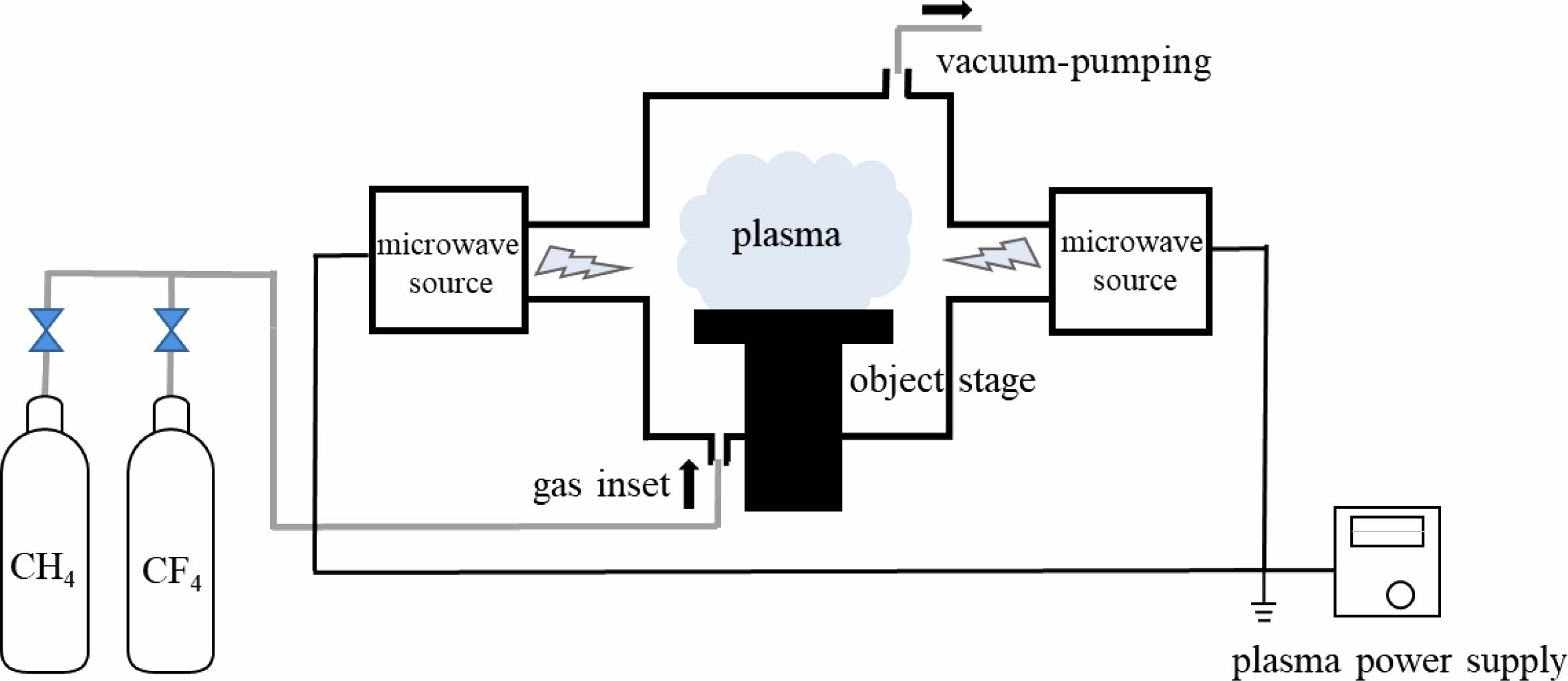
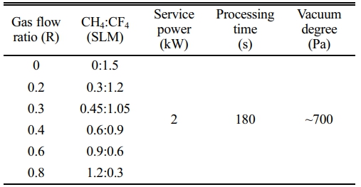
The in-house built microwave plasma reaction device is adopted in this experiment, which primarily consists of a microwave source, microwave transmission system, reaction chamber, vacuum system, gas circuit system and so on, as shown in Fig. 1. The microwave source is a magnetron with an output frequency of 2.45 GHz and a maximum power of 4 kW. The CaTiO3 particles (diameter of 4 μm, provided by Shanghai Dianyang Industrial Co., Ltd) are placed in the middle of the quartz reaction chamber. CH4 and CF4 as reaction gases are passed into the reactor and the flow rates are controlled by their respective flowmeters. The total gas flow rate is fixed at 1.5 SLM and change the reaction gas flow ratio (R). The treatment time is 180 s with a power of 2 kW. Table 1 shows the gas flow rates and the plasma modification parameters.
Characterization
The effect of plasma on the crystal structure of the samples was analyzed by x-ray diffraction (XRD, D8 Advance) with scanning 2θ angles from 20° to 90°. X-ray photoelectron spectroscopy (XPS, Escalab 250Xi) and Fourier transform infrared spectroscopy (FTIR, Spectrum II) were employed to analyze the elemental composition and chemical structure of sample surfaces, respectively. Scanning electron microscope (SEM, Quattro S) was used to observe the surface morphology of the samples, which were sprayed with gold prior to observation. The surface properties of the sample are revealed by a Contact Angle measuring instrument (Date Physics OCA35).
|
Fig. 1 Schematic illustration of plasma modification platform. |
Plasma fluorination deposition conditions and mechanism
Surface structural characterization
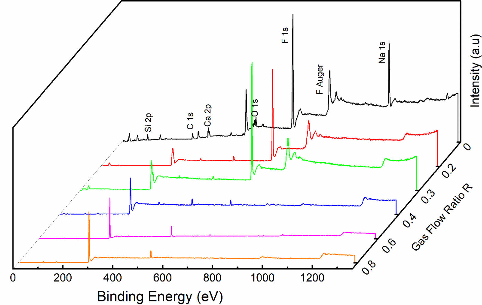
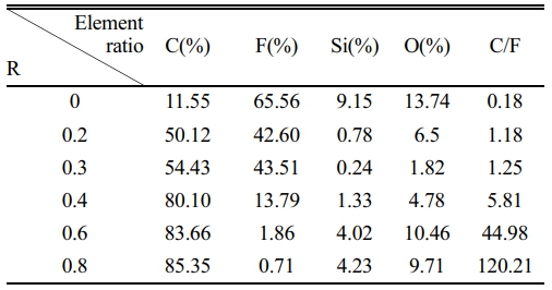
To achieve the preparation of functional core-shell structure CaTiO3 particles, the general rules of plasma surface fluorination modification were first investigated. The commercially available glass slide was selected as the research substrate. Fig. 2 displays the XPS spectra of the modified glass slide with various R. The relative element contents on its surface are listed in Table 2. Obviously, the presence of F1s peak and FAuger peak at binding energies 688 eV and 833 eV, respectively, indicates the successful introduction of fluorine functional groups on the sample surface during plasma fluorination [27]. Meanwhile, it is worth noting that the C1s peak and F1s peak show different trends as R increases. The C1s peak exhibits consistent increase, whereas the F1s peak demonstrates a fluctuating pattern of decrease, increase, and subsequent decrease. The corresponding content of elements C and F exhibits a similar trend, which led to a gradual increase in the C/F element ratio, as shown in Table 2. This demonstrates that both the surface fluorination mechanism and the composition of the modified layer are subject to change as R in the plasma fluorination process.
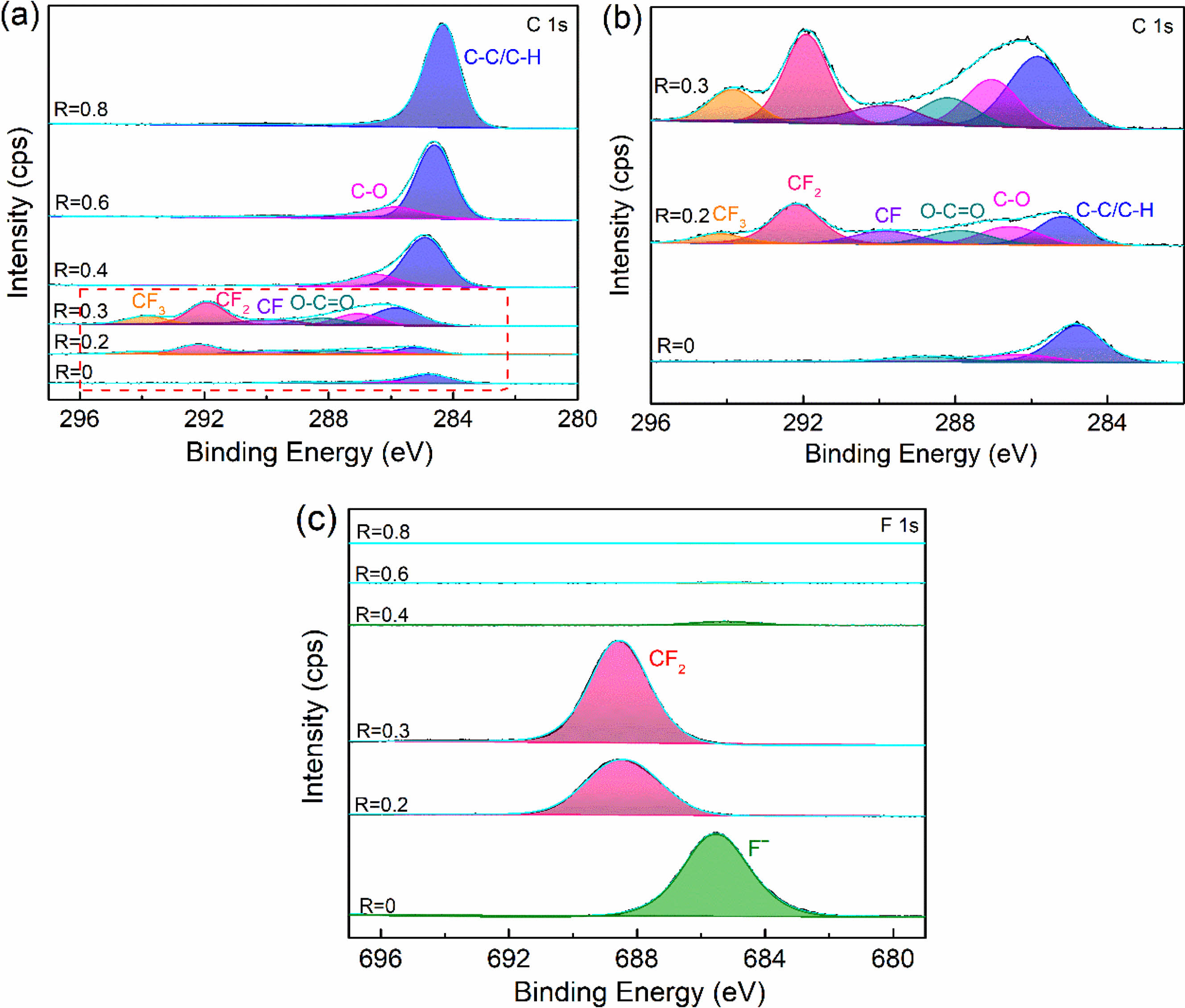
To further verify the chemical bonding on the surface of plasma fluorinated samples, the peak fitting of C1s and F1s of the XPS narrow scan spectrum was carried out. To explore the mechanism of surface fluorination and the transformation of surface modified layer components. From Fig. 3(a), it can be found that with the increase of R, the composition of surface functional groups has changed significantly. Three chemical bonds of C-(C, H), C-O, and O-C=O with binding energies of 284.8 eV, 286.6 eV and 288.5 eV are visible in the C1s signal when R=0. When R is 0.2 and 0.3, the new peaks develop with binding energies of 293.9 eV, 291.8 eV and 289.8 eV, which are related to the chemical bonds CF3, CF2 and CF [28]. The shift of the C-(C, H) peak is due to the fact that fluorine tends to cause larger chemical shifts in other elements, as shown in the enlarged image of Fig. 3(b). As the R increases further, the fluorocarbon group gradually disappears until R=0.8 is transformed into a C-(C, H). Combined with the high-resolution spectra of F1s, it can be seen that only when R=0.2 and 0.3, the peak of F1s appear at 688.4 eV, indicating the chemical valence of CF2. While at other conditions, it can be clearly found from Fig. 3(c) that the peak centered at a binding energy of 685.5 eV coincided well with F-. And with the increase of R, the peak gradually decreases to disappear. According to the above results, it can be known that the various modification conditions demonstrate distinct fluorination mechanisms and generate different modified layers. More fluorine functional groups, primarily organic carbon-fluorine bonds, can be introduced when R=0.3, leading to the formation of an organic fluorocarbon modified layer via plasma polymerization deposition on the sample's surface. However, another modification mechanism exists in the plasma fluorination process. Fluorine is grafted to the sample's surface via injection/sputtering and exists in the form of an ionic bond (Such as R takes 0 or 0.4). The disappearance of fluorine functional groups indicates a gradual transition in the composition of the modified layer from an organic fluorocarbon polymer to an organic hydrocarbon polymer.
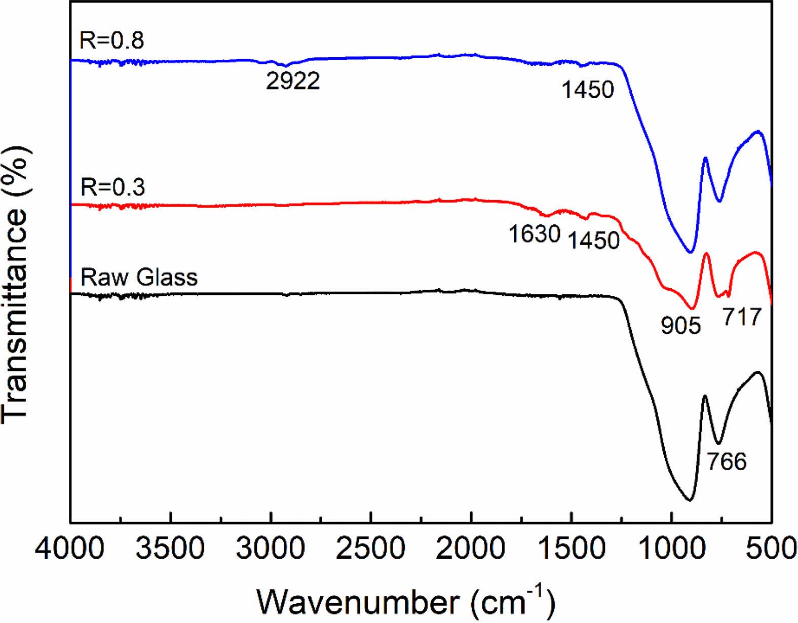
Furthermore, FTIR analysis was also performed to determine the functional groups on the sample surface, as shown in Fig. 4. All samples exhibit significant characteristic peaks at 905 cm-1 and 766 cm-1, which are related to the symmetric and asymmetric stretching vibrations of the Si-O bonds in SiO2 [29]. After plasma modification at R=0.3, the appearance of the bending vibrational peaks of -CF2 and -CH2 proved the formation of organic fluorocarbon film on the sample surface, which corresponded to 717 cm-1 and 1450 cm-1, respectively [30]. While the characteristic peak located at 1630 cm-1 can be attributed to bending vibrations of –OH, which may be caused by the physical absorption of H2O during the tests. When R=0.8, it is obvious that the characteristic peak of fluorine functional groups disappears. On the contrary, an asymmetric stretching vibration peak of -CH2 appeared at 2922 cm-1, indicating that the surface modified layer had changed into an organic hydrocarbon film [31, 32]. FTIR analysis further validates the XPS results.
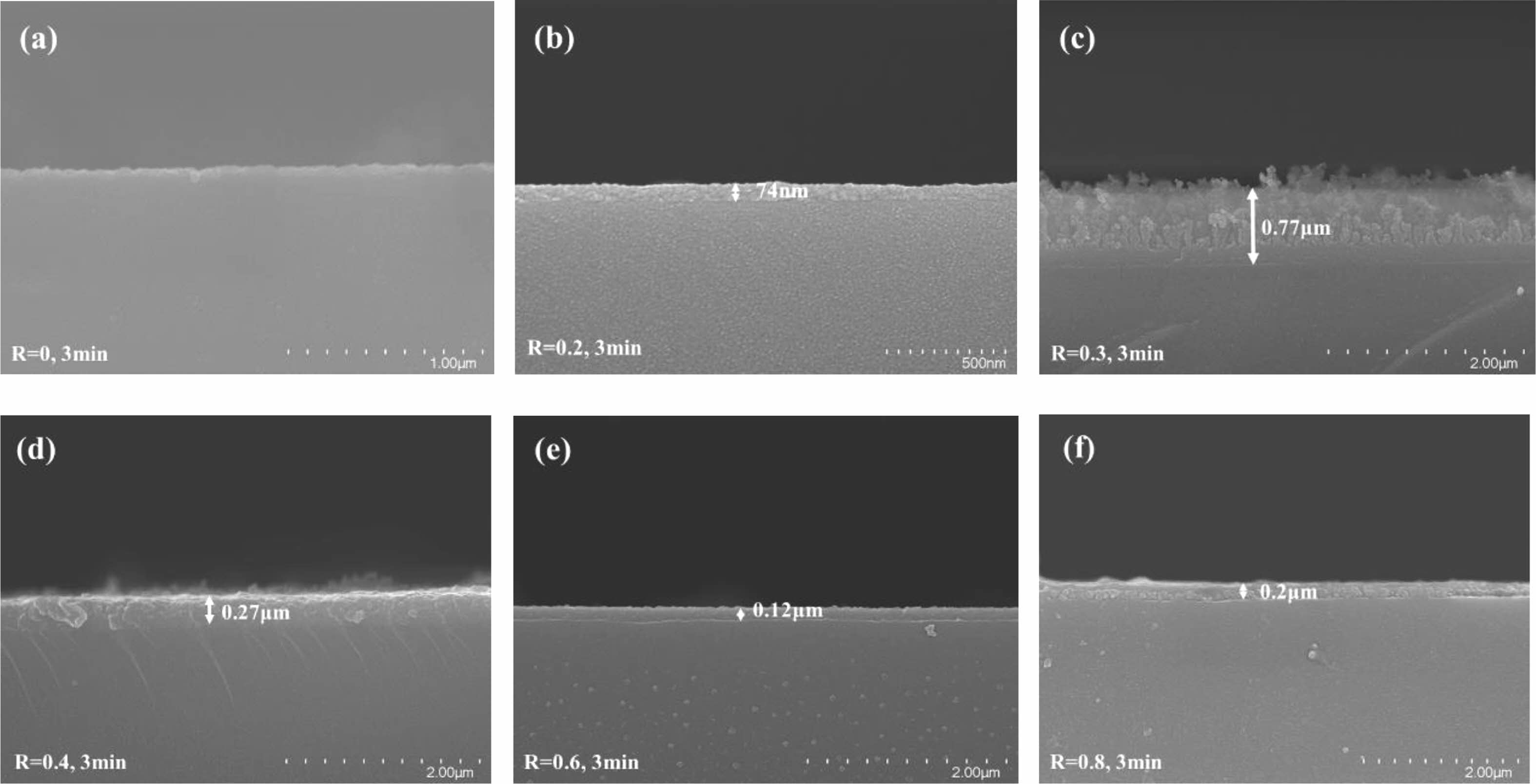
Fig. 5 shows the cross-sectional structure of the series of modified samples. Except for R=0, it is seen that the glass's surface is covered in a polymer coating. This is attributed to the fact that the plasma produced by pure CF4 gas contains not only high-energy particles that bombard the surface of the material causing physical etching but also a high density of chemically etched F-atoms, both of which cause the surface of the material to bumpy and rough, as shown in Fig. 5(a). In contrast, the introduction of CH4 gas produces a polymerizable plasma in which reactive groups interact to form a plasma polymer to generate a cladding layer on the surface of the material. It can be seen that at R=0.3 (see Fig. 5(c)), the thickness of the deposited cladding is the largest, indicating that the polymerization deposition rate is the maximum at this moment, which is most favorable for the creation of organic fluorocarbon polymer films. In addition, it was observed that the surface of the deposited cladding was uneven and pitted, possibly due to the etching that accompanied the polymerization deposition process, suggesting that the plasma polymerization process is accompanied by both polymerization and etching mechanisms of interaction.
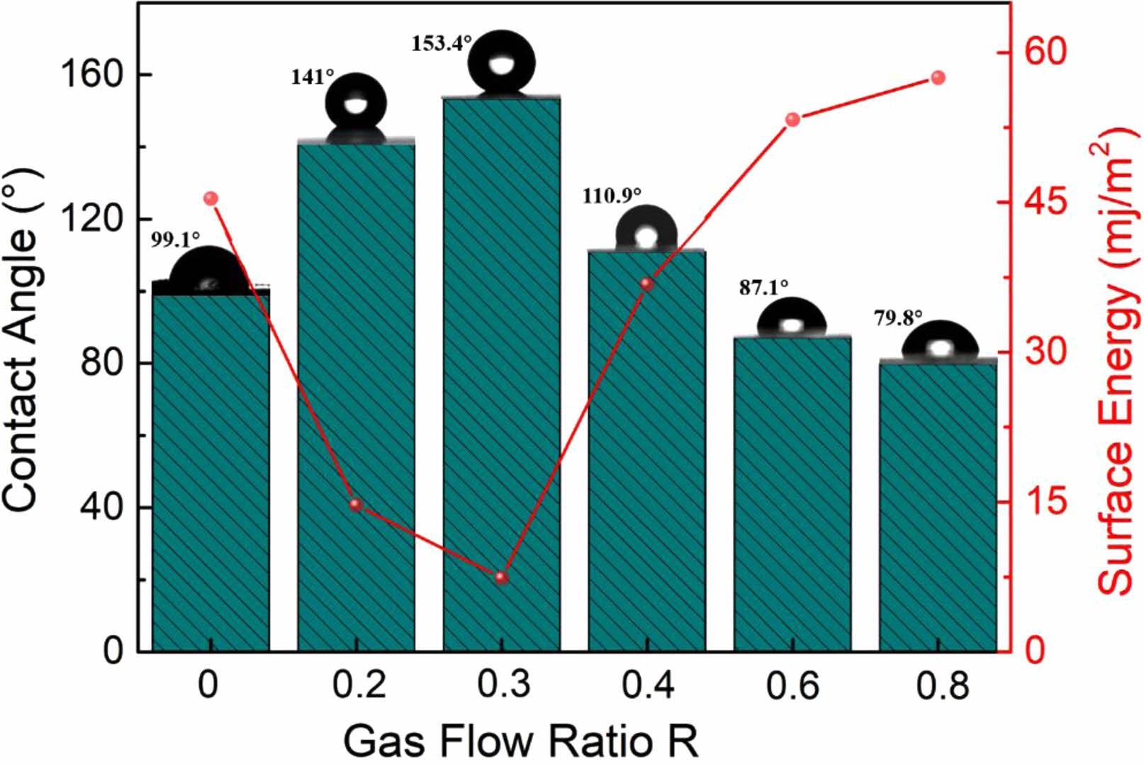
Usually, a material's surface characteristics vary dramatically after being modified. Therefore, the contact angle test is used to assess the hydrophilicity and hydrophobicity of the material surface under various modification conditions. In contrast to the surface energy, which behaves oppositely, the water contact angle is found to rise and then reduce when R rises, as illustrated in Fig. 6. Where, at R=0.3, the fluorinated modified sample has a surface contact angle of 153.4°, exhibiting extreme hydrophobicity and a minimum surface energy of 7.4 mj/m2. According to the analysis above, this is because at R=0.3 the modified material is coated with a fluorocarbon polymer modified layer on the surface, thus exhibiting extreme hydrophobicity and low surface energy.
Surface fluorination mechanism and modification kinetics
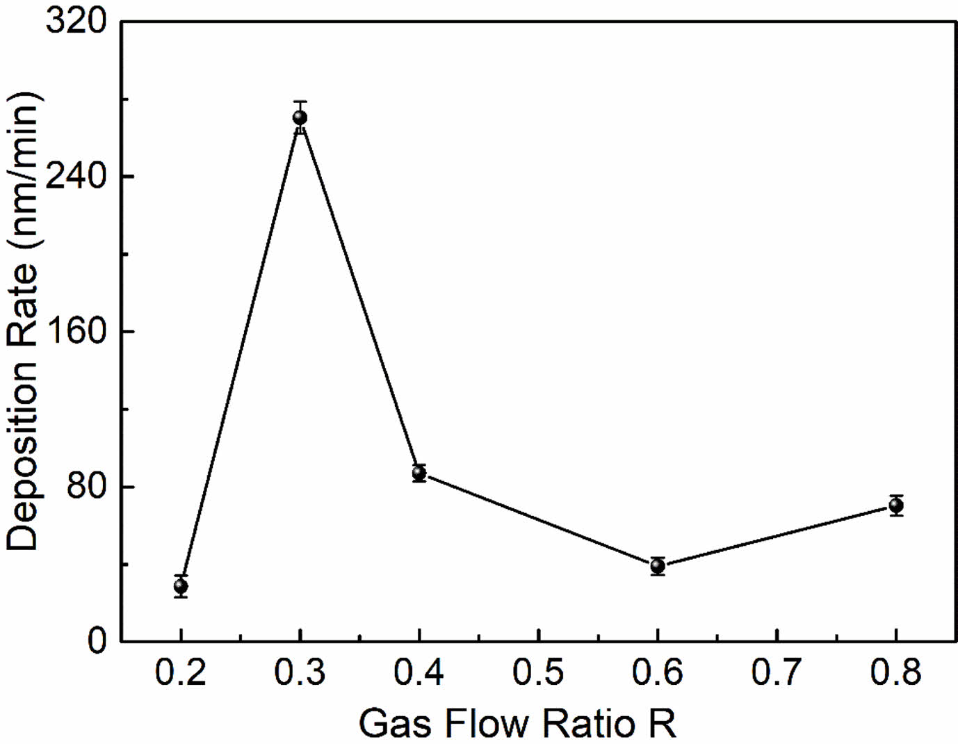
The variation of the modified layer's deposition rate with R is seen in Fig. 7. The deposition rate of the modified layer is intimately dependent on the deposition precursor radicals and their action in the plasma, and the magnitude of the deposition rate is a result of the competition between the two mechanisms of plasma polymerization and etching. As can be seen from Fig. 7, the deposition rate first increases and then decreases with R. When R=0.2 (i.e. high CF4 flow), the fluorocarbon saturated gas is in the microwave discharge environment, the C-F bond breakage occurs due to the collision of high energy particles, causing a larger density of F atoms than the CFn (n=1~3) radical density in the plasma discharge space. The stronger plasma etching effect in this instance overpowers the polymerization effect, which is the main cause of the poor deposition rate. As the increase of CH4 flow (i.e. R increases), the introduced hydrogen source extracts the HF out, which inhibits etching and ensures the production of very high-density film-forming CFn (n=1~3) groups. These groups react with each other to form a fluorocarbon polymer, which enhances polymeric deposition. It is clear that at R=0.3, the deposition rate reaches its maximum. The reaction mechanism can be expressed as follows. First CF4 and CH4 are ionised:

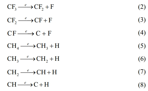
Since the energy of the F-F bond (153 kJ/mol) is less than that of the H-F bond (558 kJ/mol), H atoms combine with the F atoms to form a more stable structure. Therefore, HF extraction occurs:

This leads to a weakening of the etching effect and the dominance of the plasma polymerization effect, at which time the C-F functional groups in the plasma react and polymerize with each other to form a plasma polymer with a specific structure:

As the R continued to increase, the number of CFn groups produced in the plasma began to decrease, on the contrary, the film-forming CHn (n=1~3) groups gradually increased, so the plasma polymerization products gradually changed into hydrocarbon polymer deposition. The deposition rate decreases with increasing R due to the low deposition rate of CH4 itself.
The above reaction process cannot be achieved in pure CF4 gas, as there is no hydrogen source in the pure CF4 gas plasma, with no HF extraction, and the discharge space is filled with a high density of etched F atoms. As a result, the material's surface cannot develop a polymer layer (see Fig. 5(a)). In other words, CF4 is a non-polymeric gas and will therefore produce a different modified surface structure, as described in the XPS analysis, that is, fluorine functional groups are introduced to the material’s surface via grafting, fluorination or injection.
The actual plasma polymerization reaction is considered to be an extremely complex process and to analyze plasma polymerization in more depth, Park et al. initially used a macroscopic kinetic approach to simplify this process and thus speculate on the reaction mechanism. According to this model, the mass deposition rate of the resultant product can be expressed by the quasi-Arrhenius equation as follows: [33]
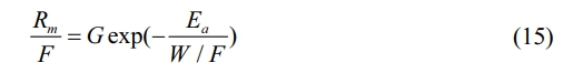
where Rm, W, F, G and Ea denote the mass deposition rate, plasma power, monomer flow rate, geometric factor and apparent activation energy, respectively. This formula indicates that the energy per particle input in the plasma region determines the product generated, that is, the specific energy received per unit molecule (W/F) determines monomer activation (dissociation) in the plasma. From this, the resulting active substances interact and grow into films. It establishes the relationship of mass deposition rate on plasma process parameters and gives a macroscopic description of plasma polymerization, which Hegemann et al. validate [34, 35].
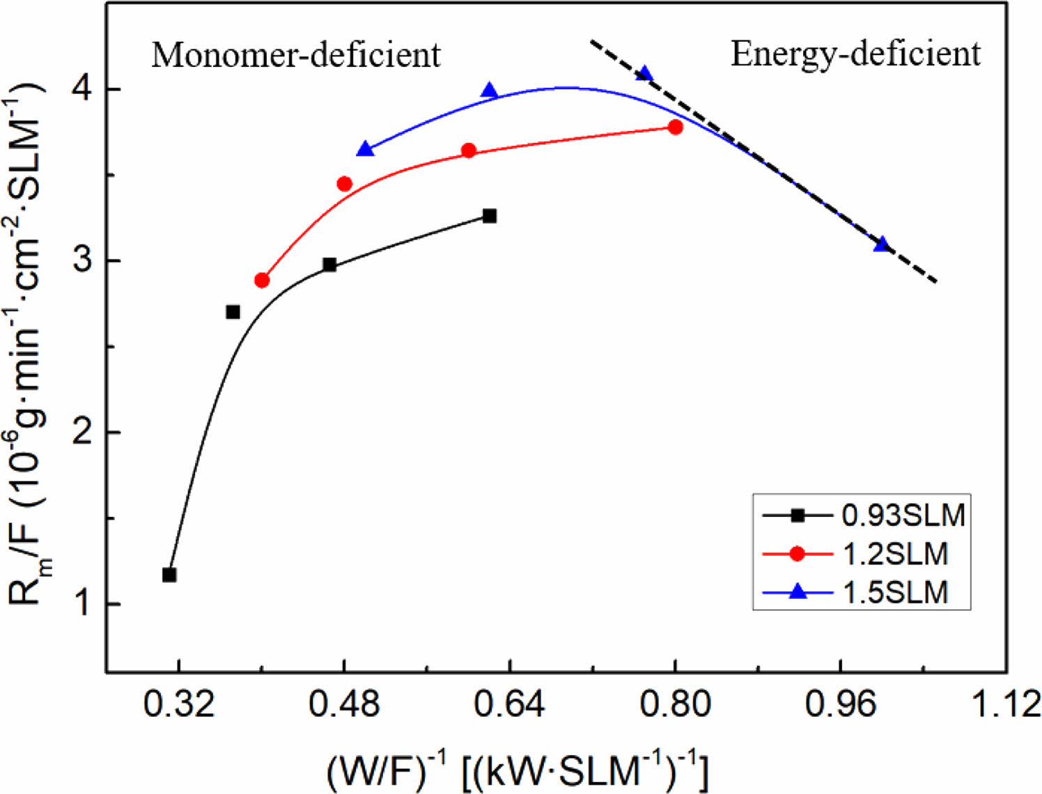
Hence, the optimal conditions for fluorination deposition (R=0.3) were selected, the total gas flow rate was fixed (0.93SLM, 1.2SLM, 1.5SLM) and the input power was varied (1.5 kW, 2 kW, 2.5 kW, 3 kW) to conduct a kinetic investigation to further determine the mechanism and reaction process of the plasma polymerization of the fluorocarbon mixture gas. An Arrhenius plot for the per gas flow fluorocarbon mixture gas is shown in Fig. 8. According to Hegeman et al., the linear relationship between deposition products and specific energy indicates a radical-dominated kinetics, which means that the plasma polymerization process is caused by the interaction of radicals formed in the plasma, resulting in the formation of a polymer deposition product with a randomly cross-linked network structure [36, 37]. In the linear region, sufficient active monomers are present in the plasma to form a monomer enrichment zone. A shift in the deposition film growth mechanism can be found from the deviation of the straight line, namely, at high specific energies there is a significant impact on the kinetics owing to ion-induced effects, resulting in a decrease in the deposition rate. In this region, the low number of active monomers in the plasma forms an energy enriched region zone with enhanced etching and sputtering effects [38].
The linearly fitted slope in the graph is the apparent activation energy Ea, which is related to the plasma chemical processes within the active plasma region and provides information on the reaction mechanism. The value of Ea corresponds to the dissociation energy of the monomeric chemical bonds. Therefore, the radical formation mechanism of each monomer can be hypothesized by measuring the activation energy [39, 40]. It is known that the dissociation energies of each energy level of CF4 are: CF3-F, 5.6 eV/molecule; CF2-F, 2.2 eV/molecule; CF-F, 6.1 eV/molecule; and C-F, 5.2 eV/molecule (corresponding to 6.13 MJ/kg, 2.4 MJ/kg, 10.65 MJ/kg, and 5.67 MJ/kg, respectively). Therefore, it requires approximately 24.85 MJ/kg if assuming that all the bonds are broken. Similarly, the dissociation energy of each energy level of CH4 is: CH3-H, 4.55 eV/molecule; CH2-H, 4.58 eV/molecule; CH-H, 4.58 eV/molecule; C-H, 5.51 eV/molecule (corresponding to 26 MJ/kg, 27.48 MJ/kg, 27.48 MJ/kg and 33.06 MJ/kg, respectively), so approximately 114.02 MJ/kg would be required to break all the bonds. The experiment shows that the activation energy Ea of fluorocarbon mixture gas is 240.72 KJ/L, which is equal to 84.91 MJ/kg by using the ideal gas law. It can be seen that there is enough energy to break the bonds of CF4 to form reactive radicals, from which the mechanism of radical formation in plasma polymerization can be presumed to be the dissociation of CF4 and a portion of CH4, further proving the fluorocarbon mixture gas plasma polymerization reaction described above.
Structual characterization and mechanism of Fluorinated CaTiO3
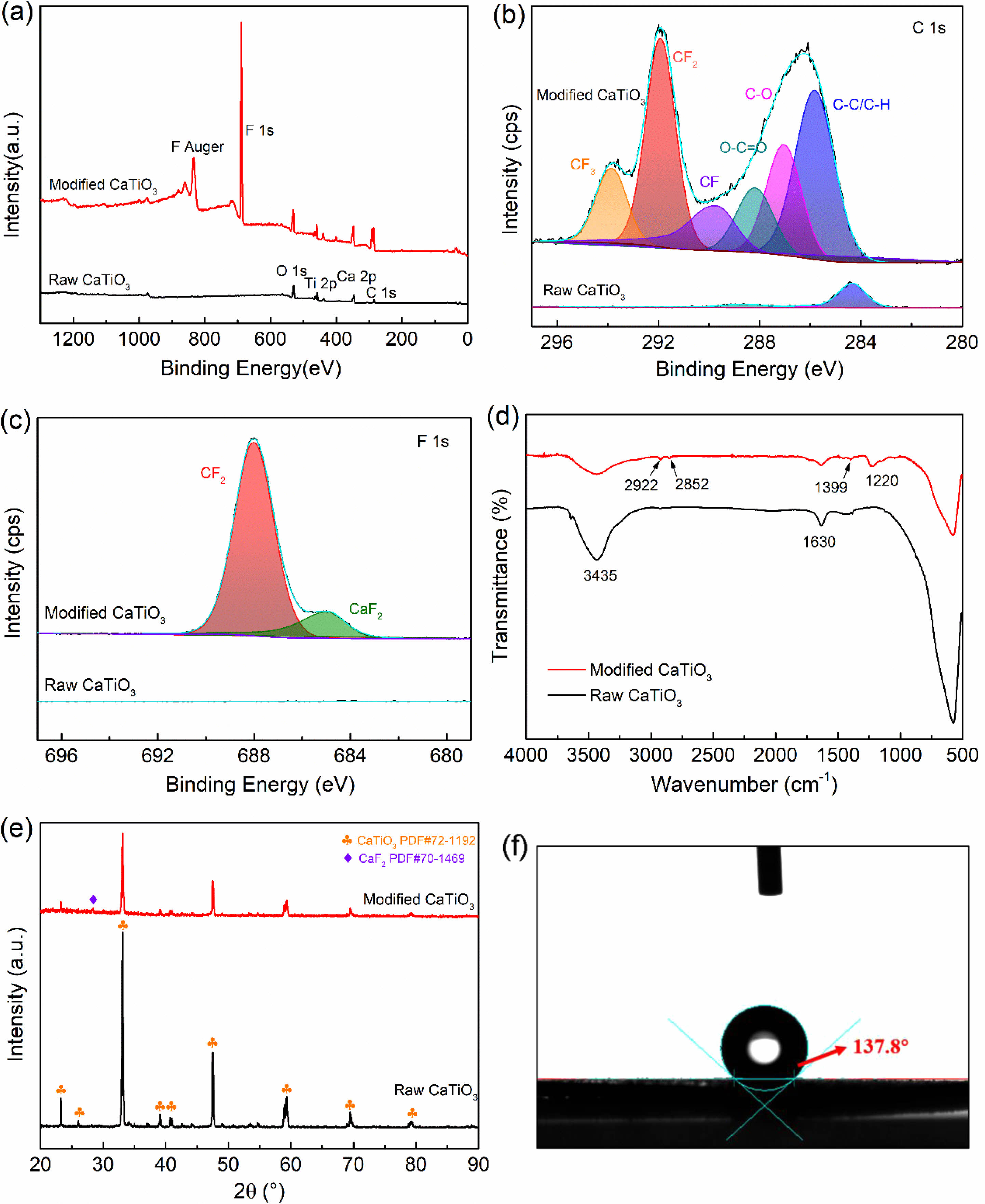
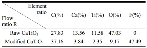
Following the discussion above, the ideal modification conditions (R=0.3, 2 kW) are selected in this section for the preparation of organic polymer-coated low surface energy core-shell CaTiO3 particles. XPS spectral scanning was used to obtain the chemical structure of the CaTiO3 surface as shown in Fig. 9. Experimental results show that fluorine functional groups appear only in the plasma-modified CaTiO3 particles, while the absence of peaks at the same binding energy positions in the raw CaTiO3 particles proves the success of the plasma fluorination modification. Moreover, the relative content of element F on the surface of the modified CaTiO3 is up to 47.49% as illustrated in Table 3. Combined with the high-resolution spectra of C1s and F1s, the peaks detected at the binding energies of 293.3 eV, 291.2 eV and 289.8 eV (Fig. 9(b)) on the modified CaTiO3 surface are assigned to the chemical bonds of CF3, CF2 and CF, respectively [31]. Furthermore, the peak with binding energy at 689 eV (Fig. 9(c)) confirms the presence of CF2. This indicates that an organic fluorocarbon modified layer has formed on the surface of CaTiO3. On the other hand, the binding energy peak at 685.8 eV is attributed to CaF2, which indicates that the plasma treatment was accompanied by a sputtering/injection process where a small amount of fluorine was grafted onto the particle surface in the form of ionic bonds and exists as CaF2. As further confirmation of the formation of the organic fluorocarbon modified layer, the FTIR spectra of modified CaTiO3 detected a new characteristic peak at 1220 cm-1, which can be considered as an asymmetric stretching vibration of -CF2 [41]. While the characteristic peaks at 2922 cm-1 and 2852 cm-1 belong to the asymmetric and symmetrical stretching vibration peaks of -CH2, respectively [31, 32]. In conclusion, an organic fluorocarbon polymer modification layer was successfully coated to the CaTiO3 surface.
XRD was conducted to investigate the influence of plasma fluorination on the phase structure of CaTiO3. A weak peak at 28.3° was seen for plasma fluorinated CaTiO3, corresponding to the (111) plane of CaF2 (PDF#70-1469), as illustrated in Fig. 9(e). This suggests that a small amount of CaF2 was introduced on the CaTiO3 surface owing to the sputtering/injection effect of the plasma, which is consistent with the XPS result. In addition, the modified CaTiO3 retains the same crystalline structure as the original sample, and the plasma modification only acts on the surface, mainly changing the surface morphology of the filler particles, thereby having less impact on the overall structure of the crystalline material. Meanwhile, the water contact angle was explored to highlight the significant change in the surface characteristics of CaTiO3 particles generated by fluorination modification. Where the raw CaTiO3 powder is completely wetted owing to its high surface energy. After fluoridation modification, the contact angle of CaTiO3 increased to 137.8°, reflecting an extremely hydrophobic nature and lower surface energy (16.9 mj/m2). It is well known that the polymer has a low surface energy, so we are convinced that fluorinated filler particles filling the polymer (particularly fluorinated polymers) will be beneficial in reducing the interfacial discrepancy between the two, promoting dispersion and compatibility. In the future, we will investigate this aspect of our work.
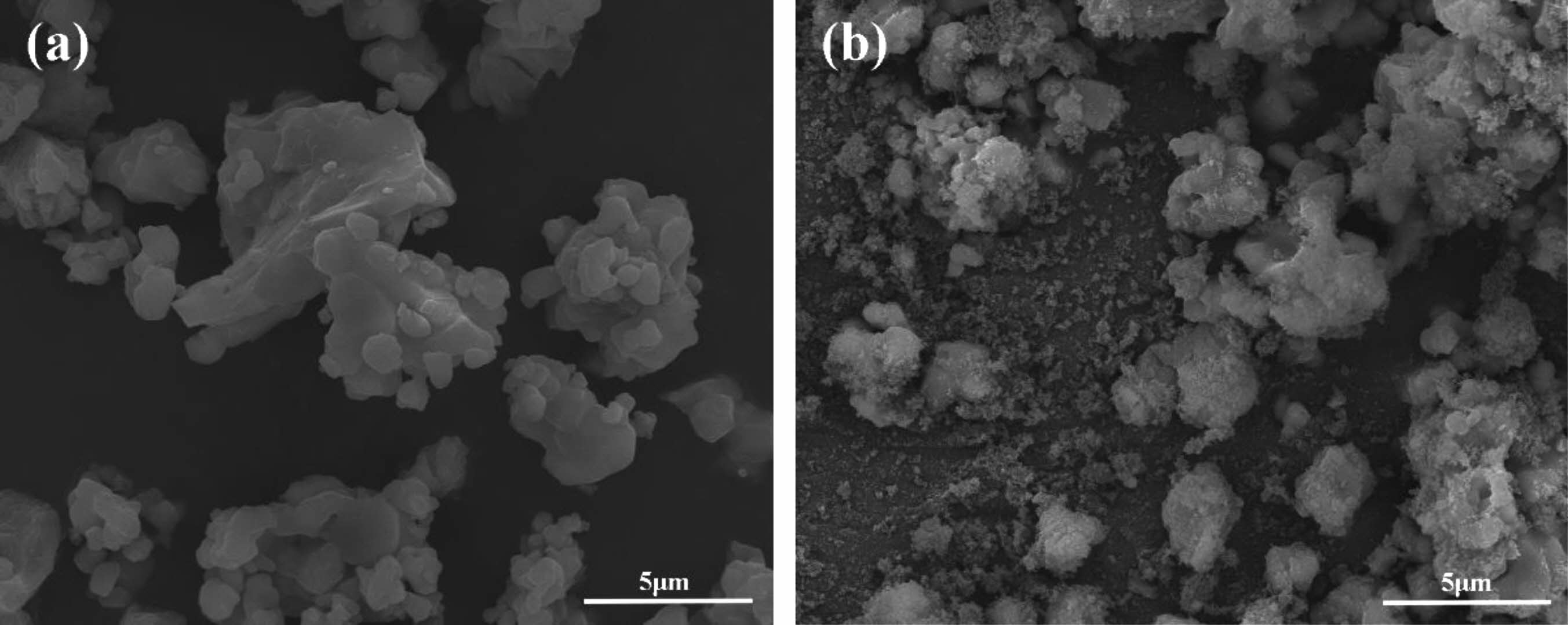
The morphological characteristics of raw CaTiO3 and modified CaTiO3 particles were observed via SEM, as shown in Fig. 10. The SEM images clearly show that the surface micro-morphology of the original and changed samples differs dramatically. The surface of fluorinated modified CaTiO3 particles was covered by tiny organic molecules and thus seems rough, compared to Fig. 10(a). The fact illustrates that the preparation of organic fluorocarbon polymer coated ceramic particles with core-shell structure has been successfully achieved by fluorocarbon mixed gas plasma.
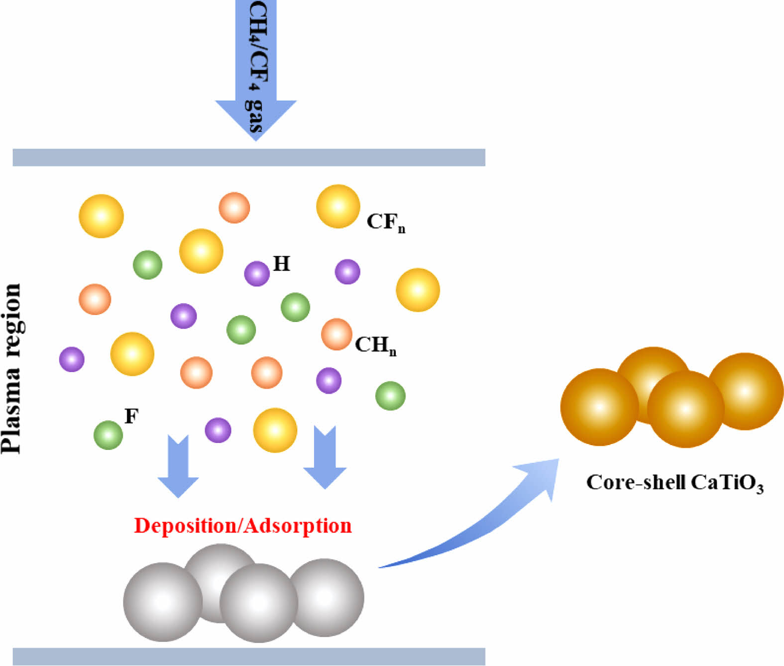
In summary, the mechanism of CaTiO3 plasma surface modification can be described using the schematic shown in Fig. 11. Excitation ionization of gas monomers can yield a huge number of electrons, ions, and neutral species with high energy and activity. They can easily exchange energy, permitting high barrier reactions to be completed in minutes under mild conditions. In the CH4/CF4 gas plasma, the electrons will collide and ionize with CH4 and CF4 molecules, primarily forming a large number of highly active CFn, CHn groups. These active groups collide and contact each other in the plasma space to initiate polymerization and deposition onto the solid surface. Meanwhile, the active groups that have been adsorbed onto the solid surface become active sites, causing plasma polymerization and the generation of macromolecular polymers. Consequently, polymer-coated functional core-shell CaTiO3 particles were successfully obtained.
|
Fig. 2 XPS spectra of fluorinated samples with various R. |
|
Fig. 3 C1s and F1s narrow scan spectra of fluorinated samples. |
|
Fig. 4 FTIR spectra of samples with various modification conditions. |
|
Fig. 5 SEM images of cross section of plasma modified sample |
|
Fig. 6 Surface characteristics of modified sample with various R. |
|
Fig. 7 Variation of deposition rate with R. |
|
Fig. 8 Arrhenius diagram for fluorocarbon gas plasma (R=0.3). |
|
Fig. 9 Chemical characterization of CaTiO3: (a) XPS spectra, (b) XPS narrow scan spectra for C1s and (c) F1s, (d) FTIR spectrum, (e) XRD patterns and (f) Water contact Angle of CaTiO3 before and after fluorination. |
|
Fig. 10 SEM images of (a) unmodified CaTiO3 and (b) R=0.3 fluorinated modified CaTiO3 particles. |
|
Fig. 11 Mechanism diagram of plasma fluorination modification CaTiO3 particles. |
|
Table 3 The relative element contents of the sample before and after modification. |
In conclusion, the utilization of a simple and efficient CH4/CF4 plasma technique to alter the material's surface. The element content, chemical structure, morphology, and surface characteristics of fluorinated samples are characterized by XPS, FTIR, SEM and contact angle, respectively. Experimental results demonstrated that plasma fluorination significantly improved the physicochemical properties of the sample surface. Surface modification mechanism varies with fluorocarbon gas flow ratio, CH4/CF4 mixture gas dominated by plasma polymerization, the surface generates a layer of amorphous, crosslinked and tightly bonded polymer layer with the substrate, the components of the modified layer with the change of gas flow ratio of fluorocarbon polymers and hydrocarbon polymer conversion occurs. On the other hand, pure CF4 gas is dominated by etching, where fluorine functional groups are grafted onto the material surface via sputtering/injection. Functional core-shell CaTiO3 particles with extreme hydrophobicity and the lowest surface energy were successfully prepared by controlling the plasma fluorination condition R=0.3. Furthermore, this plasma treatment is highly adjustable and environmentally friendly, providing the theoretical basis for its application to surface modification of other materials.
This work was financially supported by the National Key Research Program (Grant No 2016YFB1200602-37).
Data Availability Statement
All data, models, and code generated or used during the study appear in the submitted article.
The authors declare that there is no conflict of interest regarding the publication of this article.
- 1. H. Shen, W. Wu, H.B. Hu, Z.G. Rui, J.J. Ye, and C. Zhang, Polym. Compos. 44 (2023) 3522-3534.
-

- 2. X.W. Qiu, Z.W. Lin, Y.A. Zhao, J.M. Zhang, X.L. Hu, and H. Bai, Small. 19 (2023) 2300931.
-
- 3. D. Zhang, W.W. Liu, R. Guo, K.C. Zhou, and H. Luo, Adv. Sci. 5 (2018) 1700512.
-
- 4. A. Atta, M.M. Abdelhamied, A.M. Abdelreheem, and M.R. Berber, Polymers, 13 (2021) 1225.
-
- 5. W. Zhang, X.Z. Ji, M. Al-Hashimi, C.X. Wang, and L. Fang, Chem. Eng. J. 419 (2021) 129553.
-
- 6. B.Y. Wen and X.L. Zheng, Compos. Sci. Technol. 174 (2019) 68-75.
-
- 7. H.Y. Shi, W. Zhou, Z.B. Wen, W.X. Wang, X.L. Zeng, R. Sun, and L.L. Ren, Mater. Horiz. 10 (2023) 928-937.
-
- 8. S.M. Wang and B.Y. Wen, Compos. Sci. Technol. 222 (2022) 109346.
-
- 9. S. Sathiyamurthy, S. Saravanakumar, N. Ananthi, and P. Devi, J. Ceram. Process. Res. 24 (2023) 683-692.
-
- 10. A. Samal, S. Kumar, M. Bhargava, and B.S. Roy, J. Bionic. Eng. 20 (2023) 1737-1746.
-
- 11. A.A. Al-Allaq, J.S. Kashan, M.T. El-Wakad, and A.M. Soliman, J. Ceram. Process. Res. 22 (2021) 446-454.
-
- 12. Y. Hua, F. Li, N. Hu, and S.Y. Fu, Compos. Sci. Technol. 223 (2022) 109446.
-
- 13. Y.H. Wu, C.L. Dong, X.Q. Bai, and C.Q. Yuan, Tribol. Int. 167 (2022) 107383.
-
- 14. M. Lashanizadegan, G. Farzi, and N.E. Nia, J. Ceram. Process. Res. 15 (2014) 316-319.
-
- 15. J.J. Zhang, Y.M. Park, X.Y. Tan, M.K. Bae, D.J. Kim, T.H. Jang, M.S. Kim, A.W. Lee, and T.G. Kim, J. Ceram. Process. Res. 20 (2019) 589-596.
-
- 16. T.S. Sasikala and M.T. Sebastian, Ceram. Int. 42 (2016) 7551-7563.
-
- 17. Q.Y. Li, P.Y. Liu, K. Mahmood, N. Zhang, and Y.C. Che, J. Mater. Sci. : Mater Electron. 32 (2021) 23090-23102.
-
- 18. S. Abiodun, R. Krishnamoorti, and A.K. Bhowmick, ACS Appl. Nano Mater. 6 (2023) 3781-3796.
-
- 19. J.Q. Ren, P. Yang, Z.J. Peng, and X.L. Fu, Ceram. Int. 47 (2021) 20867-20874.
-
- 20. Y.Q. Zhang, R.S. Rawat, and H.J. Fan, Small Methods. 1 (2017) 1700164.
-
- 21. K.B. Kim and M. Kim, J. Ceram. Process. Res. 23 (2022) 535-540.
-
- 22. J. Zheng, R. Yang, L. Xie, J.L. Qu, Y. Liu, and X.G. Li, Adv. Mater. 22 (2010) 1451-1473.
-
- 23. H.F. Liang, F.W. Ming, and H.N. Alshareef, Adv. Energy Mater. 8 (2018) 1801804.
-
- 24. K. Bazaka, M.V. Jacob, R.J. Crawford, and E.P. Ivanova, Acta biomater. 7 (2011) 2015-2028.
-
- 25. J. Peran and S.E. Razic, Text. Res. J. 90 (2020) 1174-1197.
-
- 26. M. Bakhshzadmahmoudi, S. Jamali, and E. Ahmadi, Colloid Polym. Sci. 300 (2022) 103-110.
-
- 27. F.C. Luo, B. Tang, Z.X. Fang, Y. Yuan, H. Li, and S.R. Zhang, Appl. Surf. Sci. 503 (2020) 144088.
-
- 28. B.H. Park, M.H. Lee, S.B. Kim, and Y.M. Jo, Appl. Surf. Sci. 257 (2011) 3709-3716.
-
- 29. P. Lu, W.B. Xia, H. Jiang, and H.F. Zhao, Bull. Chin. Ceram. Soc. 34 (2015) 878-881.
- 30. J. Mihaly, S. Sterkel, H.M. Ortner, L. Kocsis, L. Hajba, E. Furdyga, and J. Mink, Croat. Chem. Acta. 79 (2006) 497-501.
- 31. Z.T. Li, Y. Yuan, M.H. Yao, L. Cao, B. Tang, and S.R. Zhang, Ceram. Int. 45 (2019) 22015-22021.
-
- 32. F.C. Luo, B. Tang, Y. Yuan, Z.X. Fang, and S.R. Zhang, Appl. Surf. Sci. 456 (2018) 637-644.
-
- 33. A. Rutscher and H.E. Wagner, Plasma Sources Sci. Technol. 2 (1993) 279.
-
- 34. D. Hegemann, Thin Solid Films. 515 (2006) 2173-2178.
-
- 35. D. Hegemann, E. Koerner, K. Albrecht, U. Schutz, and S. Guimond, Plasma Processes Polym. 7 (2010) 889-898.
-
- 36. D. Hegemann, Pure Appl. Chem. 80 (2008) 1893-1900.
-
- 37. S. Huang, X. Yu, and Z.Y. Ning, Plasma Sci. Technol. 7 (2005) 2669-2672.
-
- 38. D. Hegemann, M.M. Hossain, E. Koerner, and D.J. Balazs, Plasma Processes Polym. 4 (2007) 229-238.
-
- 39. D. Hegemann and M.M. Hossain, Plasma Processes Polym. 2 (2005) 554-562.
-
- 40. D. Hegemann, E. Koerner, and S. Guimond, Plasma processes Polym. 6 (2009) 246-254.
-
- 41. H.W. Yu, W.R. Han, L. Liu, D.D. Gu, W. Mu, and N. Chen, Materials Peports 24 (2014) 95-98.
 This Article
-
2023; 24(5): 874-883
Published on Oct 31, 2023
- 10.36410/jcpr.2023.24.5.874
- Received on Aug 19, 2023
- Revised on Sep 27, 2023
- Accepted on Sep 29, 2023
Services
- Abstract
introduction
experimental
results and discussion
conclusion
- Acknowledgements
- Conflict of Interest
- References
- Full Text PDF
Shared
Correspondence to
- Qun Wang
-
Faculty of Materials and Manufacturing, Beijing University of Technology, Beijing, 100124, PR China
Tel : 86-10-67392755 - E-mail: wangq@bjut.edu.cn
Clean-Energy Research Institute(CRI), Hanyang University, 222, Wangsimni-ro, Seongdong-gu, Seoul, 04763, Korea
E-mail: jcpr@hanyang.ac.kr