


- Design and development of ceramic glaze flow tester with adjustable tilt angle
Ya-nan Xiu*
China Academy of Art, Hangzhou, China
This article is an open access article distributed under the terms of the Creative Commons Attribution Non-Commercial License (http://creativecommons.org/licenses/by-nc/4.0) which permits unrestricted non-commercial use, distribution, and reproduction in any medium, provided the original work is properly cited.
In this study, a ceramic glaze flow tester with adjustable angles was designed to meet the testing requirements for glaze flow at different inclination angles. The tester consists of an angle-adjustable support frame and a glaze scale plate, featuring a sophisticated structure and convenient operation. Experimental results demonstrate that this tester can visually display the flow characteristics of glazes at various inclination angles, and the obtained data is reliable and comparable. The design of this tester offers a novel technical solution and valuable experimental experience for research on ceramic glaze flow, expanding the methodology in this field. It holds promising potential for wide-ranging applications in ceramic glaze design and development
Keywords: Glaze flow, Angle-adjustable support frame, Tester
The flowability of ceramic glazes is a crucial factor influencing the appearance quality and effects of glaze surfaces [1]. Testing the flowability of glazes provides a means to understand glaze characteristics [2], adjust glaze formulations, improve processes, and enhance glaze surface effects. However, there are limited methods specifically designed for testing high-temperature flowability of ceramic glazes [3-6], and most of them employ fixed-angle testing fixtures. Such fixtures can only display the flowability of glazes at a fixed inclination angle and cannot meet the need to test glaze flowability at different angles. To address this requirement, various methods for determining the flowability of similar materials [7-9], international standards [10, 11], national standards [12], industry standards [13], and the latest research [14] were reviewed. Inspired by several national patents on adjustable-angle fixtures [15-23], a simple and convenient adjustable-angle ceramic glaze high-temperature flow tester was developed. The tester comprises an angle-adjustable support frame and a glaze scale plate. This paper describes and analyzes the design, preparation of samples, testing methods, and experimental results of the tester, aiming to provide a scientific basis and samples for glaze flow-related research in this field.
Angle-Adjustable Support Frame
Structural Design
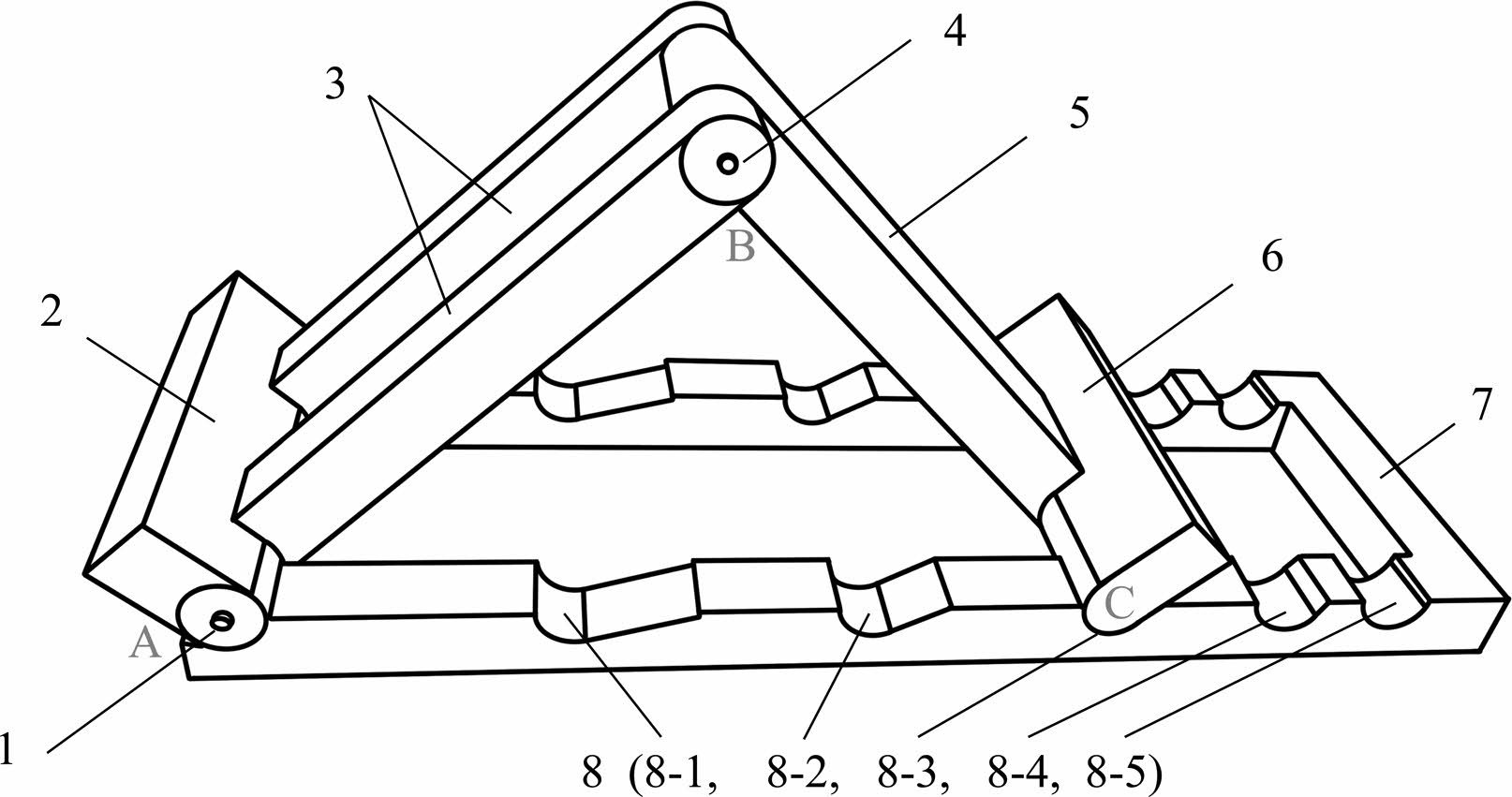
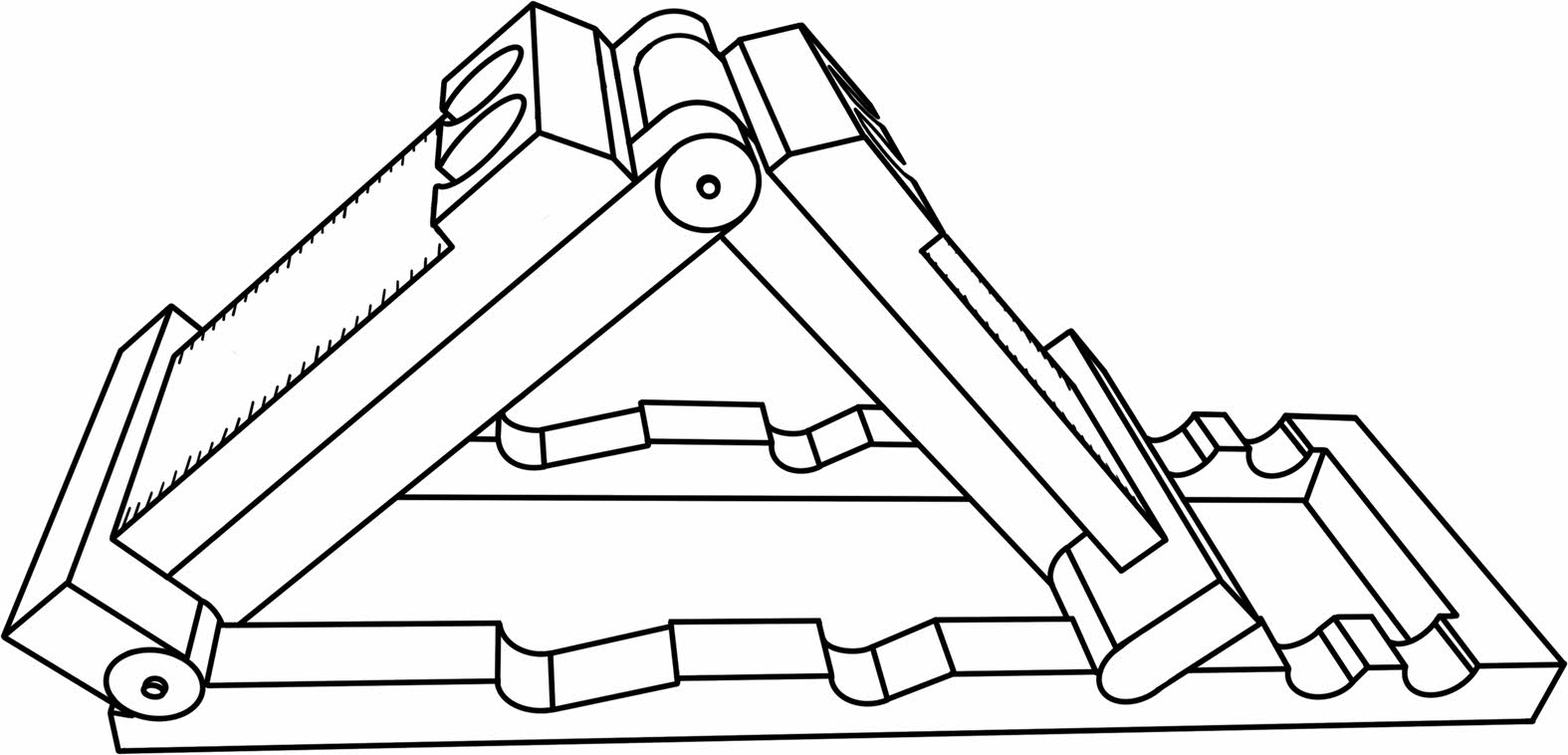
The angle-adjustable support frame is a crucial part to achieve adjustable inclination angles. It needs to meet experimental requirements, including adjustable inclination angles, convenient installation and operation, high stability, low production cost, and high-temperature resistance. After comprehensive analysis and experimentation, the final design of the angle-adjustable support frame was determined as shown in Fig. 1. It mainly consists of a base frame, angle groove, support plate, support rod, connecting bearing, and support rod bearing.
The base frame of the support frame is equipped with an angle groove, and one end of the base frame is equipped with a connecting bearing, which connects to the double support rods. The first support plate is directly connected to one end of the double support rods near the connecting bearing, and the other end of the double support rods is equipped with a support rod bearing. The single support rod is connected to the double support rods through the support rod bearing on one end and directly connected to the second support plate on the other end. The second support plate has a guide groove with a shape that matches the angle groove. The design of double-sided support plates allows for control experiments.
The shape of the angle grooves is meticulously crafted to precise angular measurements within the range of 0° to 90°, with intervals of 15°, resulting in a distinct configuration of five settings (as indicated in Fig. 1). When regarding the base frame, equipped with an interconnected bearing, as the left side, the angle grooves extend seamlessly from left to right, corresponding to the labeled markings 8-1, 8-2, 8-3, 8-4, and 8-5 illustrated in the diagram. These angle grooves are associated with angular measurements of 75°, 60°, 45°, 30°, and 15° respectively.
In the context of precision, the careful design of the angle grooves, each tailored to accommodate varying incline angles, ensures a heightened level of accuracy when adjusting testing angles. Moreover, upon the completion of angle adjustments for the test specimen, the lower edge of the second support plate seamlessly into the angle grooves, forming an isosceles triangular alongside support rods of equal length and the underlying base frame (depicted as DABC in Fig. 1). This particular configuration serves to not only bolster the stability of the test specimen but also guarantee the uniformity and precision of the incline angles on both sides (represented as ∠BAC and ∠BCA in Fig. 1).
Turning to the aspect of efficiency, the meticulously designed angular settings contribute to heightened efficiency in steaming the process of configuring experimental tests. Operators merely need to relocate the support plate to insert it into the corresponding angle grooves to promptly attain the desired angle for experimentation.
Addressing practicality, the dual-sided support plate design of the tester facilitates comparative experiments. In situations where the need arises to conduct multiple parallel tests, it becomes feasible to arrange several sets of test specimens. The uniform design of the tester ensures consistent test conditions, thereby upholding the uniformity and precision of the testing angles. This augmentation serves to significantly enhance the dependability and efficacy of the resulting test outcomes.
Material Selection
Since the angle-adjustable support frame needs to be used inside a kiln, the material used for its construction must withstand temperatures of at least 1500 °C without deformation. After screening high-temperature resistant materials that meet the above requirements, and considering the basic structure and precision requirements of the support frame, alumina material was ultimately chosen [24].
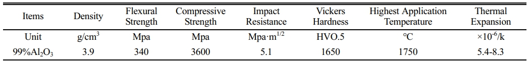
The chosen alumina material is a high-purity type with an alumina content of over 99%, suitable for high-temperature resistance. Its maximum operating temperature is up to 1750 °C, and it can work for a long time at 1600 °C, meeting the temperature requirements for glaze testing experiments. Moreover, this material has excellent wear resistance, strong corrosion resistance, high compressive strength, and low thermal expansion coefficient (detailed parameters shown in Table 1), all contributing to the stability of the support frame.
Manufacturing Process
Currently, alumina ceramics can be formed using various methods. Considering precision, difficulty, cycle, and cost, direct grinding of alumina industrial ceramics using computer numerical control (CNC) machining was chosen as the best manufacturing method for the support frame. This method ensures high precision and a short manufacturing cycle and is worthy of selection.
After the support frame parts are machined, they need to be assembled according to the drawings and tested in simulated use to ensure that the adjustable angles can be flexibly set while maintaining structural stability.
Glaze Scale Plate
Structural Design
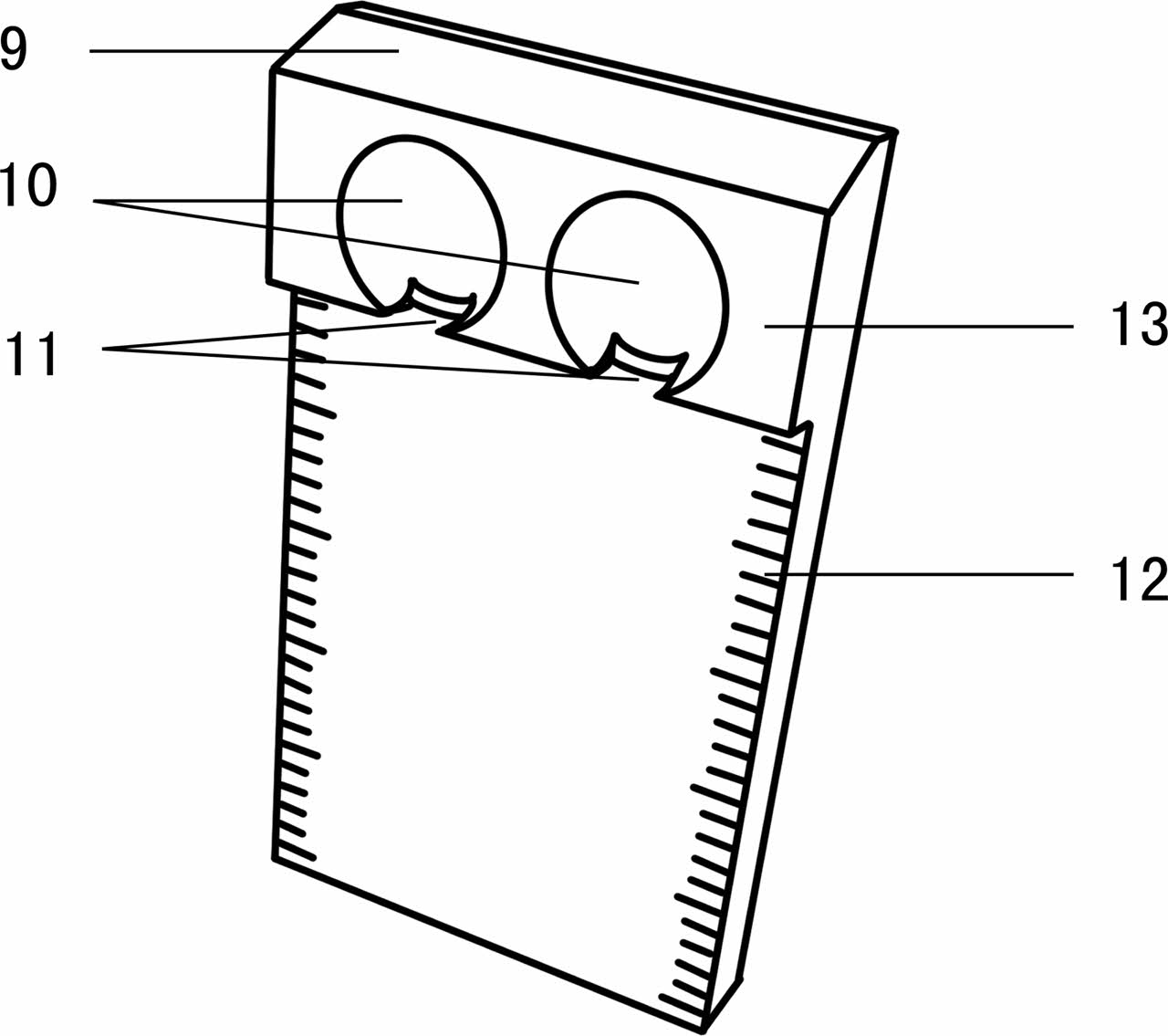
The glaze scale plate is designed to present glaze flow more intuitively and accurately, and it is used in conjunction with the angle-adjustable support frame as a glaze loading device. The schematic structure is shown in Fig. 2 and includes code position, glaze groove, glaze outlet, scale lines, and glaze platform.
The glaze scale plate is equipped with a glaze platform, and the glaze groove is located on the glaze platform, with a glaze outlet on one side of the glaze groove. The raised glaze platform has a grooved glaze groove for holding glaze samples. The opening design of the glaze groove allows glaze to flow out in the direction of the opening after high-temperature melting. Scale lines are provided on both sides of the glaze scale plate, starting from the horizontal position of the glaze outlet, to record the flow distance of the glaze during a test period, thus presenting the flowability of the tested glaze. A code position is provided on the top of the glaze platform to label the basic information of the tested glaze, facilitating the distinction between two glaze samples on the scale plate and allowing for easy retrieval and searching in the future. The glaze platform has two glaze grooves, enabling the simultaneous comparison test of two glaze samples.
The size of the glaze scale plate needs to be compatible with the angle-adjustable support frame and also consider the testing effect. If the size is too large or too thick, it may lead to waste, and if it is too thin, it may deform at high temperatures. To ensure good glaze testing results, after multiple experiments, it was determined that the blank size of the glaze scale plate should be no less than 40 mm × 100 mm, with a thickness of around 10 mm being optimal.
Material Selection
The material used to make the glaze scale plate was selected to match the tested glaze sample and guarantee no deformation at the testing temperature.
Manufacturing Process
The glaze scale plate can be made through either slip casting or press molding. In terms of precision, press molding is the preferred method. The water content and shrinkage rate of the slurry used in the process need to be controlled to ensure that the dried billet can be fired at 800 °C to 900 °C in a kiln, maintaining its integrity and meeting the experimental requirements.
|
Fig. 1 Structure diagram of angle adjustable bracket. |
|
Fig. 2 Structure diagram of glaze scale plate. |
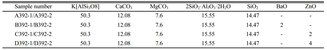
In this study, potassium feldspar, calcite, magnesium carbonate, calcined kaolin, quartz, barium sulfate, and zinc oxide were used as glaze raw materials [25-39]. The particle size was 325 mesh, and the glaze formulation is shown in Table 2.
The qualified glaze slurry was stirred evenly and dried. After that, 50 grams of dried glaze was mixed with 15 ml of water to form a paste. The glaze paste was then scooped with a Φ10 mm hemispherical sampler to create glaze balls weighing around 2 to 3 grams each. The glaze balls were weighed after drying to ensure a consistent weight of 2 grams. Multiple samples were prepared for the same glaze formulation to enable control experiments.
The control variable method was adopted in this experiment. Under the premise of keeping glaze formulation, fineness, weight, firing curve, and kiln placement consistent, the only variable was the testing angle. By changing the testing angle, the flowability variation of the glaze under the same experimental conditions was measured. The specific operation steps were as follows:
1) Place the dried glaze scale plate on a level operating table and place the prepared glaze ball in the glaze groove of the glaze scale plate. Add 1 ml of water to make the glaze ball adhere to the glaze scale plate. Prepare all the glaze scale plates to be tested in this manner.
2) Use a ceramic marker to mark the code information of the glaze sample to be tested at the code position of the glaze scale plate.
3) Open the kiln and place the tester support frame flat in a suitable position inside the kiln (if multiple sets of samples are tested simultaneously, arrange the kiln position carefully). Adjust the support frame to the desired test angle, ensuring that the guide groove of the second support plate is completely embedded in the angle groove of the base frame, ensuring the stability of the support frame. Gently place the prepared glaze scale plate on the support frame, making sure the back is tightly against the support rod and the bottom is against the support plate, as shown in Fig. 3.
4) Place pyrometric cones according to experimental needs to monitor the sintering temperature of the glaze sample.
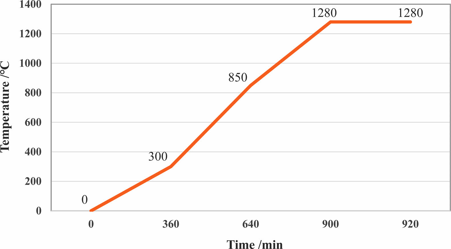
5) Set the firing curve of the kiln according to the glaze testing requirements (shown in Fig. 4).
6) Complete the firing process and take out the glaze scale plate after the kiln has cooled down.
7) Measure the length and width of the glaze sample flowing down from the glaze outlet and record the experimental data. The basic data of the experiment can be recorded using the scale lines on the glaze scale plate, and precise values can be measured using a vernier caliper.
8) Restore the experimental site, organize and analyze the experimental data, and write the experimental report.
|
Fig. 3 Illustration of the testing apparatus in use. |
|
Fig. 4 Temperature firing curve of glaze samples. |
The experimental results demonstrate that the glaze flows downward along the outlet after melting and presents different flow distances on the glaze scale plate. These distinct flow distances visually reflect the variations in glaze flowability due to different inclination angles after high-temperature melting, confirming the effectiveness of the designed glaze flow tester.
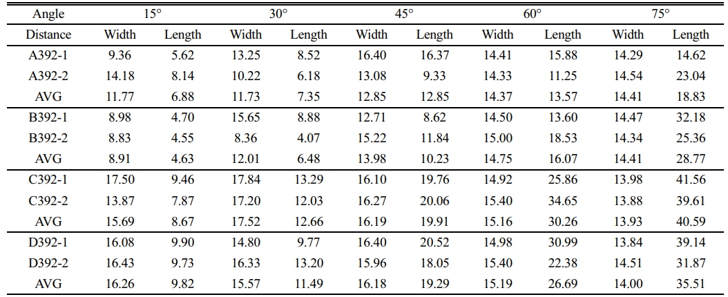
During the experiments utilizing the support frame, glaze flowability of the same formula at different inclination angles and different formula glazes at the same inclination angle were tested. Some of the measured results are detailed in Table 3. Observing the flow distances and their averages for glaze samples at different inclination angles reveals that the data exhibit regularity and good repeatability, indicating the data collection and measurements are reasonably accurate and reliable, ensuring the high credibility of the experimental results.
From the experimental data, it is evident that under consistent factors such as glaze formula, fineness, weight, firing curve, and kiln position, glaze flowability varies significantly with different inclination angles. The overall trend shows that within the same glaze formula, the flow distance is positively correlated with the inclination angle. However, for different formula glazes tested at the same inclination angle, flowability varies due to the different added components. Notably, components that significantly enhance glaze flowability do not exhibit a positive correlation with the amount of addition.
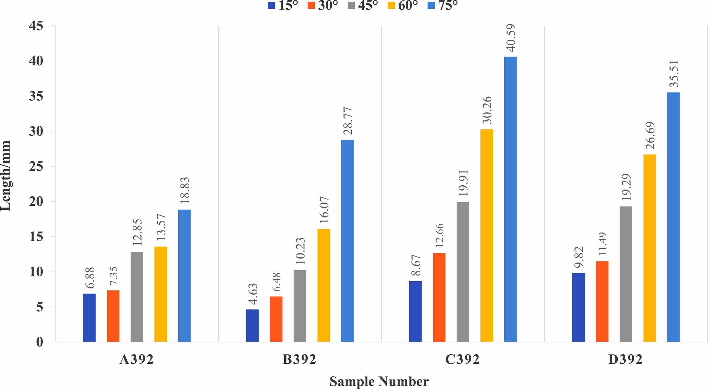
Analyzing the glaze flow distances that intuitively reflect glaze flowability (shown in Fig. 5), it can be observed that after firing the four glaze samples in the electric kiln at 1280 °C, sample C392 demonstrates the best flowability, while sample A392 exhibits the least flowability.
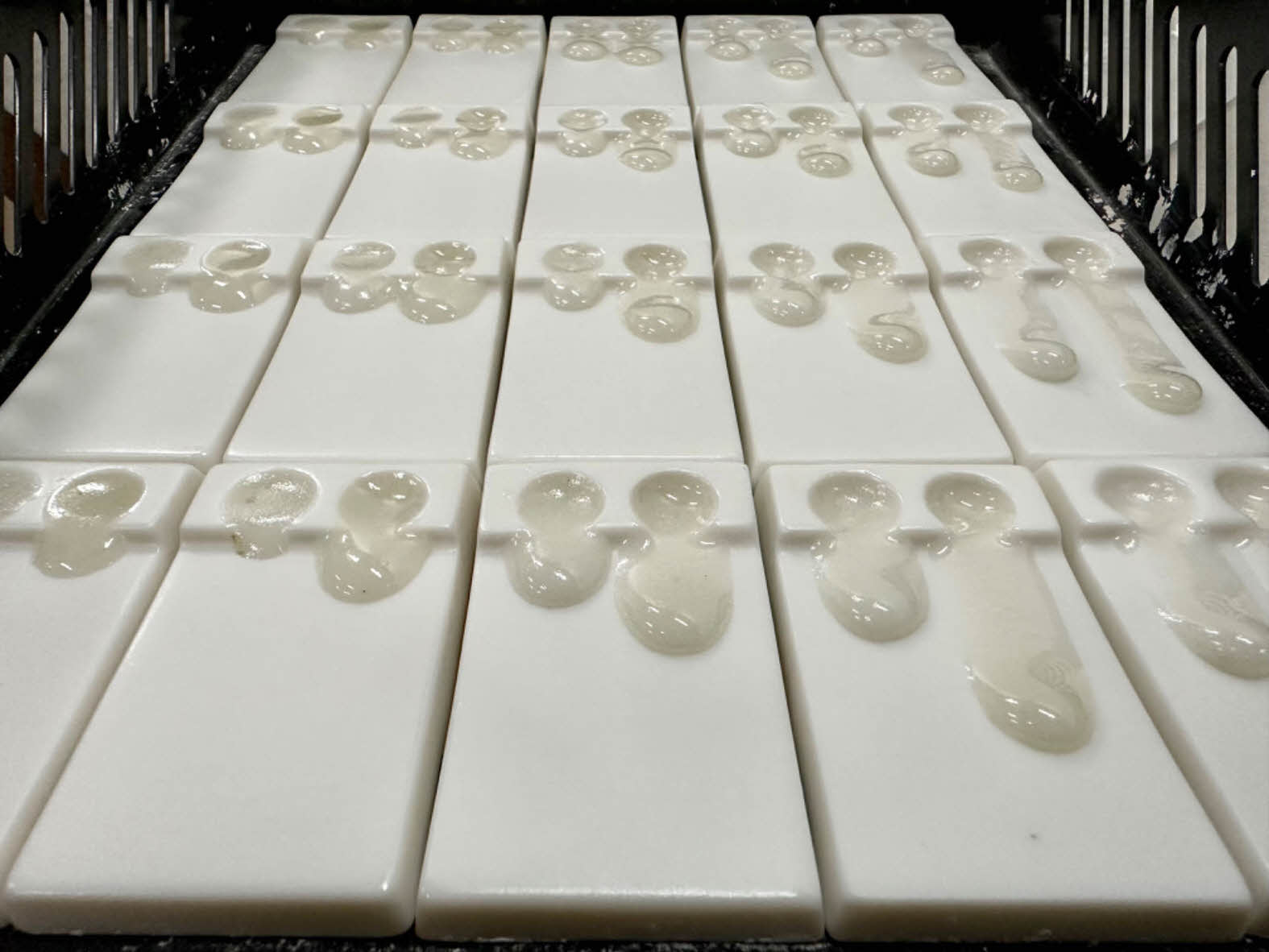
Observing the glaze surface effects (shown in Fig. 6), it is found that glazes with better flowability at different inclination angles do not necessarily yield better glaze surface effects. At 15° and 30° inclination angles, glaze flowability is relatively small, resulting in low glossiness. At 75° inclination angle, glaze flowability is high, but the glaze surface tends to be thinner, leading to bubbles and small cracks in some areas. On the contrary, at 45° and 60° inclination angles, glazes demonstrate better glaze surface effects while maintaining certain flowability.
Utilizing the glaze flow tester, further research can be conducted, such as studying the differences in glaze flowability for the same glaze at different inclination angles and optimizing the selection of inclination angles for different glazes. Compared to traditional glaze flow testers with fixed inclination angles, this glaze flow tester can better meet experimental needs.
In conclusion, this tester fulfills the requirements for conducting multiple experiments involving glaze flowability testing with adjustable inclination angles. Its design visually presents glaze flowability at different inclination angles. The testing experiments using this tester yielded significant results, accurately reflecting glaze flowability and providing reliability and comparability of the experimental data.
|
Fig. 5 Trend chart of high temperature flow length for glaze sample. |
|
Fig. 6 Results of glaze samples after high temperature firing. |
|
Table 3 Data table of flow distance for glaze samples in electric kiln at the firing temperature of 1280 ℃ (Unit/mm) |
In response to the need for glaze flowability testing at different inclination angles, this study modified the structure of the traditional glaze flow tester with fixed inclination angles while applying principles of traditional glaze performance testing. The result is the design of a glaze flow tester with adjustable angles, comprising an angle-adjustable support frame and a glaze scale plate. The tester achieves angle adjustment by moving the support plate of the angle-adjustable support frame into the angle groove. The double-sided support plate design enables control experiments, while the dual glaze grooves on the glaze scale plate facilitate simultaneous testing of glaze and reference glaze. The coding position on the top of the glaze scale plate allows for recording and retrieval of glaze sample information.
This tester not only meets the demand for glaze flowability testing at different inclination angles but also exhibits a sophisticated design, simple structure, quick installation, strong practicality, and recyclability, offering a sustainable technical solution for research related to glaze flowability in ceramics. It holds broad potential for applications in ceramic glaze design and development.
This work was supported by Open Project Fund of Key Laboratory of Traditional Heated-form Craft Technology and Digital Design, Ministry of Culture and Tourism of The People’s Republic of China (TK2021123104).
- 1. J.D. Li, R.B. Dai, China Ceram. Ind. 12[02] (2012) 15-20.
-

- 2. Y.G. Hu, China Ceram. 4 (2000) 15-19.
-
- 3. International Organization for Standardization. Vitreous and porcelain enamels - Determination of fluidity behaviour - Fusion flow test. ISO 4534:2010(E). Geneva. ISO (2010).
-
- 4. X.E. Zeng and J.P. Huang, China Standardization. 399[12] (2009) 37-39.
- 5. Z.L. Wang, China Ceram. 5 (1985) 55-57.
- 6. J.Y. Li, China Ceram. Ind. 24[01] (2017) 27-30.
-
- 7. J.H. Ji, R.F. Ni, B.L. Wu, and J.A. Feng, Foundry (Shenyang, China) 5 (1983) 44-46.
- 8. Y.Y. Zheng, J.D. Li, and C. Peng, Ceramics (Xianyang, China) 341[3] (2014) 57-59.
-
- 9. R.N. Cai, Y.Y. Zheng, and D.Y. He, Ceramics (Xianyang, China) 240[8] (2010) 57-58.
-
- 10. International Organization for Standardization, Monolithic (unshaped) refractory products - Part 4: Determination of consistency of castables. ISO 1927-4. Geneva. ISO (2012).
-
- 11. International Organization for Standardization, Coating powders - Part 11: Inclined-plane flow test. ISO 8130-11. Geneva. ISO (1997).
-
- 12. Light industry standard of the People's Republic of China, Test method for relative viscosity, relative liquidity and thixotropy of ceramic. QB/T 1545-2015. China (2015).
- 13. Standard of the Ministry of Machinery and Electronics Industry of the People's Republic of China, Test method for fluidity of glass powder for low fusion welding, SJ/T 3232.3-1989. China (1989).
- 14. Y. Long, Z.F. Yu, X. Wang, W.Q. Qian, and J. Li, Mater. Res. Appl. 17[3] (2023) 483-494.
-
- 15. R.F. Liang, C.Y. Dai, X.C. Liu, X.T. Zhang, X.Y. Fan, and Y.Q. Li, (2022-03-08). A kind of adjustable Angle fixed bracket for solid matter determination. CN215962364U. Fujian Province, China.
- 16. Z.M. Zhou, X.F. Song, Y.F. Chen, L.W. Tang, C. Liu, and Z.P. Xiao, Experimental Science and Technology 12[05] (2014) 1-2+7.
- 17. P.F. Wang, Q. Gao, CN214405428U. (2021-10-15). A kind of operation table support with adjustable height and Angle. Shanghai, China.
- 18. Y.B. Yang, CN213043624U. (2021-04-23). A solar energy Angle adjustable bracket. Tianjin, China.
- 19. L.Q. Xiao, X.H. Li, S.H. He, and D. Xiang, CN219204410U. (2023-06-16). Modular photovoltaic bracket with adjustable Angle. Hunan Province, China.
- 20. Z.H. Pang, Z.R. Feng, J.Y. Ma, X.L. Song, and G.Y. Pei, CN215990673U. (2022-03-08). A photovoltaic bracket with strong stability and adjustable tilt Angle. Guangdong Province, China.
- 21. W.L. Zeng, CN113758831A. (2021-12-07). A device for making removable resin fluidity test piece and its test method. Guangdong Province, China.
- 22. J.C. Ye, CN111721673B. (2022-08-09). A resin fluidity test fixture and its test method. Fujian Province, China.
- 23. J.L. Liu, Refractories & lime (Anshan, China) 300[02] (2008) 26-27.
-
- 24. C. Goegtas, N. Uenlue, A. Odabasi, L. Sezer, F. Cinar, S. Guener, and N. Eruslu, J. Ceram. Process. Res. 10[1] (2009) 43-48.
-
- 25. H. Shao, Image Technol. (Tianjin, China) 29[03] (2017) 80-82.
- 26. X.Q. Mao, Foshan Ceram. 23[07] (2013) 16-18.
- 27. G.F. Sun, Brick and tile (Xi’an, China) 11 (2012) 145-149.
-
- 28. X.Q. Mao, R.Q. Wu, T. Su, Z.J. Wu, and Y.F. Zhou, China Ceram. 08 (2008) 55-57.
-
- 29. H. Yildizay, J. Ceram. Process. Res. 24[2] (2023) 237-241.
-
- 30. Z.B. Ozturk and B. Yildiz, Glass Phys. Chem. 42 (2016) 257-262.
-
- 31. E. Bou, J. Garcia-Ten, R. Pérez, S. Arrufat, and G. Atichian, Bol. Soc. Esp. Ceram. 49 (2010) 271-278.
- 32. I.A. Levitskii and L.F. Papko, Glass Ceram. 67 (2011) 336-339.
-
- 33. I.A. Severenkov, E.V. Ustyugova, L.A. Alekseeva, T.V. Zaichuk, and Y.A. Spiridonov, Glass Ceram. 78 (2021) 259-263.
-
- 34. E. Kilinc, A.M. Bell, and P.A. Bingham, J. Am. Ceram. Soc. 104[8] (2021) 3921-3946.
-
- 35. D.M. Liu, J. Mater. Sci. 35 (2000) 5503-5507.
-
- 36. J.U. Eom, S. Kim, and J.H. Kim, J. Ceram. Process. Res. 22[5] (2021) 568-575.
-
- 37. N.M. Khalil, M.M.S. Wahsh, and A. Gaber, J. Ceram. Process. Res. 17[5] (2016) 478-484.
-
- 38. B.E. Yekta, P. Alizadeh, and L. Rezazadeh, J. Eur. Ceram. Soc. 27[5] (2007) 2311-2315.
-
- 39. D. Lee, H.S. Hong, H. Jeong, and S.S. Ryu, J. Ceram. Process. Res. 23[2] (2022) 149-153.
-
 This Article
-
2023; 24(5): 868-873
Published on Oct 31, 2023
- 10.36410/jcpr.2023.24.5.868
- Received on Jul 28, 2023
- Revised on Aug 13, 2023
- Accepted on Sep 17, 2023
Services
- Abstract
introduction
design of the tester
sample preparation
testing method and steps
experimental results
conclusion
- Acknowledgements
- References
- Full Text PDF
Shared
Correspondence to
- Ya-nan Xiu
-
China Academy of Art, Hangzhou, China
Tel : +86 13575784295 - E-mail: xyn-nanzi@163.com
Clean-Energy Research Institute(CRI), Hanyang University, 222, Wangsimni-ro, Seongdong-gu, Seoul, 04763, Korea
E-mail: jcpr@hanyang.ac.kr