


- Improvement of oxidation resistance property of C/SiCO nanoporous ceramic composites with TaSi2-MoSi2-ZrB2-borosilicate glass coating
Xiafei Lia,b, Junzong Fengb, Guozhu Zhaoa,* and Xingyu Wua
aAerospace Technology Institute, China Aerodynamics Research and Development Center, Mianyang, Sichuan 621000, China
bScience and Technology on Advanced Ceramic Fibers and Composites Laboratory, College of Aerospace Science and Engineering, National University of Defense Technology, Changsha, Hunan 410073, ChinaThis article is an open access article distributed under the terms of the Creative Commons Attribution Non-Commercial License (http://creativecommons.org/licenses/by-nc/4.0) which permits unrestricted non-commercial use, distribution, and reproduction in any medium, provided the original work is properly cited.
To improve the oxidation resistance property of C/SiCO nanoporous ceramic composites, TaSi2-MoSi2-borosilicate glass coatings and TaSi2-MoSi2-ZrB2-Borosilicate glass coatings were prepared on the surface of C/SiCO nanoporous ceramic composites through slurry brushing combined with graphite powder embedding sintering process. The coatings are smooth, flat, without cracks, and tightly bonded to the substrate material. A study was conducted on the thermal stability of coated samples in an air atmosphere at 1600 ℃ and the high-temperature oxidation mechanism was analyzed. The results show that the coating effectively improves the thermal stability of SiCO nanoporous ceramic composites, and the addition of ZrB2 further improves the oxidation resistance and ablation resistance of the coated samples. At high temperatures, the borosilicate glass in the coating displays a viscous flow state, and the SiO2 glass layer formed on the coatings surface serves as an oxygen barrier. At the same time, the coating has a particle reinforced glass structure inside, which avoid the growth and propagation of cracks and reduce oxygen diffusion channels effectively
Keywords: TaSi2-MoSi2-ZrB2-borosilicate glass coating, C/SiCO porous ceramics, high temperature resistance, oxidation resistance, ablation resistance
With continuous development of hypersonic flight vehicles, flying higher, faster, and more economically has become an eternal pursuit of humanity. This requires the continuous development of thermal protection technology to meet the needs of aircraft breaking through the thermal barrier. From the flight test experience of a series of hypersonic aircraft in the United States, such as HyFly, X-43A, X-51A, X-37B, etc. [1-5], it can be seen that reusable aerospace high-speed aircraft have a pressing demand for lightweight, non-ablative, high-temperature resistance, efficient thermal insulation, and excellent mechanical properties of integrated materials for thermal insulation [6-8].
At present, the Toughened Uni-piece Fiber Reinforced Oxidation-resistant Composite (TUFROC) [9], developed by the Ames Research Center of NASA, represents the most cutting-edge level in the field of new integrated thermal insulation materials internationally. TUFROC consists of a heat resistant cap coated with gradient coating on the surface and an internal insulation substrate. Among them, the internal insulation material is ceramic fiber rigid insulation tile, which has a very low thermal conductivity. The heat resistant cap is an antioxidant ceramic carbon insulation material (ROCCI). ROCCI is prepared by impregnating short cut carbon fibers with SiCO ceramic precursors and high-temperature cracking in an inert environment. Its combination with surface coatings can provide TUFROC with good high-temperature stability. The average density of TUFROC is 0.4 g/cm3, which is only a quarter of the density of reinforced carbon/carbon materials used on space shuttles, and the outer surface can withstand temperatures up to approximately 1700 ℃. TUFROC also overcomes the brittleness problem of pure ceramic insulation tiles and has excellent antioxidant and thermal shock resistance. At the same time, it has many advantages such as good mechanical properties, reusability, short manufacturing cycle, and low cost. In addition to TUFROC, other advanced integrated thermal insulation materials have also been developed. For example, a new type of integrated thermal insulation material, the Advanced Thermal Protection System (ATPS), has been developed by the Air Force Research Laboratory. ATPS is a composite material composed of a ceramic matrix composite and a ceramic fiber insulation layer.
The successful application of TUFROC has shown the development prospects of high-performance thermal insulation integrated materials for aerospace high-speed aircraft. In recent years, relevant researches have also been carried out internationally [10-22]. In the previous work, we selected SiCO porous ceramics as the matrix phase, impregnated polyacrylonitrile based carbon fibers, and prepared C/SiCO nanoporous ceramic composites through the sol-gel method [23]. We found that cracks or pores occured during the cracking of SiCO ceramic matrix and carbon fibers due to thermal expansion mismatch, providing a channel for oxygen to enter the material. Multiple composite SiCO precursors enable the material to form a more complete SiO2 layer under high-temperature oxidation environment, which can block oxygen from entering the material’s interior within a certain time range and improve the high-temperature resistance of C/SiCO. However, the oxidation resistance and temperature resistance of C/SiCO nanoporous ceramic composites still need further improvement.
To further improve the high temperature resistance of C/SiCO ceramic composites, TaSi2-MoSi2-borosilicate glass (TM-BG) coatings or TaSi2-MoSi2-ZrB2 borosilicate glass (TMZ-BG) coatings were prepared on the surface of C/SiCO using slurry sintering method. The phase composition and microstructure of the coatings were characterized, and the effects of coating composition and thickness on the oxidation resistance of SiCO nanoporous ceramic composites were studied. The results showed that the TM-BG and TMZ-BG coatings had a dense and uniform structure, and the oxidation resistance of SiCO nanoporous ceramic composites was improved significantly after coating.
Raw materials
Methyltrimethoxysilane (MTMS) and dimethyldiethoxy- silane (DMDES) were purchased from Wuhan Yi Hua Cheng Technology Development Co. (China). Ethanol (EtOH), ammonia (NH4OH) and nitric acid (HNO3) came from the Chemical Reagent Factory of Hunan Normal University. Hard carbon felts were obtained from Hunan Jiuhua Carbon High-tech Co. (China). TaSi2, MoSi2, ZrB2, Al2O3, B2O3, and SiO2 powders were all purchased from Sinopharm Chemical Reagent Co. (China). Deionized water was self-made. The purity is analytical pure and has not been further processed before use.
Preparation of Coatings
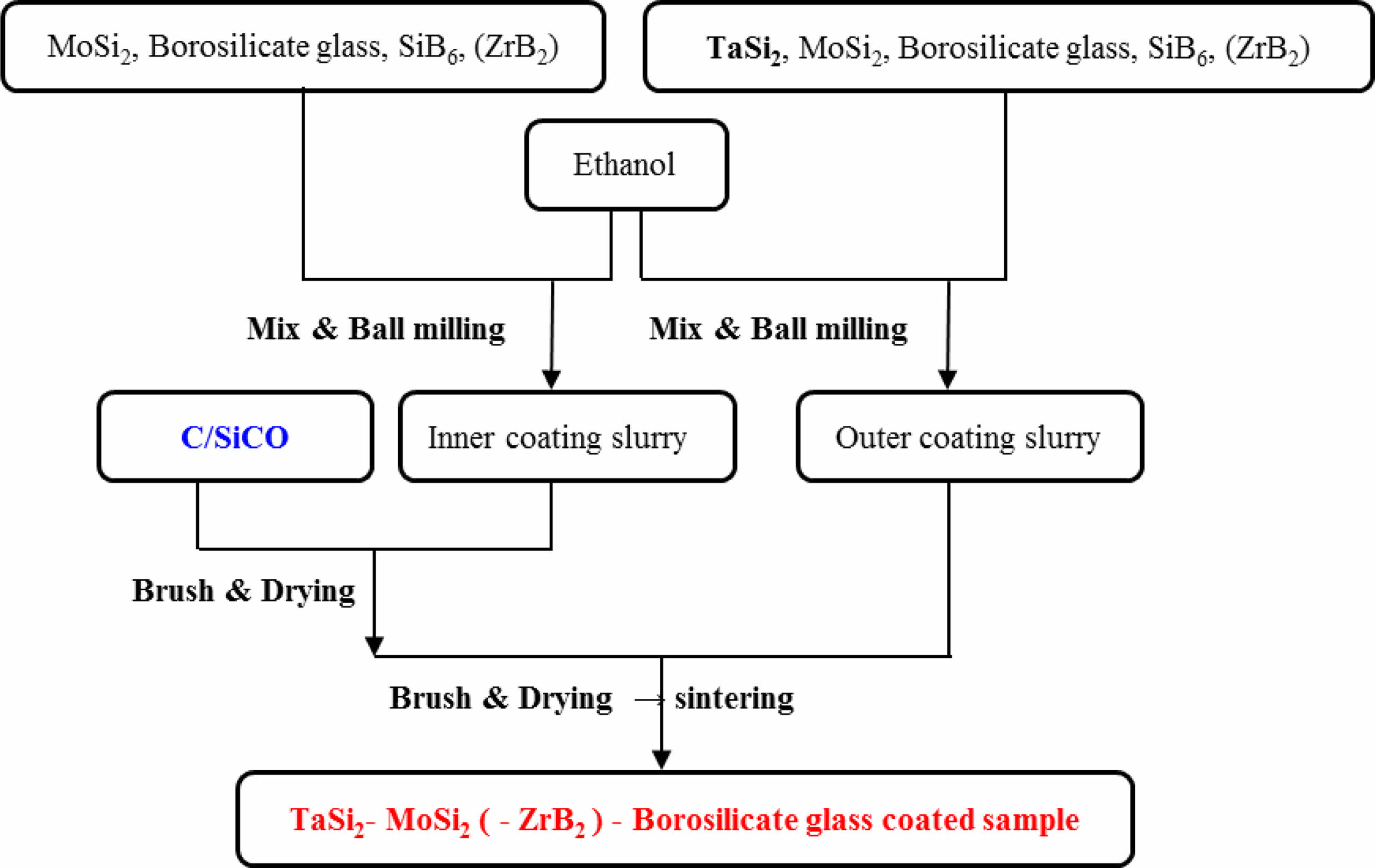
The process flow for preparing the coating is shown in Fig. 1, which mainly includes substrate pretreatment, coating slurry preparation, coating, drying, and high-temperature sintering. The details are as follows: Firstly, the SiCO nanoporous ceramic composites with densities of 0.55 g/cm3 were cut into a size of 15 mm × 15 mm × 15mm. Sample was polished and chamfered with 100-grit emery paper, and then dried in a 100 °C drying oven. Then, 5% Al2O3, 15% B2O3, and 80% SiO2 powders by mass ratio were mixed through ball mill for 4 hours. After sieving, they were poured into a crucible and placed in a muffle furnace. The muffle furnace was heated at a rate of 10 °C/min to 1500 °C and kept for 1.5 hours. After cooling in the furnace, the resulting glass block was ground into powder to obtain borosilicate glass powder. Next, according to the designed formula, the coating raw material powder was mixed with ethanol solution and placed in a ball milling tank. The coating slurry with particle size of 1-10 μm was obtained by ball milling at a speed of 220 r/min for 24 hours. Then, the coating slurry was evenly coated on the surface of the substrates using the brushing method, and the ethanol solution was evaporated in a 100 °C oven. The coating drying step was repeated multiple times to obtain coatings with different thicknesses. Finally, the SiCO nanoporous ceramic composites with anti-oxidant coating was prepared using graphite powder embedding sintering process in an air atmosphere with sintering time of 30 minutes and sintering temperature of 1315 °C.
Characterization
The X-ray diffraction spectrum (XRD) obtained from the German Bruker Model D8 Advance X-ray diffractometer to analyze the phase composition of the coating. After the sample was sprayed with gold, the microstructure was observed using Hitachi S4800 field emission scanning electron microscopy (SEM), and the local elemental composition and content of the sample were analyzed using a matching energy dispersive spectroscopy (EDS) analyzer. A muffle furnace was utilized to investigate the temperature resistance of the sample in an air atmosphere. The mass loss rate W is calculated by measuring the mass of the sample before and after different heat treatments, and the changes of its microstructure and phase composition are analyzed.

Among them, mbefore and mafter are the masses (g) of the samples before and after the temperature resistance test, respectively.
The DR6130 ablation instrument was used to evaluate the ablation resistance of the sample, and the real-time temperature of the cold surface (non-ablated surface) of the sample was recorded by dual-colorimetric infrared thermometer in parallel. The ablation resistance of the sample is characterized by its mass ablation rate Rm (g/s) and linear ablation rate Rd (mm/s), according to Eqs. (2) and (3) as follows [24]:

where m0 and m1 are the masses (g) before and after ablation, d0and d1are the center thickness (mm) before and after ablation, and t is the ablation time (s), respectively.
|
Fig. 1 Preparation process of TaSi2-MoSi2-(ZrB2-) borosilicte glass coated sample. |
Coating Composition and Structural Design
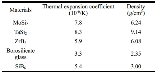
The oxidation rate of each structural unit in the C/SiCO nanoporous ceramic composites is different [25], and its surface coating should be able to prevent oxygen from diffusing to the interior of the base material. This requires that the coating raw materials should include glassy components with self-healing function, components with excellent high-temperature stability, and components with high radiance, as well as good physical and chemical compatibility between the substrates and the coating. In addition, for the design of the coating structure, it is necessary to maximize the bonding strength between the substrates and the coating, as well as the thermal expansion matching to prevent coating cracking. Table 1 lists the selected coating components and their thermal expansion coefficient and density. The borosilicate glass is made of B2O3, SiO2 and a small amount of Al2O3. The addition of Al2O3 can enhance the tightness of the glass structure, make the borosilicate glass have higher viscosity at high temperatures, and play the role of bonding other materials and self-healing microcracks [26]. MoSi2 and TaSi2 are metal silicide with high emissivity, which can significantly reduce the surface temperature of coating samples, and the glassy SiO2 generated under high-temperature oxidation atmosphere has self-healing function. The melting point of MoSi2 is up to 2030 °C, and the service temperature of TaSi2 is higher than that of MoSi2, which can endow the coating with good temperature resistance. SiB6 is a sintering additive used to increase the density of coatings. In addition, ZrB2 is a raw material with high melting point, good erosion resistance, and chemical inertness, which is expected to improve the temperature resistance of coating samples.
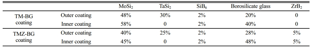
In order to improve the thermal expansion matching between the coating and the substrates, thereby reducing thermal stress at high temperatures, the coating is designed as a gradient structure. The outer coating has a high emissivity, which reduces the heat on the material’s surface and prevent oxygen from invading the inside of the material. The inner coating acts as a transition layer to adjust the thermal expansion matching of the substrates and the outer coating under high temperature environment, further protecting the substrates from oxidation. Table 2 lists the raw material mass ratios of the two coatings prepared in this paper. The coatings mainly composed of TaSi2, MoSi2, and borosilicate glass are labeled as TM-BG coatings, and the coatings added with ZrB2 are labeled as TMZ-BG coatings.
The amount of ethanol can control the viscosity of the coating slurry. If the viscosity of the slurry is too large, it is not easy to brush, and the surface of the sintered coating sample is relatively rough. If the viscosity of the slurry is too small, its strong fluidity will cause uneven coating, and the thickness of the sintered coating is small. The volume ratio of the grinding ball, mixed powder, and ethanol is 2:1:3 (TM-BG coating) and 2:1:5 (TMZ-BG coating). When brushing, it can be seen that the coating slurry is evenly and rapidly spread on the surface of the substrates, and the slurry has good wettability on the substrates. In this paper, apply the inner and outer coatings 4 times each are recorded as the brushing number of 8 cycles, and so on as 16 cycles and 24 cycles. After each brushing, it was placed in a 100 °C drying oven to evaporate the ethanol solution before proceeding with the next brushing. Repeated brushing can increase the thickness of the coating, thereby enhancing its protective effect on the substrates. However, excessively thick coatings may cause significant thermal stress due to mismatch with the thermal expansion of the substrates, resulting in cracking and peeling of the coating. In addition, both sintering temperature and sintering time have a great impact on the density of the coating [27-30]. If the sintering temperature is too high or the sintering time is too long, a large amount of gaseous oxidation products of borosilicate glass and metal silicide will volatilize, leading to defects such as bubbles or bulges in the coating; If the sintering temperature is too low or the time is too short, sufficient liquid phase cannot be formed during the sintering process, which affects the density of the coating surface. This work adopts the graphite powder embedding sintering method, with a sintering temperature of 1350 °C and a sintering time of 30 minutes. Figure 1 shows the preparation process of TaSi2-MoSi2-(ZrB2-) borosilicate glass coated sample.
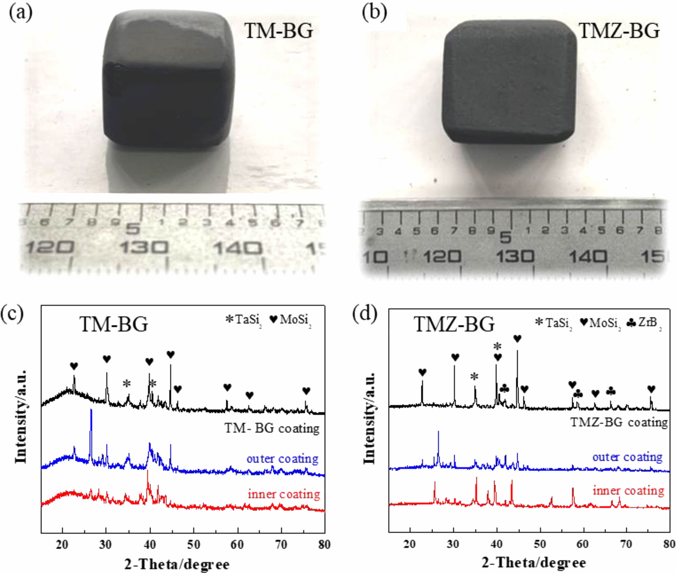
Figures 2(a) and (b) show macroscopic photos of TM-BG coated samples and TMZ-BG coated samples, respectively. The coating surface appears smooth and intact, with no signs of peeling, foaming, or cracking, and the shape of the samples remains intact after sintering. Figures 2(c) and (d) show the XRD patterns of the two coatings. It can be seen that the XRD patterns of the TM-BG coating only contain TaSi2 and MoSi2 phases, while the XRD spectra of the TMZ-BG coating include TaSi2, MoSi2, and ZrB2 phases, all of which are part of the coating slurry composition. The XRD patterns of both coatings show no oxide phase, indicating that although the coatings were sintered in an air atmosphere, the coatings retained their original composition due to the protective effect of graphite powder embedding. The failure to detect SiB6 may be because its low content, and the XRD patterns of both TM-BG and TMZ-BG coatings does not show any crystal characteristic peaks of borosilicate glass components, indicating that the glass phase in the coating dose not undergo crystal transformation, showing an amorphous form [31].
Microstructure of Coatings
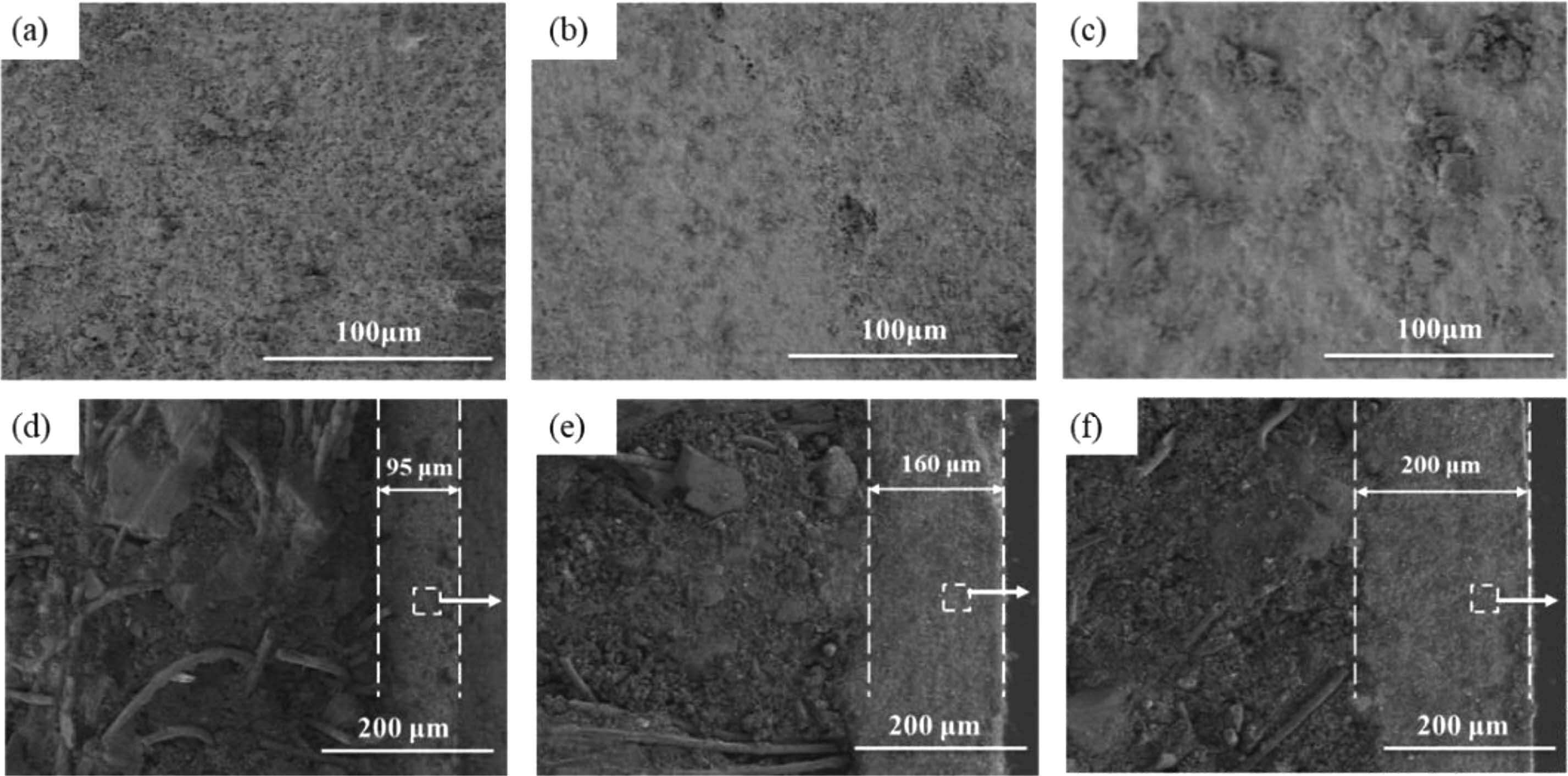
Figure 3(a-c) show the microstructure of the TM-BG coating surface with different brushing cycles, indicating that as the brushing cycles increase, the pores on the coating surface continue to decrease. The coating surface with 8 brushing cycles (Fig. 3a) has a large number of pores, which are not conducive to the oxidation resistance of the coating. From Fig. 3c, it can be seen that when the number of brushing cycle reaches 24, the pores on the coating surface have been completely closed, reflecting that sufficient glassy substances with certain viscosity has been formed at this time. Figure 3 (d-f) show the microstructure of the cross-section of TM-BG coatings with different brushing cycles. It can be seen that the coating thickness direction is intact without cracks, and there is no obvious boundary between the inner and outer coatings. The coating has a close bonding with the substrates, without any defects such as delamination or peeling, indicating good compatibility between the coating slurry and the substrates. As the number of brushing cycles increases from 8 to16 to 24, the coating thickness continues to increase, reaching 95 μm, 160 μm and 200 μm in sequence. The internal structure of the coating is uniform, with some irregular particles bonded together by the viscous flow state of borosilicate glass, and there are still some pores between the particles. According to the above XRD analysis, it can be speculated that under high temperature, the metal silicide and other particles in the raw materials are wrapped or bonded by glassy substances, forming a particle reinforced glass structure inside the coating, which can effectively avoid the growth and expansion of cracks and reduce the oxygen diffusion channel [32].
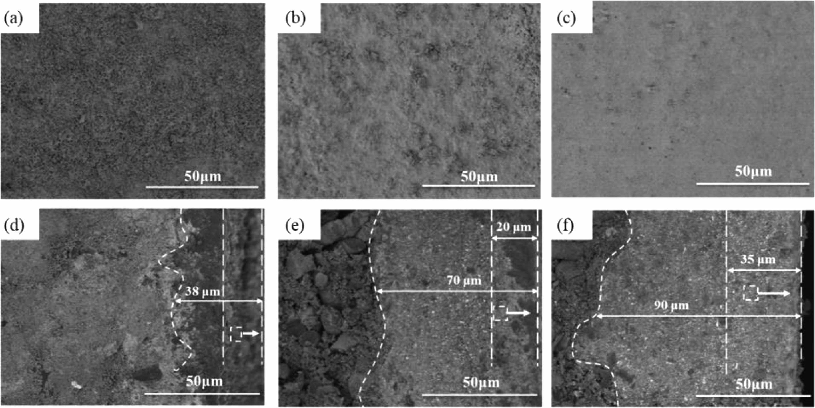
Figure 4(a-c) show the surface microstructure of TMZ-BG coatings with different brushing cycles. Similarly, with the increase of brushing cycles, the surface pores of the coating gradually decrease. There are a large number of small holes on the surface of the coating with 8 brushing cycles (Fig. 4a), and at this time, the coating is too thin, which easily leads to the formation of small holes. When the number of brushing cycle is increased to 16 (Fig. 4b), the pores on the coating surface are basically closed; The coating surface shown in Fig. 4c is relatively flat and the pores almost completely disappear when brushing 24 cycles. On the one hand, the borosilicate glass with a certain viscosity at high temperatures serves as a binder to fill between the particles of each component in the coating. On the other hand, it can self-heal microcracks and pores in the coating. Compared to the TM-BG coating in Fig. 3, the surface of the TMZ-BG coating is denser and smoother, indicating that the addition of ZrB2 can improve the density of the coating. Figure 4(d-f) show the microstructure of the TMZ-BG coating cross-section with different brushing cycles. It can be seen that there are no defects such as cracks or holes appear in the thickness direction of the coating, and the microstructure inside the coating is similar to that of the TM-BG coating. As the number of brushing cycles increase from 8 to 16 to 24, the thickness of the sintered coating continues to increase, with 38 μm,70 μm, 90 μm, respectively. The thickness of TMZ-BG coating is smaller than that of TM-BG coating with the same number of brushing cycles, because the TMZ-BG coating slurry has a higher ethanol content, with the aim of obtaining a flatter and smoother coating surface by reducing the slurry concentration. The inner coating penetrates into the substrates, which not only improves the bonding strength between the coating and the substrates, but also alleviates the thermal expansion difference between the substrates and the coating at high temperature to a certain extent. When the coating is brushed 8 cycles, there is a clear interface between the inner and outer coatings, and the outer coating contains some irregularly shaped pores, which are caused by the overflow of gaseous oxidation products. The gradient structure from the outside to the inside is also beneficial for improving the thermal expansion matching degree of the coating during high temperature sintering process, and preventing cracks in the coating due to residual thermal stress. As the number of brushing cycles increase, the porosity of the outer coating significantly decreases, and the structure of the inner and outer coatings tends to be consistent. Metal silicide and other particles in the TMZ-BG coating are bonded together by borosilicate glass, and the internal structure of the coating is uniform.
Temperature Resistance of Coatings
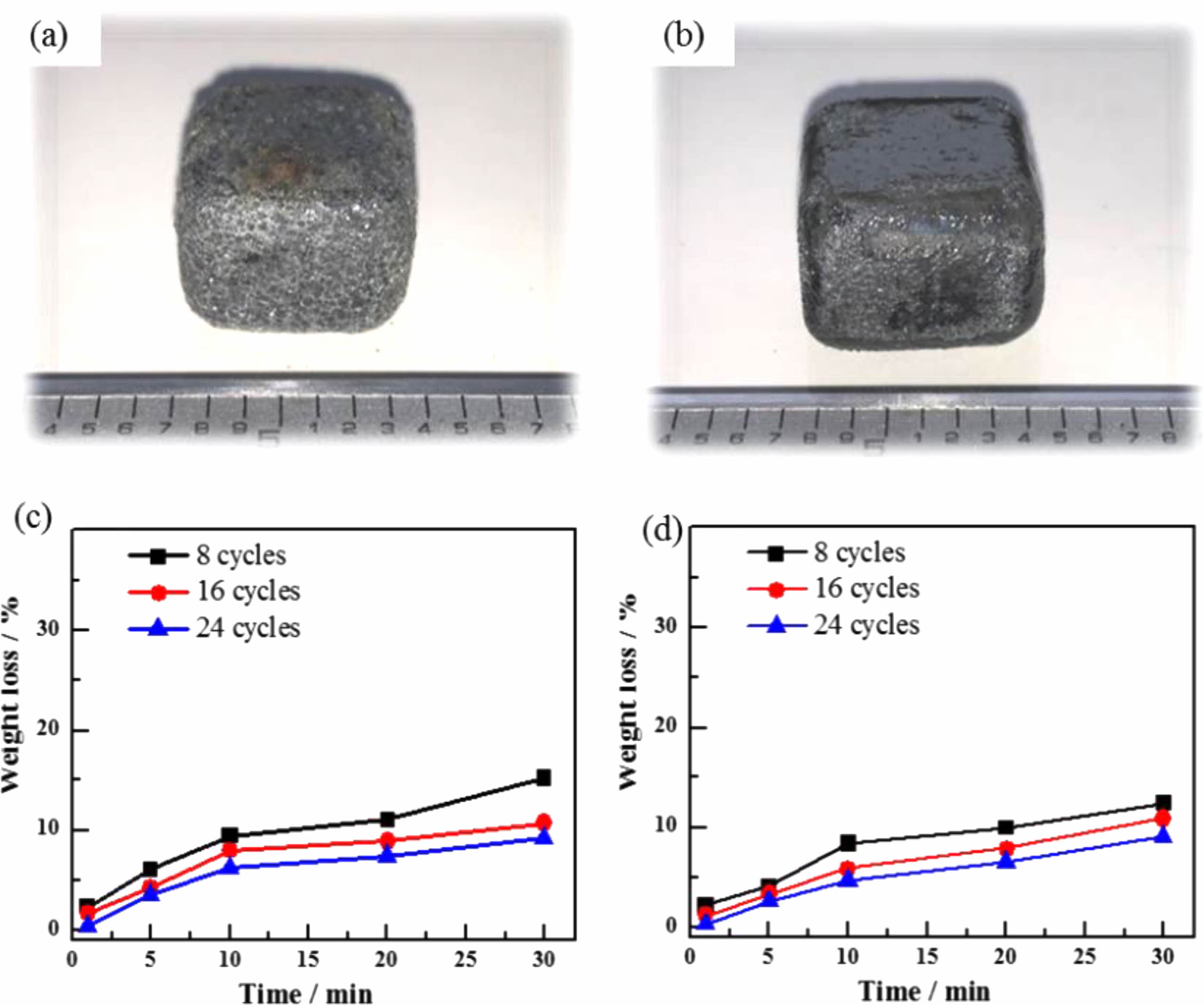
Figures 5(a) and (b) show the macroscopic morphology of the TM-BG and the TMZ-BG coated samples after heat treatment in an air atmosphere at 1600 °C for 30 minutes. It can be seen that the coating is completely covered on the surface of the substrates without peeling off, but the surface of the TM-BG coating sample is uneven and filled with small bubbles (Fig. 5a). The surface of the TMZ-BG coating sample remains basically smooth and flat (Fig. 5b), indicating that ZrB2 can play the role of stabilizer. The addition of ZrB2 improves the compatibility between the substrates and the coating, enhancing the temperature resistance of the coating under aerobic conditions.
Figures 5(c) and (d) show the mass loss rates of the TM-BG coated samples and the TMZ-BG coated samples after heat treatment at 1600 °C for different times in an air atmosphere. It can be seen that the mass loss rates of coated samples after heat treatment under the same conditions decrease with the increase of brushing cycles. This is because the increase of coating thickness can reduce the rates of thermal damage and oxidative damage at high temperatures, thereby effectively enhancing the protective effect of the coating on the substrates. In addition, under the same conditions, the mass loss rate of TMZ-BG coated samples after heat treatment is lower. TMZ-BG coating has a better protective effect on the substrates than that of TM-BG coating, proving that adding ZrB2 helps to improve the temperature resistance of the coating.
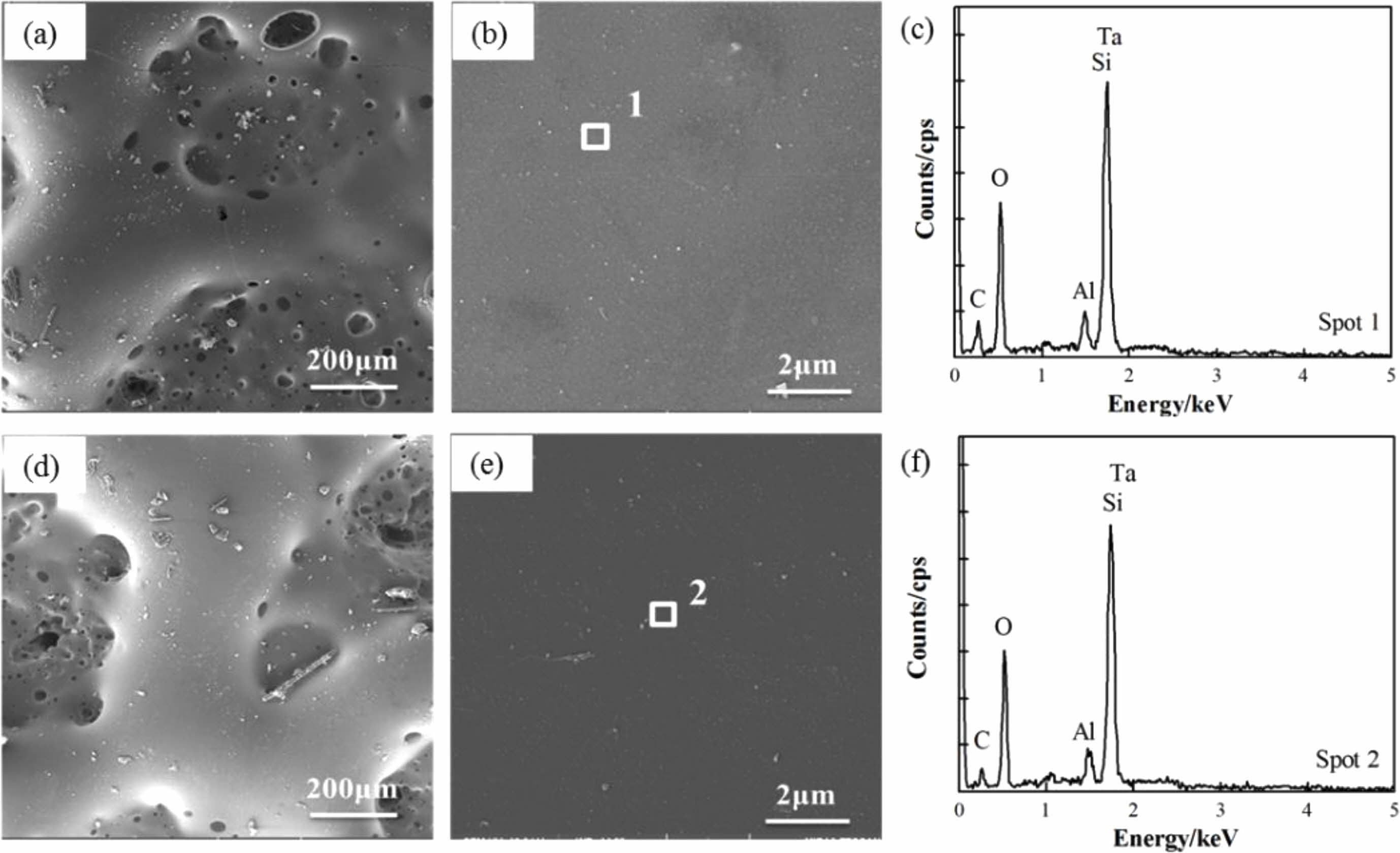
Furthermore, our previous research results on the substrates showed that after 20 minutes of heat treatment at 1600 °C in an air atmosphere, the mass loss rate of C/SiCO was 22.3% [8]. After coating with TM-BG coating, the mass loss rate of the material under the same heat treatment conditions decreased to 7.42%. The TMZ-BG coated sample had a smaller mass loss rate after heat treatment, which was 6.48%. It can be seen that both coatings can improve the temperature resistance of SiCO nanoporous ceramic composites to a certain extent, and the TMZ-BG coating has a more significant improvement on the temperature resistance of the substrates. Hence, the TMZ-BG coating has a better protective effect on the substrates than the TM-BG coating. Figure 6 shows the surface microstructure and elemental energy spectrum analysis of coatings after heat treatment in an air atmosphere at 1600 °C for 30 minutes. From SEM photos, it can be seen that there are some small pores and bulges on the surface of the coating after heat treatment. EDS analysis was conducted on the dense areas of the coating surface observed at higher magnification. The elemental composition at points 1 and 2 include C, O, Al, Ta, and Si, among which O, Al, and Si belong to borosilicate glass. The borosilicate glass in the coating exhibits a viscous flow state at high temperatures, and SiO2 is generated after oxidation of TaSi2, MoSi2, and SiB6. SiO2 has an extremely low oxygen diffusion rate and can serve as an oxygen barrier layer to provide better protection for the substrates during short heat treatment times [30]. However, as the heat treatment time prolongs, gaseous oxidation products (such as MoO3) generated under high temperature aerobic environment evaporate and overflow onto the coating surface, resulting in pores on the glass film. SiO2 is insufficient to bridge these pores, providing a channel for oxygen to invade the interior of the coatings. Therefore, after a certain period of high temperature heat treatment in the air atmosphere, the intensification of oxidation reaction weakens the protective effect of the coating on the substrates. It can be inferred that the coating surface after 30 minutes of heat treatment is embedded with Ta2O5 particles in the glass phase. In addition, the absence of Mo element detected in the energy spectrum confirms the volatilization of MoO3.
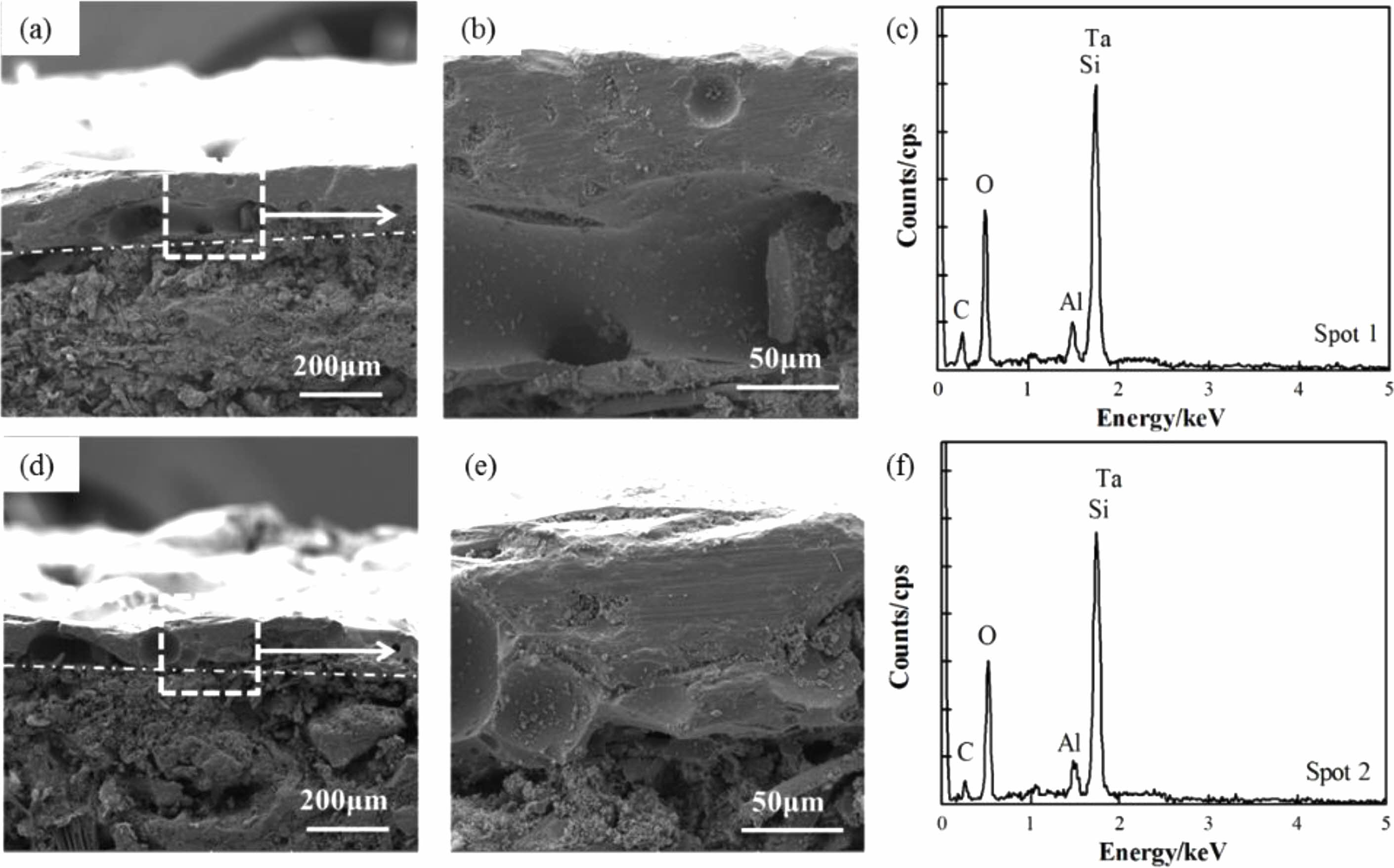
Figure 7(a, b, d, e) show cross-sectional SEM images of coatings after heat treatment in an air atmosphere at 1600 °C for 30 minutes. It can be observed that the substrates and coating still maintain good adhesion, and the coating structure is complete and dense, without any micropores or microcracks. The pores and cracks on the coating surface do not penetrate the entire coating in the thickness direction. Borosilicate glass has a certain fluidity when the temperature is above 1000 °C. It can not only form a layer of SiO2 film on the surface of the coating to prevent oxygen from diffusing internally, but also the viscous flow state of SiO2 at high temperatures can bridge some cracks and pores in the coating, allowing internal defects in the coating to self-heal. Therefore, the coating cross-section is relatively dense after heat treatment.
The XRD patterns of the TM-BG (c) and the TMZ-BG (f) coating surface after heat treatment in an air atmosphere at 1600 °C for 30 minutes are shown in Figure 8. The phase composition of the two coatings after heat treatment is the same, including SiO2 phase and Ta2O5 phase. Compared with the original phase composition of the coating surface (Fig. 2), after a prolonged heat treatment at 1600 °C, the original component of the coating, TaSi2, was oxidized to Ta2O5, and MoSi2 was oxidized to MoO3. However, MoO3 had a higher vapor pressure and would evaporate when the temperature exceeded its melting point (795 °C), so MoO3 was not detected in the XRD patterns. The oxidation of TaSi2, MoSi2, and SiB6 all produces SiO2, and the viscous glass phase will precipitate crystals to form SiO2 phase during the cooling process. From the XRD patterns, it can be seen that the crystalline characteristic peak of SiO2 is very prominent, indicating a large proportion of SiO2 phase in the coating. The characteristic peak of ZrB2 or its oxides was not detected in the graph of Figure 8f, because the content of ZrB2 in the coating components is relatively low. In addition, there are no peaks in the patterns for the components B2O3 and Al2O3 of borosilicate glass, indicating that the glass still exists in an amorphous form at high temperatures.
Ablation Resistance of Coatings
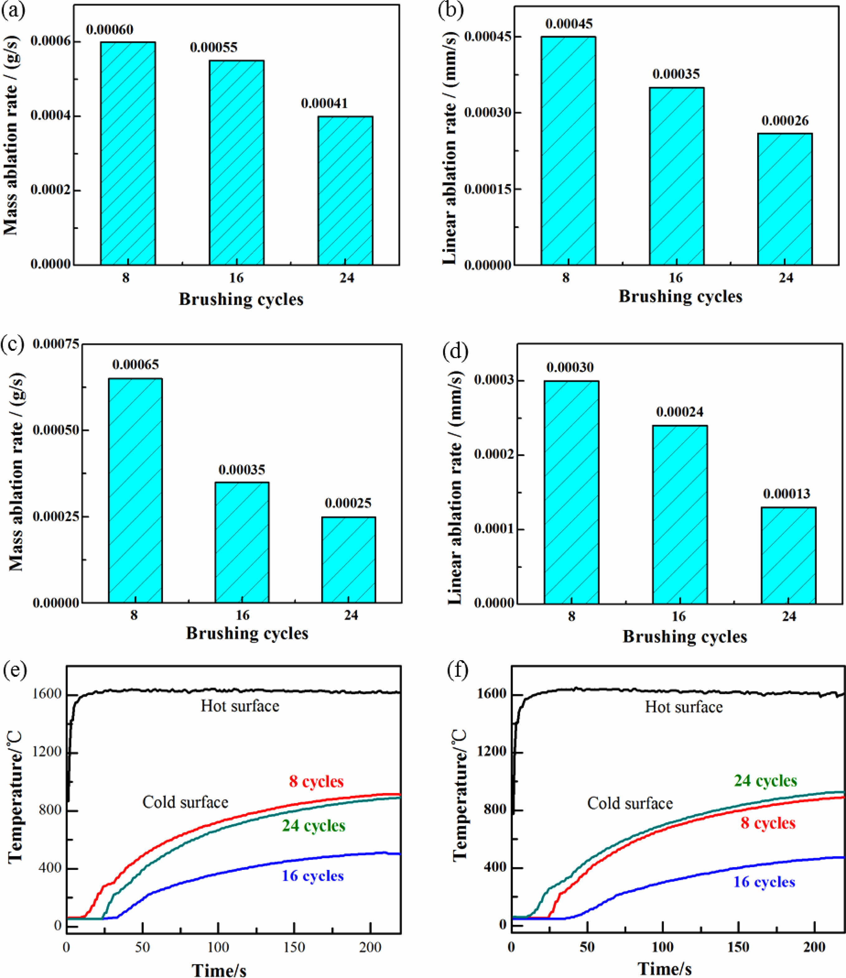
Figures 8(a-d) show the ablation rate of the TM-BG and TMZ-BG coated sample after being ablated at 1600 °C for 200 seconds. It is observed that with the increase of brushing cycles, both mass ablation rate and linear ablation rate of the coated sample continue to decrease, indicating that an increase in coating thickness is beneficial for enhancing the ablation resistance of the sample. The ablation resistance of the sample is not only affected by the thermal expansion matching between the coating and the substrates at high temperatures, but also by the ablation degree of oxygen acetylene flame on the sample in the experiment. Under the same ablation conditions, the thicker the coating, the better the protective effect of the substrates. In addition, by comparing Figures (a) (b) and (c) (d), it can be found that the mass ablation rate and linear ablation rate of TMZ-BG coated sample are both lower than that of TM-BG coated sample, indicating that TMZ-BG coating is more stable under oxyacetylene flame, and the TMZ-BG coated sample has better ablation resistance. According to the research on the ablation resistance of C/SiCO nanoporous ceramic composites shown in supporting information, its mass ablation rate and linear ablation rate is 5×10⁻⁴ g/s and 2.1×10⁻³ mm/s, respectively. When the coating is brushed 24 cycles, the mass ablation rate and linear ablation rate of TM-BG coated sample decreased by 18% and 88% under the same ablation conditions, and that of TMZ-BG coated sample decreased by 50% and 94%. It can prove that the coating greatly enhances the ablation resistance of C/SiCO ceramic composites.
The surface temperature curves of TM-BG and TMZ-BG coated samples during the ablation process at 1600 °C /200 s are shown in Figs. 8(e) and (f). It can be seen that the cold surface temperature of the coated samples is the lowest when the number of brushing cycles is 16. Among them, the cold surface temperature of the TM-BG coated sample is 509 °C, while the TMZ-BG coated sample has a lower cold surface temperature of 473 °C. When the coating is brushed 8 cycles, the sintered coating was relatively thin and could not resist the ablation of oxygen acetylene flame during service time, leading to oxidation of the substrates, which weakened its insulation performance. Therefore, the cold surface temperature of the coated sample is higher. When the number of brushing cycles is 16, the thicker coating provides effective protection for the substrates under the ablation of 1600 °C oxygen acetylene flame. On the one hand, it can give full play to the insulation performance of the substrates; on the other hand, the coating with higher radiance will dissipate the surface heat, reducing the heat transfer to the substrates, so the cold surface temperature of the coated sample is lower. However, when the coating is brushed 24 cycles, the thicker coating may experience thermal expansion mismatch with the substrates under the ablation of high-temperature oxygen acetylene flames. The thermal stress action causes the microcracks generated by the coating to provide a channel for oxygen to enter the interior of the material, and also causes more heat to be transferred to the cold surface, causing temperature rise.
|
Fig. 2 Photographs of the coated sample (a, b) and XRD patterns of the coating (c, d). |
|
Fig. 3 Surface (a,b,c) and cross-sectional (d,e,f) SEM images of the TM-BG coating with different brushing cycles: (a,d) 8 cycles, (b,e) 16 cycles, (c,f) 24 cycles. |
|
Fig. 4 Surface (a,b,c) and cross-sectional (d,e,f) SEM images of the TMZ-BG coating with different brushing cycles: (a,d) 8 cycles, (b,e) 16 cycles, (c,f) 24 cycles. |
|
Fig. 5 Photographs and weight loss of the TM-BG coated sample (a,c) and the TMZ-BG coated sample (b,d) after heating in air at 1600 °C. |
|
Fig. 6 Surface SEM images of coating and its energy spectrum (c, f) after heating in air for 30 min at 1600 °C (a, b) TM-BG coating, (d, e) TMZ-BG coating |
|
Fig. 7 Cross-sectional SEM images of coating and its XRD patterns after heating in air for 30 min at 1600 °C (a, b, c) TM-BG coating, (d, e, f) TMZ-BG coating. |
|
Fig. 8 Mass and linear ablation rate of the TM-BG coated sample (a,b) and the TMZ-BG coated sample (c,d) with different brushing cycles after ablation. Surfaces temperature curves of the TM-BG coating (e) and the TMZ-BG coating (f) during ablation. |
TaSi2-MoSi2(-ZrB2)-borosilicate glass coatings were prepared on the surface of C/SiCO nanoporous ceramic composites by slurry brushing combined with graphite powder embedding sintering process in this work. As the number of brushing cycles increase, the thickness of coating increase constantly and the coating bonds more closely to the substrates. Metal silicide and other particles inside the coating are wrapped or bonded by glassy substances, following a particle reinforced glass structure formation, which can avoid crack growth and expansion and reduce oxygen diffusion channels.
The formation of a SiO2 film on the coated surface in a high-temperature aerobic environment can effectively prevent the diffusion of oxygen into the interior. Moreover, the viscous flow state of SiO2 can self-heal internal defects in the coating. Both TM-BG coating and TMZ-BG coating can provide high temperature oxidation protection for C/SiCO ceramic composites, and an increase in the coating thickness can improve the temperature resistance of the material. Under aerobic environment at 1600 °C, the ablation rate and the mass loss rate after heat treatment of TMZ-BG coated samples are smaller than that of TM-BG coated samples. The surface of TMZ-BG coated samples remains basically smooth and flat after a long period of heat treatment, indicating that the addition of ZrB2 can play a good stabilizing role. Therefore, TMZ-BG coating has a more significant improvement in the oxidation resistance and ablation resistance of SiCO ceramic composites.
Thanks to eceshi (www.eceshi.com) for the SEM analysis and Shiyanjia Lab (www.shiyanjia.com) for the XRD test.
The authors declare no conflict of interest.
- 1. L. Marshall, C. Bahm, G. Corpening, and R. Sherrill, AIAA Paper 2005-3336 (2005).
-

- 2. R.T. Voland, L.D. Huebner, and C.R. McClinton, Acta Astronautica 59 (2006) 181-191.
-
- 3. C. Bahm, E. Baumann, J. Martin, D. Bose, R. Beck, and B. Strovers, AIAA Paper 2005-3275 (2005).
-
- 4. J. Hank, J. Murphy, and R. Mutzman, AIAA Paper 2008-2540 (2008).
-
- 5. A.C. Grantz, AIAA Paper 2011-7315 (2011).
-
- 6. R. Seniz, J. Ceram. Process. Res. 24 (2023) 736-741.
-
- 7. S.H. Lee, J. Ceram. Process. Res. 22 (2021) 517-520.
-
- 8. J. Liu, Z. Lu, Y. Zhou, J. Zhang, and G. Lyu, J. Ceram. Process. Res. 24 (2023) 285-307.
-
- 9. D.A. Stewart, and D.B. Leiser, AIAA Paper 2006-7945 (2006).
-
- 10. K. Lu, D. Erb, and M. Liu, J. Mater. Chem. C 4 (2016) 1829-1837.
-
- 11. M.M. Alejandra, P. Isabel, T. Aitana, J.I. Robla, L.D. Aurora, and R. Juan, Sol. Energy 173 (2018) 256-267.
-
- 12. T. Xu, Q. Ma, Y. Wang, and Z. Chen, Ceram. Int. 40 (2014) 13787-13792.
-
- 13. T. Xu, Q. Ma, and Z. Chen, Mater. Sci. Forum 686 (2011) 419-422.
-
- 14. T. Xu, Q. Ma, and Z. Chen, Ceram. Int. 38 (2012) 605-611.
-
- 15. M. Niu, H. Wang, J. Chen, L. Su, D. Wu, and A. Navrotsky, J. Am. Ceram. Soc. 100 (2017) 3693-3702.
-
- 16. S. Dong, H. Wen, Q. Zhou, and Y. Ding, J. Ceram. Process. Res. 10 (2009) 278-285.
-
- 17. Q.M. Wang, J. Gong, C. Sun, H.W. Lee, and K.H. Kim, J. Ceram. Process. Res. 12 (2011) 259-264.
-
- 18. C. Ozturk, and T. Demircan, J. Ceram. Process. Res. 21 (2020) 433-441.
-
- 19. K. Nam, H. Jeong, J. Kim, and S. Ahn, J. Ceram. Process. Res. 17 (2016) 1188-1191.
-
- 20. Y. Kim, C. Jang, J. Choi, and E.S. Kim, J. Ceram. Process. Res. 15 (2014) 277-280.
-
- 21. K.J. Hwang, K.H. Kim, Y.C. Lee, J.T. Hwang, and H. Lee, J. Ceram. Process. Res. 20 (2019) 169-172.
-
- 22. D.H. Lee, B. Jang, C. Kim, and K.S. Lee, J. Ceram. Process. Res. 20 (2019) 499-504.
-
- 23. X. Li, J. Feng, Y. Jiang, and J. Feng, Ceram. Int. 45 (2019) 17064-17072.
-
- 24. Z. Ma, W.Z. Li, L.H. Gao, and B. Wen, Rare Metal. Mater. Eng. 46 (2017) 2097-2101.
-
- 25. T. Xu, Q. Ma, and Z. Chen, J. Mater. Sci. Eng. A 530 (2011) 266-270.
-
- 26. X. Li, J. Feng, Y. Jiang, H. Lin, and J. Feng, RSC Adv. 8 (2018) 13178-13185.
-
- 27. B. Du, C. Hong, S. Zhou, L. Chen, and X. Zhang, J. Eur. Ceram. Soc. 36 (2016) 3303-3310.
-
- 28. B. Du, C. Hong, A. Wang, and S. Zhou, Ceram. Int. 44 (2018) 563-570.
-
- 29. B. Du, C. Hong, X. Zhang, A. Wang, Ceram. Int. 44 (2018) 3505-3510.
-
- 30. B. Du, S. Zhou, X. Zhang, and C. Hong, Surf. Coat. Technol. 350 (2018) 146-153.
-
- 31. G. Shao, Y. Lu, X. Wu, J. Wu, and S. Cui, Appl. Surf. Sci. 416 (2017) 805-814.
-
- 32. F. Yu, D. Gu, Y. Zheng, Y. Luo, X. Li, H. Chen, and L. Guo, J. Alloys Compd. 729 (2017) 453-462.
-
- 33. Y. Yu, R. Luo, Q. Xiang, Y. Zhang, and T. Wang, Surf. Coat. Technol. 277 (2015) 7-14.
-
 This Article
-
2023; 24(5): 816-826
Published on Oct 31, 2023
- 10.36410/jcpr.2023.24.5.816
- Received on Jul 1, 2023
- Revised on Jul 25, 2023
- Accepted on Jul 28, 2023
Services
- Abstract
introduction
experiment
results and discussion
conclusion
- Acknowledgements
- Conflict of Interest
- References
- Full Text PDF
Shared
Correspondence to
- Guozhu Zhao
-
Aerospace Technology Institute, China Aerodynamics Research and Development Center, Mianyang, Sichuan 621000, China
- E-mail: zhaoguozhu@cardc.cn
Clean-Energy Research Institute(CRI), Hanyang University, 222, Wangsimni-ro, Seongdong-gu, Seoul, 04763, Korea
E-mail: jcpr@hanyang.ac.kr