


- Effect of heat treatment on microstructure and tensile strength of KD-II SiC fibers in argon and oxidation atmosphere
Huan Yin, Fenghao Yang, Guangmin Hu* and Maozhong Yi
State Key Laboratory for Powder Metallurgy, Central South University, Changsha 410083, P.R. China
This article is an open access article distributed under the terms of the Creative Commons Attribution Non-Commercial License (http://creativecommons.org/licenses/by-nc/4.0) which permits unrestricted non-commercial use, distribution, and reproduction in any medium, provided the original work is properly cited.
The polycarbosilane derived KD-II SiC fibers were heat treated in argon atmosphere at temperatures from 1000 °C to 1800 °C and in oxidation atmosphere at temperatures from 1000 °C to 1500 °C for 1 hour, respectively. The effect of heat treatment on microstructure of all fibers were characterized by X-ray diffraction, scanning electron microscopy, transmission electron microscopy, X-ray photoelectron spectroscopy and Atomic Force Microscopeand, and the tensile strength of fibers were evaluated by monofilament tensile test and Weibull model. The results reveal that the fibers of heat treatment in argon atmosphere can maintain their original tensile strength (~2.5 GPa) up to the temperature at 1200 °C. After that, their tensile strength starts to decline, especially when the temperature exceeds 1400 °C a sharp strength degradation is observed. Through detailed characterization, we find that the reasons for the strength degradation of fibers heat treatment in argon atmosphere include the appearance of surface defects, growth of β-SiC grains and decomposition of SiCxOy amorphous phase. Correspondingly, the fibers heat treated in oxidation atmosphere have lower tensile strength compared with those fibers heat treatment in argon atmosphere at the same temperature. Furthermore, their tensile strength starts to degenerate at 1000 °C, and only 30% of original strength is retained when the temperature reached 1500 °C. Obviously, for fibers heat treatment in oxidation atmosphere, their tensile strength degradation starting temperature is lower and degradation speed is faster than those fibers heat treatment in argon atmosphere. This can be attributed to the interface stress existed between silica layer with internal fibers, the surface cracks caused by the thermal stress and the growth of β-SiC grains
Keywords: SiC fibers, Heat treatment, Microstructure, Tensile strength, Argon atmosphere, Oxidation atmosphere
Currently, ceramic matrix composites (CMCs) have been regarded as potential structural materials for applications in defense equipment, aviation and nuclear energy field [1-5]. This is because CMCs have several outstanding features including good thermal stability, excellent stiffness and high fracture toughness [6-11]. The polycarbosilane derived SiC fibres are widely used to reinforce the CMCs owing to their high tensile strength, excellent high temperature resistance and good oxidation resistance [12-15]. During the process of manufacturing SiC-CMCs (SiC fibers reinforced CMCs), the SiC fibers would experience a series of complex high temperature heat treatment under inert atmosphere [16-18]. Then, SiC fibers are also be exposed to high temperature oxidizing environment in the applications of SiC-CMCs [19, 20]. Thus, it is extremely important to investigate the effect of high temperature heat treatment on the microstructure and tensile strength of SiC fibers both in inert and oxidizing atmosphere. Many investigators have worked on the changes in microstructure and mechanical properties of the SiC fibers in various environments including air, Ar, N2, O2 and vacuum, and at various temperatures and pressures [21-27]. Furthermore, these previous researches are mostly focused on the Nicalon, Hi-Nicalon, Hi-Nicalon Type-S and Tyranno SA SiC fibers. Recently, a new type of SiC fibers (KD-II SiC fibers) which are manufactured by the National University of Defence Technology (NUDT, China) have attracted much attention. Shiyi Cao et al. [28] studied the influence of heat treatment on the microstructure and tensile strength of KD-II SiC fibers in an Ar atmosphere. They believed that the tensile strength degradation of KD-II SiC fibers were caused by β-SiC grain growth, the residual tensile stresses and the surface flaws. Liang Li et al. [29] studied the effect of heat treatment on the microstructure and mechanical properties of KD-II SiC fibers in air at 1200 °C. They found that amorphous oxide layer started to crystallize into α-cristobalite after oxidizing for 20 h. In addition, their results suggested that there were cracks on the surface of KD-II SiC fibers and the cross section formed the skin-core structure with oxide layer wrapped internal SiC fibers after oxidizing for 100 h. However, few comparative works have been adopted to specify the evolution of microstructure and its effect on tensile strength of KD-II SiC fibers after heat treatment at different temperatures in argon and oxidation atmosphere, respectively. This work clarified the evolution of microstructure and mechanical properties of KD-II SiC fibers heat treatment under argon and oxidation atmosphere, and reveal the degradation mechanism of tensile strength, providing adequate foundations for application.
Materials and heat treatments
The polyvinyl alcohol sizing on the KD-II SiC fibers surface was removed by 2 sequential dissolutions in boiling distilled deionized water in a Pyrex glass beaker for 1 hour. The fibers after desizing were referred to as “as-received” in this study. In order to investigate the effect of heat treatment on fibers under an argon atmosphere, the as-received fibers were treated in a high temperature carbon resistant furnace at 1000 °C, 1200 °C, 1400 °C, 1600 °C, and 1800 °C under high purity (99.99%) argon atmosphere, respectively, the heating rate was 5 °Cmin-1 and the holding time was 1 hour. In order to investigate the effect of heat treatment on fibers under a oxidation atmosphere, the as-received fibers were subjected to 1 hour of oxidation treatment in a muffle furnace with a temperature increasing rate of 10 °Cmin-1 until the required treatment temperatures of 1000 °C, 1100 °C, 1200 °C, 1300 °C, 1400 °C and 1500 °C were achieved.
Characterization
The tensile strength of individual filaments was measured using a YG-001A-1 (Taicang Hongda Textile Instrument Co., Ltd.) single fiber tensile tester at room temperature. We followed the tensile strength test standard for monofilaments (ISO 11566:1996 and ASTM-D3379-75) [30, 31]. The surface morphologies and fracture morphologies were observed using a Nova Nano SEM230 field emission scanning electron microscope (FE-SEM; FEI, USA). The surface roughness of fibers was observed using Atomic Force Microscope (AFM), model AFM 5000II (Hitachi, Ltd., Tokyo, Japan). In order to better characterize the interior microstructure, the fibers were also analysed using high-resolution transmission electron microscopy (HRTEM) and high-angle annular dark-field scanning transmission electron microscope (HAADF-STEM) (TEM; JEM-2100F, Japan). Samples for TEM and STEM observations were prepared using the focused ion beam (FIB) method of in situ specimen extraction and thinning, using a Helios Nanolab 600i dual beam electron microscope (FEI, USA). In order to reduce damage to the sample by the FIB, a protective layer was deposited on fibers surface by electron beam deposition. The average grain size and crystallinity were characterized using a D/max 2550 automatic target X ray diffractometer (XRD, Japan). X-ray photoelectron spectroscopy (XPS, Thermo Scientific ESCALAB 250Xi, USA) analysis was done with Al Kα radiation and calibrated against Au 4f7/2 and Cu 2p3/2 lines [32]. Powder sample for XRD and XPS detection is prepared by grinding the fiber into powder, using an agate crucible.
Effect of heat treatment on crystallites of fibers
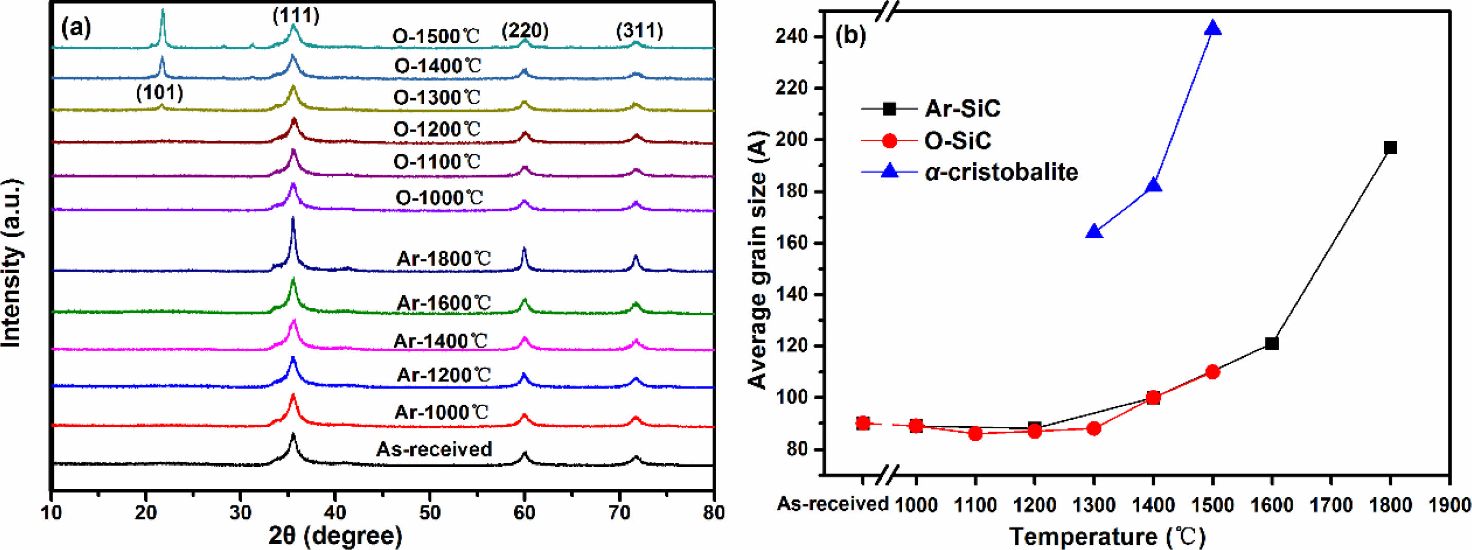
The XRD patterns of fibers before and after heat treatment are shown in Fig. 1a. The “Ar-” and “O-” in Fig. 1a represent fibers heat treatment in argon and oxidation atmosphere, respectively. It can be seen that all the fibers present three diffraction peaks around 35.5°, 59.8°, and 71.8°, which is well matched with (111), (220) and (311) diffraction planes of β-SiC, respectively [33]. When the temperature is elevated to 1300 °C in oxidation atmosphere, other peak that is indexed as (101) planes of the α-cristobalite phase also begin to appear [29]. Apparently, all the XRD diffraction peaks become sharper with the rising temperature, indicating that the crystallinity of fibers increase accordingly. The average grain size of β-SiC and α-cristobalite are respectively calculated from the half-value width of the (111) peak of β-SiC and (101) peak of α-cristobalite using the Scherrer's formula, and the calculation results are shown in Fig. 1b. The “Ar-SiC” and “O-SiC” in Fig. 1b represent the average grain size of β-SiC in fibers, after heat treatment in argon and oxidation atmosphere, respectively. The calculation results show that the Ar-SiC almost unchanged at the temperatures not exceeding 1200 °C. After that, Ar-SiC grow into larger crystals and the growth rate is found to increase with the rising heat treatment temperature. The O-SiC have a very similar trend to the Ar-SiC at temperatures from1000 °C to 1500 °C. That is to say, the grain size of SiC in fibers is not affected by heat treatment atmosphere, it is only sensitive to heat treatment temperature. For α-cristobalite, when the temperature is below 1300 °C, its XRD diffraction peak cannot be detected. This is because silica formed at low temperature is usually amorphous phase. The grains of α-cristobalite grow rapidly with the increasing heat treatment temperature, once they appear at 1300 °C.
Effect of heat treatment on interior microstructure of fibers
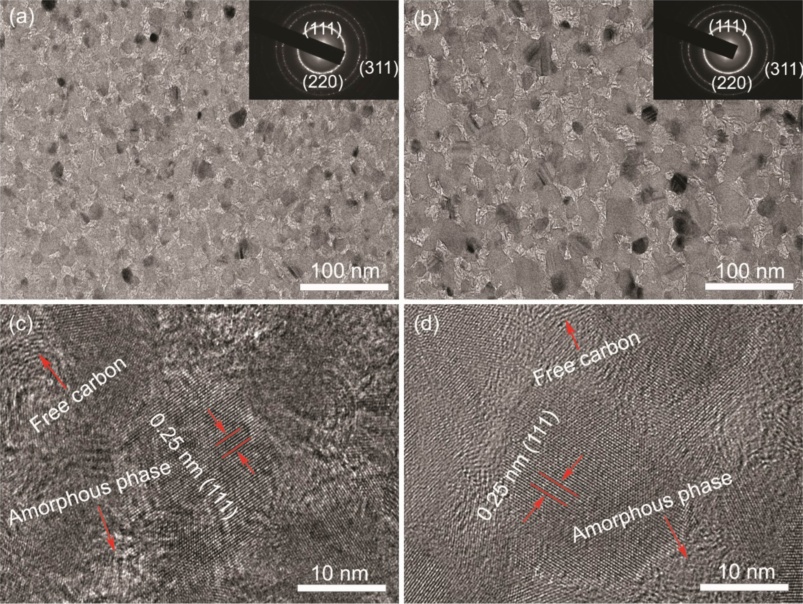
The high-resolution TEM (HRTEM) images and the corresponding selected area electron diffraction (SAED) patterns of fibers before and after heat treatment in argon atmosphere are shown in Fig. 2. It can be seen that the KD-II SiC fibers are composed of β-SiC grains, SiCxOy amorphous phase and free carbon. In addition, the size and distribution of SiC grains are uniform throughout the fiber. The gap of SiC grains is filled with a second phase which is composed of SiCxOy amorphous phase and free carbon. The Fig. 2(a) and Fig. 2(b) show that the apparent coalescence and growth of the SiC grains occurred after heat treatment at 1600 °C. The electron diffraction patterns of the bulk fiber (inset images) present three main rings, corresponding to the (111), (220), and (311) planes of the β-SiC phase from the inside to the outside [34]. Obviously, these results are well consistent with the XRD analysis, discussed earlier. By comparing the enlarged images Fig. 2(c) and Fig. 2(d), we found that the SiCxOy amorphous phase have a dense structure at the begining, and it becomes to a diffuse structure after heat treatment at 1600 °C. It means that the decomposition of SiCxOy amorphous phase occurred in fibers after heat treatment at 1600 °C. According to previous studies [35, 36], when fibers are heat treated at high temperature, SiCxOy amorphous phase will decompose into SiC nanoparticles and free C, as well as the gas of SiO and CO, the chemical reaction is shown in eqn (1).

It can be concluded that the decomposition of SiCxOy amorphous phase in fibers provides space and raw materials for SiC grain growth and degenerates the original structure of the fibers.
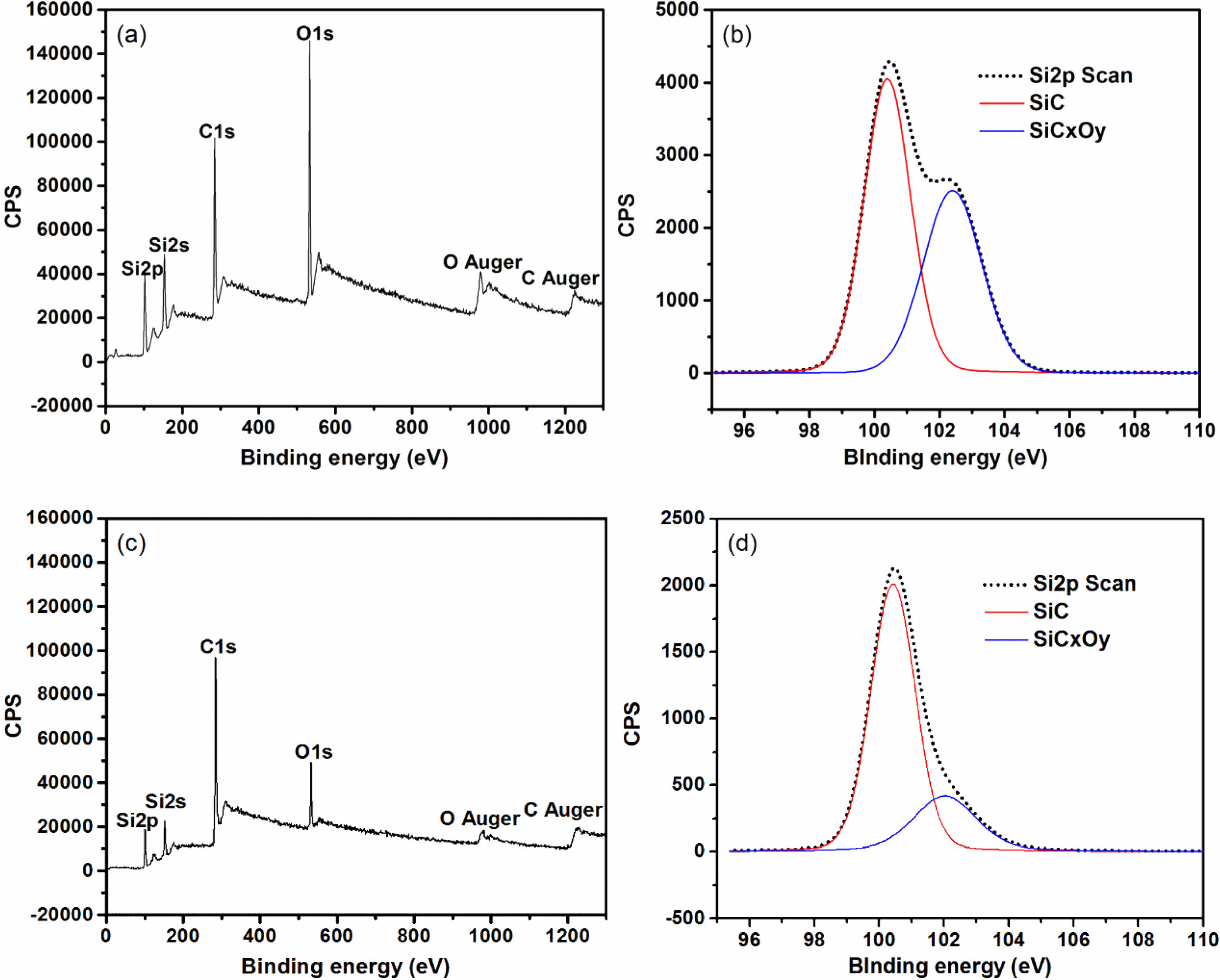
In order to further clarify the decomposition of SiCxOy amorphous phase in fibers after heat treatment at high temperature, XPS spectra analysis is carryed out. Survey XPS spectra recorded from the fibers powder is shown in Fig. 3(a) and Fig. 3(c), the intensity of the peaks O1s, Si2s and Si2p of the fibers after heat treatment in argon atmosphere at 1600 °C dramatically decreased compared with those as-received. It indicates that the content of silicon and oxygen in the fibers rapidly reduces after heat treatment at 1600 °C. This is due to the gas of SiO is released during the decomposition of SiCxOy amorphous phase. As show in Fig. 3(b) and Fig. 3(d), the Si2p spectrum can be fitted into a main peak which is assigned to silicon in the bulk SiC, and a shoulder peak which is originates from silicon in the SiCxOy amorphous phase [37]. It is obvious that the area percentage of shoulder peak in the Si2p spectrum decreases rapidly, form original 39% to 11%, indicating about 70% of SiCxOy amorphous phase have been decomposed after fibers heat treatment at 1600 °C.
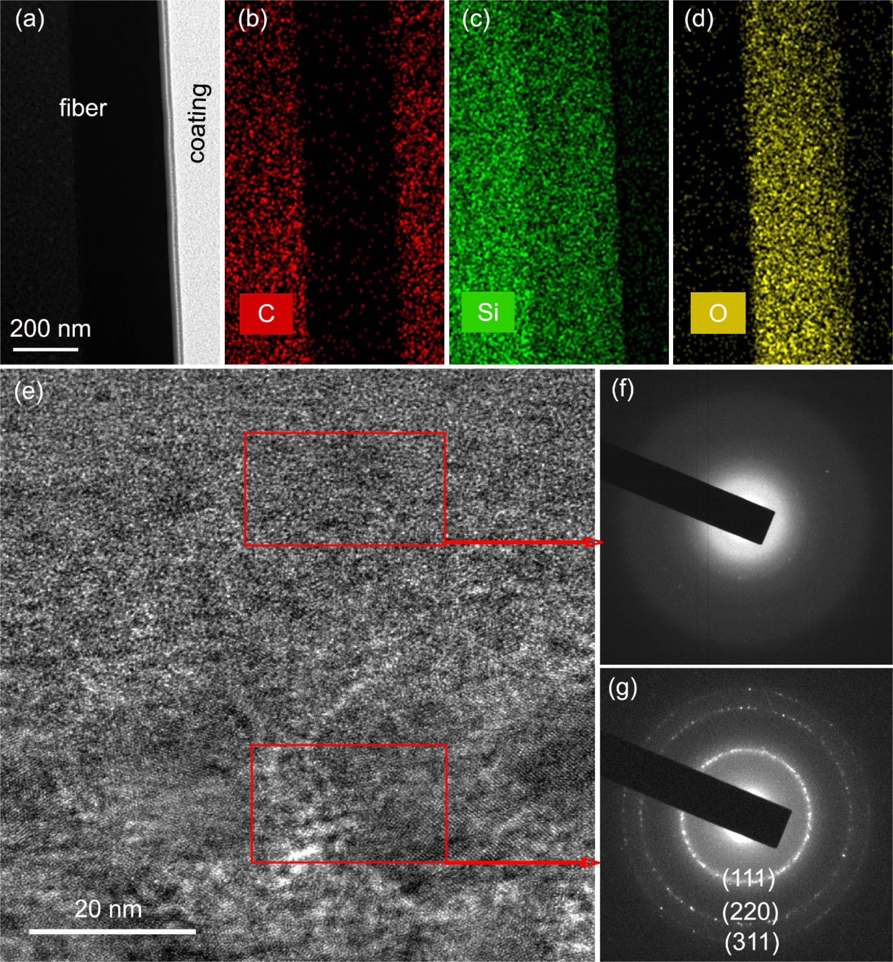
The SiC fibers after heat treatment in oxidation atmosphere at 1300°C were investigated by HAADF-STEM and HRTEM. Fig. 4(a-d) show the low-magnified HAADF-STEM micrograph and elemental distribution at the interface between oxide layer and internal fibers. It can be seen that the boundary of the interface is clearly visible and almost no oxygen element diffuses into the internal fibers. Fig. 4(e-g) show the HRTEM micrograph and corresponding selected-area electron diffraction pattern (SAED) of fibers at the interface. From Fig. 4(f), it can be seen that the SAED of oxide layer is blurry, indicating that most of the silica phase still has a poor crystallinity, although the XRD peak of α-cristobalite has already appeared after heat treatment at 1300 °C in oxidation atmosphere for 1 hour. By contrast, the SAED of internal fibers Fig. 4(g) clearly presente three diffraction rings corresponding to the (111), (220), and (311) planes of the β-SiC phase, and the HRTEM picture Fig. 4(e) show that the microstructure of internal fibers is as the same with those fibers heat treated in argon atmosphere. That is to say, the oxygen element is difficult to diffuse into the internal fibers and the oxidation reaction occurs only on the fiber surface during oxidation heat treatment [21].
Effect of heat treatment on surface morphologies of fibers
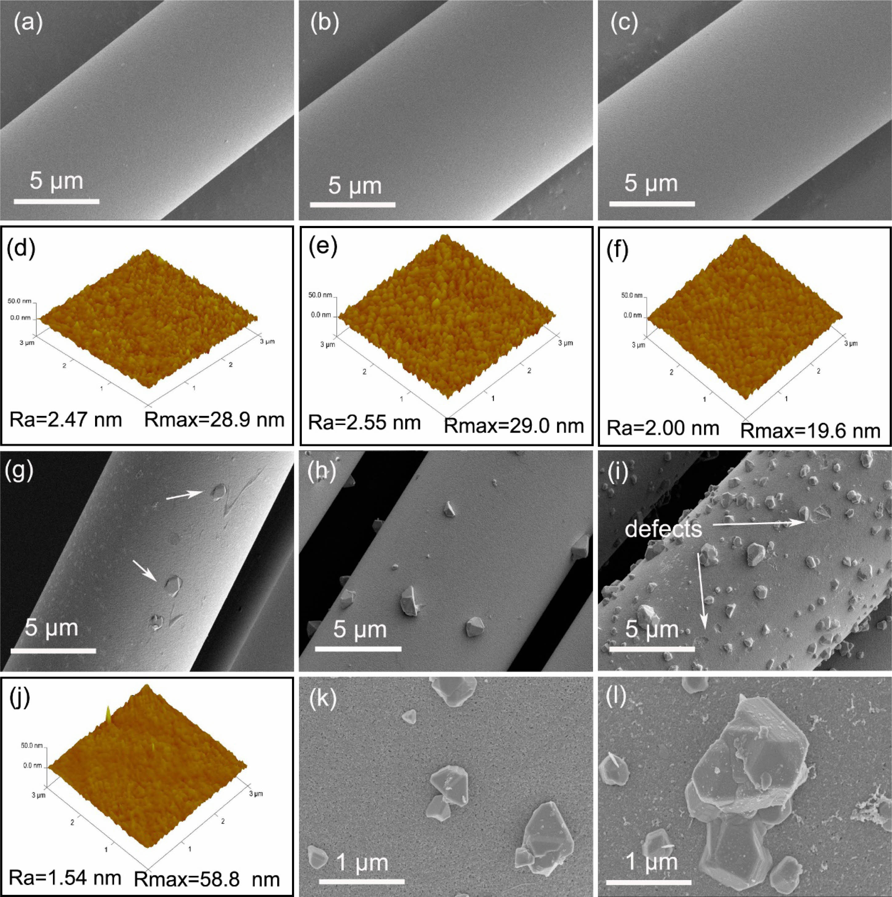
In order to fairly detect the varieties of fibers surface morphologies with the increasing temperature, a characterization method of SEM combined with AFM is used in this study. Fig. 5 shows the surface morphologies of the fibers before and after heat treatment in argon atmosphere. It can be seen from the SEM pictures Fig. 5(a-c) that the surface of fibers is very smooth and featureless, and almost have no change even the heat treatment temperature up to 1200 °C. Nevertheless, the subtle changes can be found from AFM images Fig. 5(d-f), which the value of Ra and Rmax begin to decrease when the heat treatment temperature reaching at 1200 °C. It means that the fibers surface becomes smoother after heat treatment. Smoother surface of the fiber is very important for obtaining good fibrous fracture behavior of ceramic matrix composites (CMCs) [38, 39]. However, when the temperature is increased to 1400 °C, particles which are identified as single crystal β-SiC form on fibers surface [36], as shown in Fig. 5(g). The corresponding AFM image Fig. 5(j) display that the value of Ra continues to decrease to 1.54 nm and the value of Rmax rapidly increased to 58.8 nm due to the formed β-SiC particles. With the further increasing of heat treatment temperature up to 1600 °C, both the number and size of β-SiC particles on fibers surface are increased, as shown in Fig. 5(h). During the decomposition of SiCxOy, the reaction product SiC nanoparticles deposite on the surface of the fiber and become nucleations of single crystal β-SiC particles. Furthermore, this single crystal β-SiC continues to grow by the SiO reacted with CO to form SiC, the gaseous reaction is shown in eqn (2).

With the growth of single crystal β-SiC particles, numerous microscopic pores appear on the fibers surface, as shown in the local enlarged drawing Fig. 5(k). These microscopic pores are caused by the SiO and CO gas which is released during the decomposition of SiCxOy amorphous phase. When the temperature reached at 1800 °C, large amounts of particles form on fibers surface, and these particles are easy to fall, as a consequence, some pits or possibly other defects are left on the fibers surface, as shown in Fig. 5(i) and its local enlarged drawing Fig. 5(l). This is different from the fibers that heat treatment in vacuum. Under vacuum atmosphere, the released SiO and CO gas is promptly extracted and will not to form β-SiC grains, resulting in smooth and defects-free fibers surface [35].
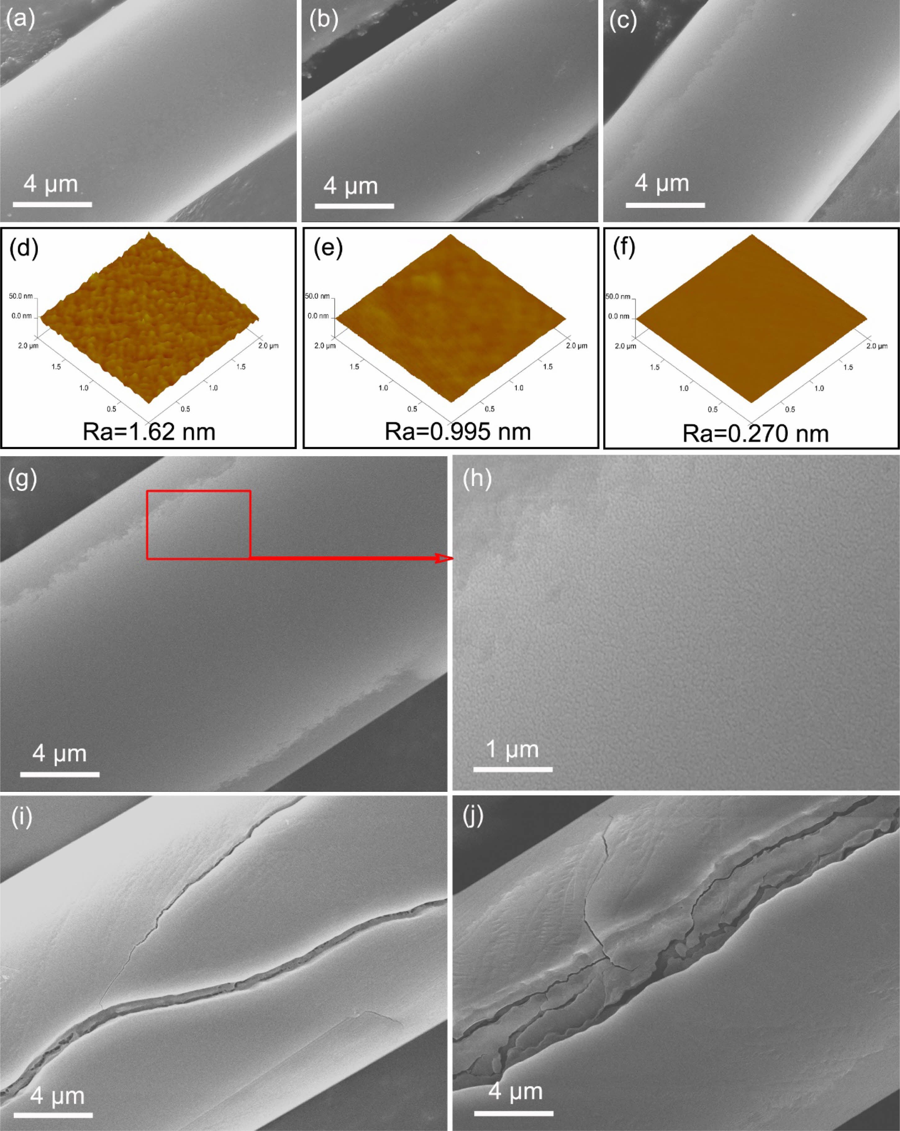
Fig. 6 shows the surface morphologies of fibers heat treatment in oxidation atmosphere from 1000 °C to 1500 °C. The SEM images Fig. 6(a-c) show that the surface morphologies of fibers after heat treatment in oxidation atmosphere at 1000 °C, 1100 °C and 1200 °C, are as same as those as-received fibers Fig. 5(a). Similarly, the fine structures of the fibers surface are investigated in detail using AFM, revealing that the value of Ra rapidly drops to 0.270 nm from original 2.47 nm (as show in Fig. 5(d)), when the heat treatment temperature just reaching at 1200 °C. Obviously, fibers heat treatment in oxidation atmosphere have a smoother surface than those heat treatment in argon atmosphere at the same temperature. That is to say, the amorphous silicon oxide layer formed on the fibers surface reduces their surface roughness. Although the fibers surface morphologies look like unchanged after heat treatment at 1300 °C (as show in Fig. 6(g)), many microcracks can be observed in the partial enlargement Fig. 6(h). With the increasing heat treatment temperature, the large cracks are formed on the fibers surface, and the higher temperature the heat treatment possess, the larger the cracks are, as shown in Fig. 5(i) and Fig. 5(j), the surface morphologies of fibers after heat treatment at 1400 °C and 1500 °C. According to previous studies [40, 41], at high temperatures and low cooling rates, thermal stress in amorphous silica oxide layer is relaxed by viscous flow, so most thermal stress is determined and no cracks form. But the thermal stress that develops in crystalline scales is partially relaxed by cracking during oxidation.
Effect of heat treatment on fracture morphologies of fibers
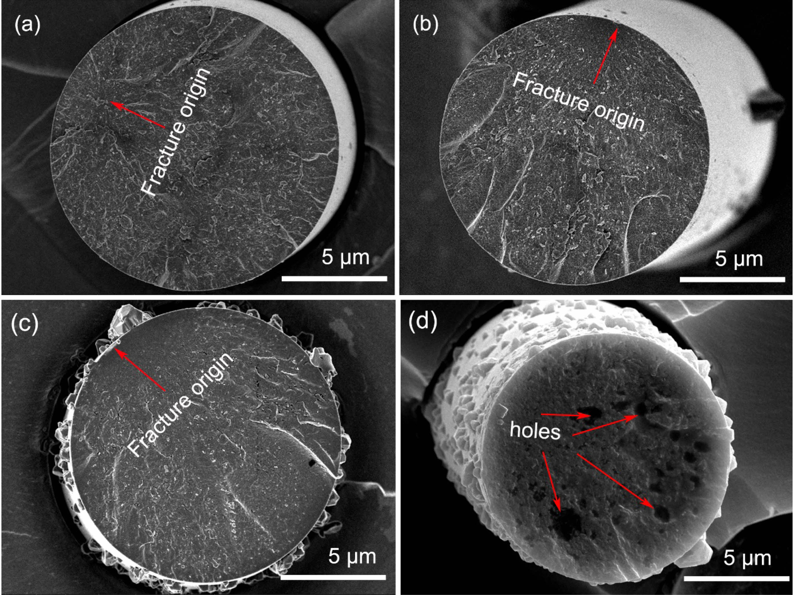
The fracture morphologies of the fibers before and after heat treatment in argon atmosphere are shown in Fig. 7. As can be seen from this Figure, the fracture surface is consisted of fracture source, surrounding mirror and hackle regions, which is typical brittle fractures [42]. For fibers heat treatment at the temperatures below 1200 °C, their fracture is initiated from internal flaws, including holes, inclusions and cracks, as shown in Fig. 7(a), these internal flaws are left behind during the production process of this fibers [43]. For the fibers after heat treatment at 1400 °C and 1600 °C, their fracture is originated from the surface defects, resulting by the β-SiC grains on the fibers surface, as shown in Fig. 7(b) and Fig. 7(c). From these observations, it is considered that the tensile strength is much more sensitive to larger surface defects, compared with the smaller internal flaws. Moreover, as can be seen from these fracture morphologies, the structure of fibers gradually became loose with the increasing heat treatment temperature. Especially, when the temperature reached 1800 °C, many big holes can be seen on the fracture surface, as shown in Fig. 7(d). As mentioned above, it is easy to conclude that the structure of fibers gradually deteriorated with the increasing temperature [44].
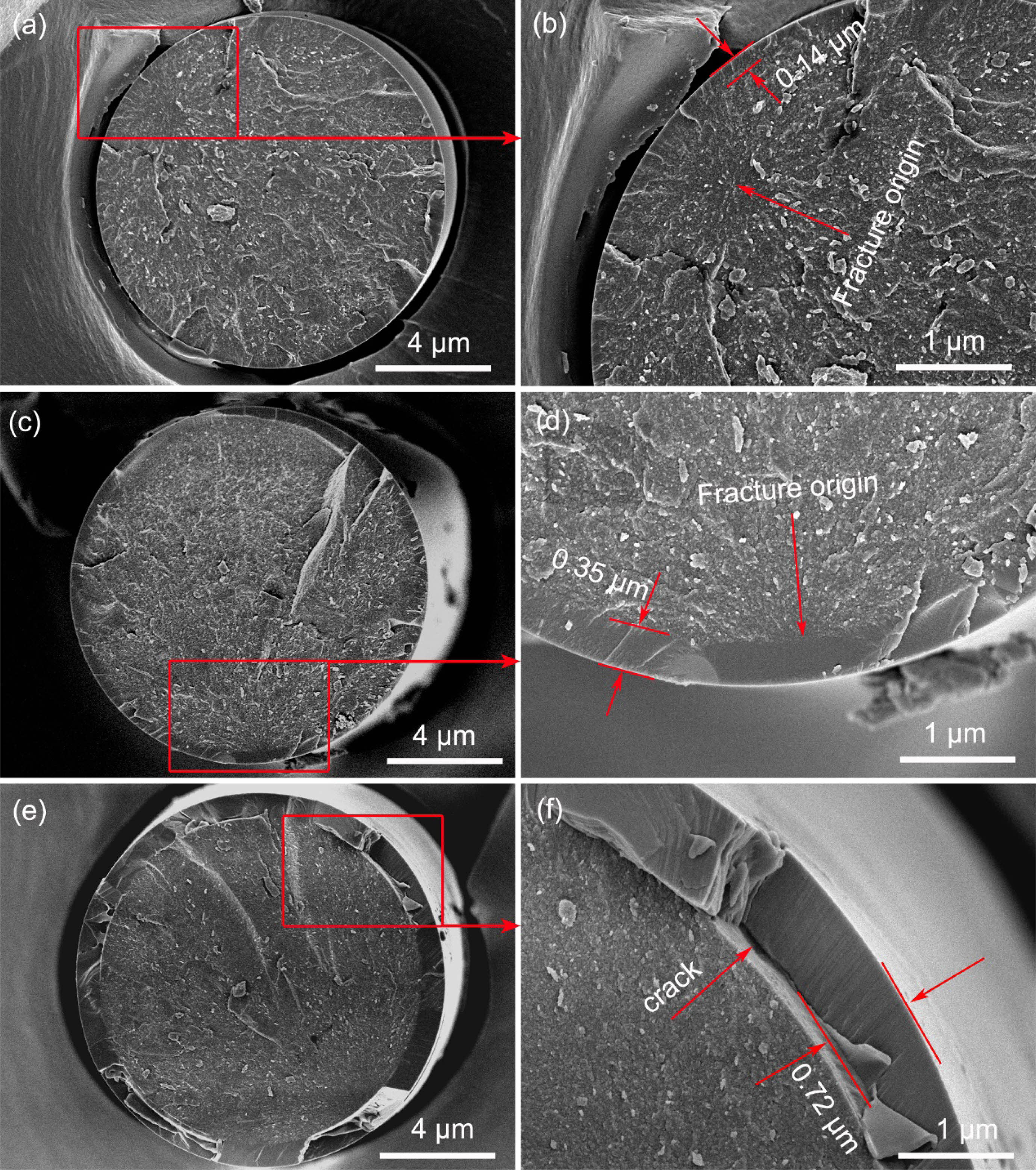
The fracture morphologies of the fibers heat treatment in oxidation atmosphere are shown in Fig. 8. It can be seen from the Fig. 8(a) and its local enlarged Fig. 8(b) that an oxide layer (about 0.14 μm) form on fibers surface after heat treatment at 1100 °C. The whole fracture surface is flat, the oxide layer and internal fibers are almost on the same plane. The fracture origins are internal flaws as the same as those fibers heat treatment in argon atmosphere. These results suggested that the oxide layer had little effect on the fracture morphologies of the fibers at a relatively low temperature [21]. With the increasing of heat treatment temperature, the thickness of oxide layer gradually increases and the flatness of fracture surface is getting worse, as shown in Fig. 8(c) and Fig. 8(d). Besides, it can be found that the fracture is initiated from the interface between oxide layer and internal fibers, after heat treatment at 1300 °C. This can be attributed to the big residual stress at the interface. Randall S. Hay et al. [45, 46] systematically studied the oxidation mechanism of SiC fibers, they believed that there are three sources of residual stress. Firstly, the growth stress, it is caused by a very large volumetric change (~220%) during the oxidation of SiC to SiO2. Secondly, the thermal stress, it is induced by thermal expansion mismatch of oxide layer and internal fiber. Thirdly, the phase transformation stress, it is the result of the amorphous silica transform into crystalline α-cristobalite. When the temperature up to 1500 °C, the oxide layer has reached 0.72 μm and spalling of it has occurred, due to the excessive oxidation, as shown in Fig. 8(e) and Fig. 8(f). The oxidation rate of fibers is well consistent with the Deal-Grove model [47, 48]. This model predicts thickness of oxide layer of 120 nm, 400 nm and 750 nm would form in 1 hour in dry air at 1100 °C, 1300 °C and 1500 °C, respectively [49].
Effect of heat treatment on tensile strength of fibres
As we all known, SiC fibers are brittle material, and their strength greatly depends on the amount of defects in the fibers. In the case of a random distribution of defects, the strength of the fibers is also polydisperse. According to the Guerra Faith brittle fracture theory and the Webster weakest link principle [50], the Weibull model is appropriate to analyse and evaluate the tensile strength of SiC fibers [51]. In this model, the cumulative probability of fracture P(σ) is the percentage of broken fibers among the tested fibers when the tensile stress is equal to or less than σ.

By taking the natural logarithm of Eq. (3) and rearranging the relationship, we obtain Eq. (4):

And the tensile strength can be corrected by

Where the Γ is Gamma function.
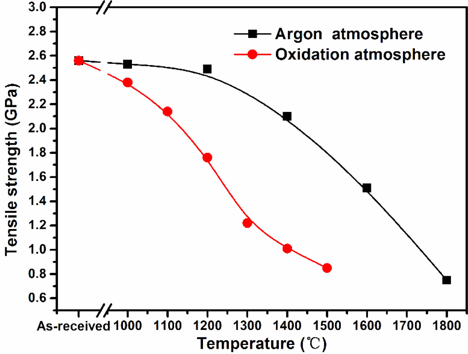
In this study, 50 monofilament fibers of each set of samples were measured. After handling according to the method mentioned above, we obtained the tensile strength of each group of fiber samples. The variations of tensile strength with rising heat treatment temperature of fibers heat treatment in argon atmosphere and oxidation atmosphere are shown in Fig. 9. It is evident that the tensile strength of fibers heat treatment in argon atmosphere decreased very slowly when the temperature below 1200 °C. At this temperature, the microstructure of the fibers almost do not change except for the reduction of surface roughness. However, after heat treatment temperature up to 1400 °C, the tensile strengh decreased to 1.20 GPa, 82% of their original strength. The tensile strength degeneration is caused by the appearance of surface defects and growth of β-SiC grains at this temperature. An earlier work by Zhao C and Wang Y [52] also supports the assertion that core flaw initiation means a relatively high tensile strength whereas a surface flaw initiation is always related to low strength. Subsequently, the tensile strength of fibers rapidly decreased due to the structure gradually deteriorated with the increasing of heat treatment temperature, and finally dropped to 0.75 GPa at 1800 °C. In combination with the previous analysis, it is easy to conclude that tensile strength degeneration of fibers heat treatment in argon atmosphere can be attributed to the appearance of surface defects, growth of β-SiC grains and the decomposition of amorphous phase. Therefore, the method that can suppress the decomposition of SiCxOy amorphous phase may mitigate the sharp tensile strength degradation. In contrast, the tensile strength of fibers which heat treatment in oxidation atmosphere present a different variation compared with those heat treatment in argon atmosphere. Their tensile strength decreasing started at 1000 °C, and intensely dropped to 1.16 GPa at 1300 °C. This is due to the existence of residual stress at the interface between oxide layer and internal fibers. Especially, the appearance of microcracks due to the thermal stress result in the further reduction of fibers tensile strength, when the fibers are heat treatment at above 1300 °C. In addition, from the previous XRD results, the growth of β-SiC grains is also occurred as the same with those fibers heat treatment in argon atmosphere. As stated above, it can be concluded that the interfacial residual stress, surface cracks and growth of β-SiC grains can degrade the fibers tensile strength after exposure at high temperatures in oxidation atmosphere.
In the further, a feasible approach to maintain fiber strength to high-temperature in argon atmosphere is fabricating nearly stoichiometric polycrystalline SiC fibers. This approach fundamentally solves the problem of high-temperature thermal decomposition of KD-II SiC fibers by removing SiCxOy amorphous phase. The approach to maintain fiber strength to high-temperature in oxidation atmosphere is surface coating or fabricated to SiCf/SiC composites. On the one hand, the surface coating can hinder the thermal decomposition of SiCxOy amorphous phase. On the other hand, the the thermal stress between surface layer and SiC fibers is small due to their similar thermal expansion coefficients.
|
Fig. 1 (a) XRD patterns and (b) average grain size of β-SiC and α-cristobalite of KD-II SiC fibres before and after heat treatment |
|
Fig. 2 HRTEM images and the corresponding SAED patterns (inset) of KD-II SiC fibers: (a) and (c) as-received; (b) and (d) heat treatment in argon atmosphere at 1600 °C. |
|
Fig. 3 Survey XPS spectra and the Si2p spectrum of fibers: (a) and (b) as-received; (c) and (d) heat treatment in argon atmosphere at 1600 °C. |
|
Fig. 4 (a-d) element area scanning and (e-g) HRTEM image and the corresponding SAED patterns of fibers heat treatment in oxidation atmosphere at 1300 °C. |
|
Fig. 5 Surface morphologies of fibers heat treatment in argon atmosphere at different temperatures. (a) and (d) as-received; (b) and (e) 1000 °C; (c) and (f) 1200 °C; (g) and (j) 1400 °C; (h) and (k) 1600 °C; (i) and (l) 1800 °C. |
|
Fig. 6 Surface morphologies of fibers heat treatment in oxidation atmosphere at different temperatures: (a) and (d) 1000 °C; (b) and (e) 1100 °C; (c) and (f) 1200 °C; (g) and (h) 1300 °C; (i) 1400 °C; (j) 1500 °C. |
|
Fig. 7 Fracture morphologies of fibers heat treatment in argon atmosphere at different temperatures: (a) as-received; (b) 1400 °C; (c) 1600 °C; (d) 1800 °C. |
|
Fig. 8 Fracture morphologies of fibers heat treatment in oxidation atmosphere at different temperatures: (a) and (b) 1100 °C; (c) and (d) 1300 °C; (e) and (f) 1500 °C. |
|
Fig. 9 Evolution of tensile strength of fibers heat treatment in argon and oxidation atmosphere. |
In this study, KD-II SiC fibers were heat treated in argon and oxidation atmosphere at different temperatures, respectively. The effects of heat treatment on microstructure evolution and the related strength degradation of fibers are comprehensively investigated. The results show that fibers heat treatment in argon atmosphere can maintain their microstructure and tensile strength up to 1200 °C. However, a sharp tensile strength degradation of fibers is occurred when the heat treatment temperature reached 1400 °C, because their fracture origin turns to surface defects from internal flaws. With the increasing of heat treatment temperature, the structure of fibers is gradually destroyed, accompanied by the decomposition of SiCxOy amorphous phase and the growth of β-SiC grains. When the temperature reached at 1800°C, the tensile strength decreased to 0.75 GPa, only 29% of original strength. Comparing with those fibers heat treatment in argon atmosphere, the fibers heat treatment in oxidation atmosphere at the same temperatures have lower tensile strength. This is due to the increase of the interfacial residual stress which developed as a result of the mismatch in thermal expansion coefficients between oxide layer and internal fibers and the phase transformation from amorphous silica to α-cristobalite. Besides, cracks which caused by the thermal stress appeare on the fibers surface after oxidation temperature exceed 1300 °C, resulting in further reduction of tensile strength. At last, the tensile strength is found to be only 0.79 GPa, after oxidation at 1500 °C.
Funding: This work was financially supported by the National Basic Research Program of China (ZB 4142 XXXXX) and the State Key Laboratory for Powder Metallurgy Foundation (2020), Central South University, Changsha, China.
- 1. Y. Zayachuk, P. Karamched, C. Deck, et al. Acta Materialia 168 (2019) 178-189.
-

- 2. A. Ortona, A. Donato, G. Filacchioni, et al. Fusion Engineering and Design 51 (2000) 159-163.
-
- 3. C.A. Nannetti, B. Riccardi, A. Ortona, et al. Journal of Nuclear Materials 3 (2002) 1196-1199.
-
- 4. A. Kohyama, Ceramics Japan 39[3] (2004) 171.
- 5. W. Guo and Y. Gao, Journal of Ceramic Processing Research 24[2] (2023) 378-389.
-
- 6. S. Zhao, X. Zhou, J. Yu, et al. Fusion Engineering & Design 88[9-10] (2013) 2453-2456.
-
- 7. S. Zhao, Z. Yang, X. Zhou, Journal of the American Ceramic Society 98 (2015) 1332-1337.
-
- 8. M. Chen, H. Qiu, J. Jiao, et al. Advanced Materials Research 1058 (2014) 170-175.
-
- 9. K.W. Nama, C.K. Moon, J.W. Kim, Journal of Ceramic Processing Research 14[4] (2013) 441-444.
-
- 10. Alfian Noviyanto, D.-H. Yoon, Journal of Ceramic Processing Research 13[4] (2012) 392-397.
-
- 11. J.Y. Park, S.M. Kang, W.-J. Kim, Journal of Ceramic Processing Research 10[3] (2009) 364-366.
-
- 12. A.R. Bunsell, A. Piant Journal of Materials Science 41[3] (2006) 823-839.
-
- 13. D. Zhao, H. Wang, X. Li, Wuji Cailiao Xuebao 24[6] (2009) 1097-1104.
-
- 14. K.W. Nama, C.K. Moon, I.S. Seo, Journal of Ceramic Processing Research 12[6] (2011) 646-649.
-
- 15. G.-Y. Gil, D.-H. Yoon, Journal of Ceramic Processing Research 12[4] (2011) 371-375.
-
- 16. J.Y. Park, H.S. Hwang, W.J. Kim, et al. Journal of Nuclear Materials 307[2] (2002) 1227-1231.
-
- 17. M. Chen, H. Qiu, J. Jiao, et al. Key Engineering Materials 544 (2013) 43-47.
-
- 18. Y.J. Jooa, K.Y. Cho, C.J. Kim, Journal of Ceramic Processing Research 20[5] (2019) 563-569.
-
- 19. I. Spitsberg, J. Steibel, International Journal of Applied Ceramic Technology 1[4] (2010) 291-301.
-
- 20. Y. Katoh, L.L. Snead, C.H. Henager, et al. Journal of Nuclear Materials 455[1-3] (2014) 387-397.
-
- 21. R.S. Hay, Journal of the American Ceramic Society 101[2] (2018) 831-844.
-
- 22. J. Wang, L. Zhang, Q. Zeng, et al. Journal of the American Ceramic Society 91[5] (2010) 1665-1673.
-
- 23. J.J. Sha, T. Hinoki, A. Kohyama, Corrosion Science 50[11] (2008) 3132-3138.
-
- 24. J.J. Sha, T. Nozawa, J. Park, et al. Journal of Nuclear Materials 329[1] (2004) 592-596.
-
- 25. G. Kister, B. Harris, Composites Part A 33[3] (2002) 435-438.
-
- 26. J.J. Sha, T. Hinoki, A. Kohyama, Materials Characterization 60[8] (2009) 796-802.
-
- 27. T. Shimoo, K. Okamura, M. Ito, et al. Journal of Materials Science 35[15] (2000) 3733-3739.
-
- 28. S. Cao, J. Wang, H. Wang, Materials Science and Engineering: A 673 (2016) 55-62.
-
- 29. L. Li, K. Jian, Y. Wang, Key Engineering Materials 726 (2017) 132-136.
-
- 30. BS ISO 11566:1996 Method B: Carbon fiber: Determination of the Tensile Properties of as Single-filament Specimens.
-
- 31. ASTM D-3379-75, in Annual Book of ASTM Standards. American Society for Testing and Materials, Philadelphia, 1985, Part 15.
- 32. H. Liu, H. Cheng, J. Wang, et al. Materials Science & Engineering A 525[1-2] (2009) 121-127.
-
- 33. E.J. Jung, Y.J. Lee, S.R. Kim, et al. Journal of Ceramic Processing Research 15[6] (2014) 447-450.
-
- 34. Y. Chai, X. Zhou, H. Zhang, Ceramics International 43[13] (2017) 9934-9940.
-
- 35. T. Shimoo, K. Okamura, I. Tsukada, et al. Journal of Materials Science 34[22] (1999) 5623-5631.
-
- 36. S. Cao, J. Wang, H. Wang, CrystEngComm 18[20] (2016) 3674-3682.
-
- 37. L. Porte, A. Sartre, Journal of Materials Science 24[1] (1989) 271-275.
-
- 38. C. Sauder, A. Brusson, J. Lamon, International Journal of Applied Ceramic Technology 7[3] (2010) 291-303.
-
- 39. R. Usukawa, T. Ishikawa, Ceramics 1 (2018) 165-174.
-
- 40. R.S. Hay, M. Pavel, Journal of the American Ceramic Society 102 (2019) 397-415.
-
- 41. R.S. Hay, S.J. Robertson, Ruggles-Wrenn, M.B. et al. Journal of the American Ceramic Society 104[7] (2021) 3562-3592.
-
- 42. G.E. Youngblood, C. Lewinsohn, R.H. Jones, et al. Journal of Nuclear Materials 289[1-2] (1985) 1-9.
-
- 43. Hiroshi, Oda, Toshihiro, Ishikawa, International Journal of Applied Ceramic Technology 14[6] (2017) 1031-1040.
-
- 44. Y. Qin, Y. Li, Y. Song, Ceramics International 43[12] (2017) 9128-9132.
-
- 45. Y. Zhao, Y. Chen, S. Ai, et al. International Journal of Plasticity 118 (2019) 173-189.
-
- 46. T.. Shimoo, T. Hayatsu, M. Takeda, et al. Journal of the Ceramic Society of Japan 102[1187] (2010) 617-622.
-
- 47. B.E. Deal, A.S. Grove, Journal of Applied Physics 36 (1965) 3770-3778.
-
- 48. V. Presser, K.G. Nickel, Critical Reviews in Solid State and Materials Sciences 33 (2008) 1-99.
-
- 49. R.S. Hay, R.J. Chater, Journal of the American Ceramic Society 100[9] (2017) 4110-4130.
-
- 50. A.A. Griffith, Philosophical Transactions of The Royal Society A Mathematical Physical and Engineering Sciences A221[4] (1920) 163-198.
-
- 51. H.F. Wu, A.N. Netrwavali, Journal of Materials Science 27[12] (1992) 3318-3324.
-
- 52. C. Zhao, Y. Wang, G. Zhang, et al. Journal of Materials Science & Technology 33[11] (2017).
-
 This Article
-
2023; 24(4): 742-752
Published on Aug 31, 2023
- 10.36410/jcpr.2023.24.4.742
- Received on Jul 14, 2023
- Revised on Jul 30, 2023
- Accepted on Aug 2, 2023
Services
- Abstract
introduction
experimental procedure
results and discussion
conclusions
- Acknowledgements
- References
- Full Text PDF
Shared
Correspondence to
- Guangmin Hu
-
State Key Laboratory for Powder Metallurgy, Central South University, Changsha 410083, P.R. China
Tel : +86 18821273068 - E-mail: huguangmin@sjtu.edu.cn
Clean-Energy Research Institute(CRI), Hanyang University, 222, Wangsimni-ro, Seongdong-gu, Seoul, 04763, Korea
E-mail: jcpr@hanyang.ac.kr