


- Experimental analysis of treated waste foundry and waste ceramics sand by replacement of fine aggregate in concrete
K.V. Boobala Krishnana,*, K. Nirmalkumarb, V. Sampathkumarb and P.C. Muruganc
aDepartment of Civil Engineering, Dr.N.G.P Institute of Technology, Coimbatore – 641048
bDepartment of Civil Engineering, Kongu Engineering College, Perundurai, Erode – 638060
cDepartment of Automobile Engineering, Kongu Engineering College, Perundurai, Erode – 638060This article is an open access article distributed under the terms of the Creative Commons Attribution Non-Commercial License (http://creativecommons.org/licenses/by-nc/4.0) which permits unrestricted non-commercial use, distribution, and reproduction in any medium, provided the original work is properly cited.
Due to rapid urbanization and industrialization, excessive exploitation of natural resources like river sand and gravels is a major concern. This study investigated the use of waste foundry sand and waste ceramics as partial replacements for M-sand in concrete. M25 grade concrete with a 1:1.1:2.2 ratio and a water-to-cement ratio of 0.45 was used. Waste foundry sand underwent pre-treatment with sodium silicate to improve its applicability. Treated waste foundry sand (TWFCS) and 10% powdered waste ceramics were combined to partially replace M-sand in different proportions (0%, 10%, 15%, and 20%). Mechanical tests, including compressive, tensile, and flexural strength assessments, were conducted after 7, 14, and 28 days of curing. The concrete samples were exposed to a marine and acidic environment for 60 days. TWFCS 3 exhibited the lowest compressive strength (26.39 N/mm2) after exposure to an alkaline environment, while TWFCS 1 showed the highest compressive strength (28.63 N/mm2). Treated foundry sand showed superior mechanical properties, surpassing M-sand by 15% in terms of compressive, split tensile, and flexural strength. SEM and XRD analysis were used to evaluate the concrete containing treated waste foundry and ceramics sand.
Keywords: Treated waste foundry sand, Waste ceramics sand, Characteristics analysis, SEM analysis and XRD analysis
Concrete is the building material that is used the most in construction. Due to the development of infrastructure, the demand for concrete has increased rapidly over several decades [1]. Concrete was made of a variety of ingredients and water, including cement, fine aggregate, and coarse aggregate. Yet, due the consumption of sand, there emerges an expansion in the interest for fine total because of which the creation of coarse total and fine total arrived at around 40 billion tones [2]. Utilizing industrial wastes like fly ash, rice husk, bottom slag, ash, and foundry sand, which can significantly improve the efficiency of energy and the overall performance of the environment, has been the subject of numerous studies to meet the demand [3]. The use of these industrial wastes not only makes the concrete cheap, but it also helps solve problems with disposal in an efficient way. In any case, the modern squanders which are to be used for the substitution of fine total are handled to the essential particulars that presumably would coordinate with the properties of fine total [4]. The chemical and physical properties of the silicate sand produced by casting ferrous and non-ferrous metal are uniform. The Waste Foundry Sand is said to have a silica content that is comparable to that of regular sand [5, 6]. Be that as it may, the properties of Waste Foundry Sand totally rely upon the cycle engaged with projecting and the business' temperament [7]. It was seen that as almost 85%-90% of its particles to be more modest than 100 µm which demonstrates that the molecule size is like that of the fine total utilized in concrete [8]. Then, the sand that was thrown away can be used in the recycling process. Numerous researchers have demonstrated that the non-ferrous metal casting industry's discarded foundry sand can be directly used in concrete as a partial replacement for fine aggregate [9], whereas the ferrous metal casting industry's discarded foundry sand cannot be directly used in concrete due to its higher iron content. The iron substance in the foundry sand influences the strength and the limiting properties of the substantial [10]. Nonetheless, this foundry sand can be utilized in the substantial subsequent to eliminating the iron substance by appropriate treatment. Also, there are a lot of waste ceramic tiles in India, and between 30 and 40 percent of the production from manufacturing units ends up in landfills [11]. This study refers to a few journals, such as [12], which used foundry sand to partially replace fine aggregate in order to make concrete sustainable. By weight of fine aggregate, the percentages used to replace foundry sand were 10%, 20%, 30%, 40%, and 50%. It was then tried for its compressive strength of cement with M25 blend extent and at various relieving periods like 7 days, 14 days and 28 days. The findings demonstrated that foundry sand replaced 30 percent of the fine aggregate to achieve maximum strength. This was because concrete has less and less pores. Utilizing Waste Ceramic material as a partial substitute for fine aggregate [13], carried out an experimental investigation of the concrete. For fine aggregate, partial replacements were performed in various percentages of 0%, 5%, 10%, 15%, and 20%. For M30 grade concrete, the mix design was calculated. The findings demonstrated that the use of fine aggregate to replace 10% of Waste Ceramics yielded favorable results in both fresh and hardened concrete tests.
The following are the study's goals:
• To investigate Treated Waste Foundry and 10% Ceramic Sand (TWFCS) by partially replacing the fine aggregate with a percentage ranging from zero to twenty percent.
• To actually take a look at the mechanical strength and properties of the substantial blocks.
• To examine the Treated Waste Foundry and Ceramics Sand in the wake of presenting to different climate like corrosive, soluble and marine assault for 20 days, 40 days and 60 days separately.
• SEM and XRD analyses have been performed to verify the cast TWFCS concrete's structural information.
The materials which were employed in this project are as follows:
• Cement
• M-sand
• Coarse aggregate
• Waste Foundry sand
• Waste Ceramic sand
• Water
Cement
The concrete mix was made with Portland Pozzolona cement. The international cement standards required tests were carried out successfully [14]. According to the test results, the initial setting time was 29 minutes, and the final setting time was 10 hours.
M-Sand
In this review, M-Sand is utilized as a substitute of waterway sand in fine totals. Typically, the aggregates of hard granite stone are crushed to make this sand. The fine aggregate was found to be cubic in shape, washed, and graded I in accordance with IS 383-1970, with grounded edges. The M-sand was gathered by isolating it with strainers of 4.75 mm. To ensure a dust-free environment, this method ensured that the fine aggregate used in concrete did not contain any foreign particles or larger particles [15].
Coarse Aggregate
The Coarse aggregate used in this research was between 10 mm and 20 mm in size. They were tested with accordance to the IS 383-1970 standards. These aggregates were cleaned to remove the dirt using water and then dried completely for the usage. The Specific gravity of the coarse aggregate used was found to be 2.8 and the water absorption was found to be 1% [16].
Treated Waste Foundry Sand (TWFS)
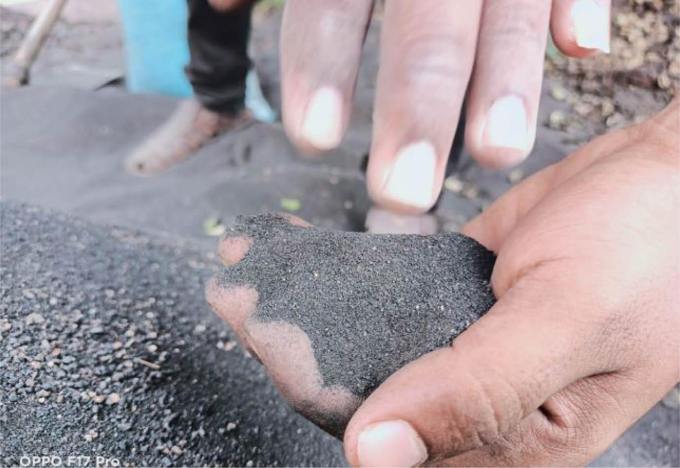
Waste Foundry Sand is usually clean, high quality silica sand which is of uniform size used in the foundry casting process shown in Fig. 1. Foundry waste was gathered at coordinates Latitude: 11° 0' 34.2254" N and Longitude: 77° 72' 74.5790" E. The Waste Foundry Sand is treated with the sodium silicate solution in order to reduce the porosity in concrete significantly [17]. By treating it with the sodium silicate, there occurs a chemical reaction with the excess calcium in the concrete that binds the silicates permanently, thereby, making the surface more water repellent and wearable [18]. In order to consolidate the silica based aggregates in basic medium, an irreversible gel called acidified sodium silicate is used. There are two basic types of foundry sand i.e Green Sand and Silica sand [19]. The binder material in Green sand is bentonite clay which contains 85%-95% of silica content whereas the binder material in silica sand is core oil which contains 93%-99% of silica content. Since, Silica Foundry Sand has the properties close to that of natural sand, this is used as a replacement material for sand in concrete [20]. In this research, Silica Waste Foundry sand is partially replaced with the fine aggregates in various percentages such as 0% (CC), 10% (TWFS 1), 15% (TWFS 2) and 20% (TWFS 3).
Waste Ceramic Sand
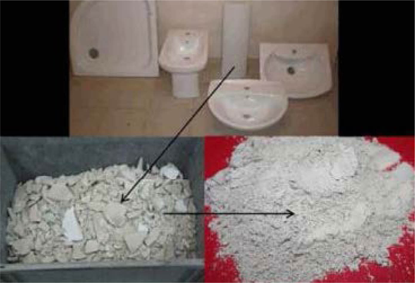
Waste Ceramic tile materials are usually hard and can have considerable value of specific gravity [21]. Ceramic waste was gathered at coordinates Latitude: 11° 0' 37.4508" N and Longitude: 76° 56' 59.6508" E. The usage of the granulated or powdered form of ceramic tiles is not only cost effective but also adds considerable strength to the concrete shown in Fig. 2. In this research, the waste ceramic tiles were broken in to pieces and a jaw crushed is used to crush down the pieces to get 4.75 mm size (Pradeep et al., 2016). It is then used along with the Treated Waste Foundry Sand having a constant percentage of 10% by its total weight [22].
Water
Water actually takes part in the chemical reaction that cement and water have, making it one of the most crucial components of concrete. Water's quality and quantity should be carefully checked because it helps cement start a chemical reaction and gives it strength. Because it is frequently overlooked, the water's purity should be checked [23].
|
Fig. 1 Treated Waste Foundry Sand. |
|
Fig. 2 Waste Ceramic Sand. |
Cement used for the study was tested for parameters such as consistency, initial setting time and final setting time. Fine aggregate and Treated Waste Foundry Sand (TWFS) was tested for the sieve analysis and its specific gravity [24]. Coarse aggregates used in the concrete is tested for gradation, specific gravity and water absorption as per IS codes [25]. The foundry sand undergoes a pretreatment process by using sodium silicate. The Waste ceramics was tested for the sieve analysis and its specific gravity and mixed with the Treated Waste Foundry Sand of about 10% [26] by its total weight. In the TWFCS 1 mix, only 10% of Treated Waste Foundry and Ceramic Sand and 90% fine aggregates were used. The remaining ingredients were same as in CC mix. In the TWFCS 2 mix, only 15% of TWFCS and 85% fine aggregates were used. The remaining ingredients were same as in CC mix [27]. In the TWFCS 3 mix, only 20% of Treated Waste Foundry and Ceramic Sand and 80% fine aggregates were used. The remaining ingredients were same as in CC mix. Fresh concrete was tested for its workability by slump cone test. The hardened concrete specimens are subjected to the tests such as compression strength, split tensile strength test and flexural strength test at different stages of curing [28]. The hardened concrete of mix design M25 with its ratio 1:1.1:2.2 is also tested for its durability by exposing it to acidic, alkaline and marine environment for 60 days. It was also tested by using non-destructive methods such as SEM analysis and XRD analysis [29].
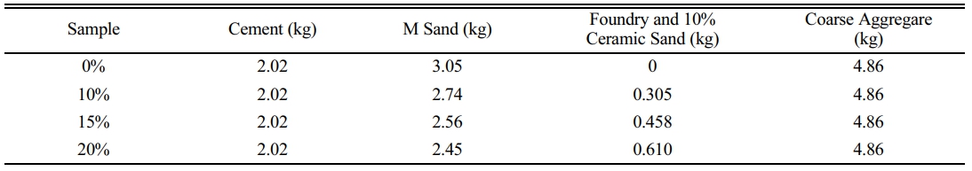
The code IS states: 10262-1979, the mix design is used and the quantity of materials is calculated [30]. For TWFCS concrete, the mix ratio is 1: 1.10: 2.20, with a water-to-cement ratio of 0.45 and a concrete grade of M25. The quantity of cube material is shown in Table 1.
The practice of dumping foundry sand in landfills is becoming less appealing as a result of the rising cost of disposal. In addition, as environmental concerns grow, the government has imposed stringent guidelines on how to dispose of industrial waste in the environment. This makes industries accountable for how they manage their waste. As a result, reusing and recycling waste became the effective solution to these issues [31]. Foundry sand and waste ceramics have numerous potential applications in the construction industry and projects, including the production of pavement block, mortar and brick block, asphalt concrete, a hydraulic barrier in the production of cement, filling highway embankments, stabilizing soil and reinforcement, and so on [32]. Traditional materials are saved, money is saved, and the impact on the environment is reduced by using these wastes. Nonetheless, the Foundry Sand was at first treated with synthetic substances in order to stay away from the contribution of responsive natural compound during the projecting phase of the substantial [33]. Additionally, the Treated Waste Foundry Sand concrete was found to have enduring qualities of unfavorable impacts of climate from the demonstrated outcomes from filtering boundaries like pH, the sort of material and the projecting of the substantial example [34]. The excavation pit is sometimes filled with ceramic waste on-site [35].
Numerous studies have found promising results when examining the mechanical behavior of Foundry and Ceramic Sand as a partial or complete replacement for fine aggregate in concrete. The Treated Waste Foundry and Ceramic Sand concrete's compressive strength, split tensile strength, flexural strength, acid attack test, alkaline test, chloride attack test, SEM analysis, and XRD analysis were examined in relation to the standard mix of the concrete in the study at various proportions of fine aggregate and replacement level of foundry sand.
Compressive strength
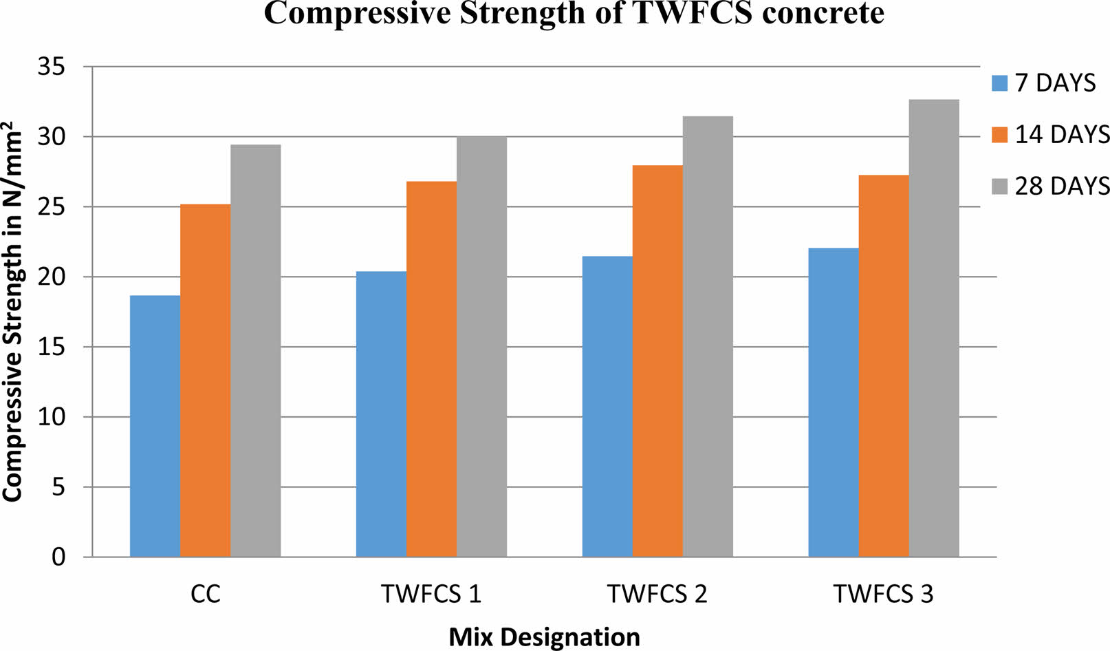
The Compressive strength test was done on Regular Concrete and TWFCS concrete. The compression testing machine used was an Indian Make (Fine spavy associates & Engineers Private Limited) and TUF-C-1000 SERVO model. Using a compression testing machine with a capacity of 1000 KN, the strength was tested at various curing stages, including 7 days, 14 days, and 28 days. The compressive strength of the Conventional Concrete and TWFCS concrete for 7 days, 14 days and 28 days is displayed in Fig. 3.
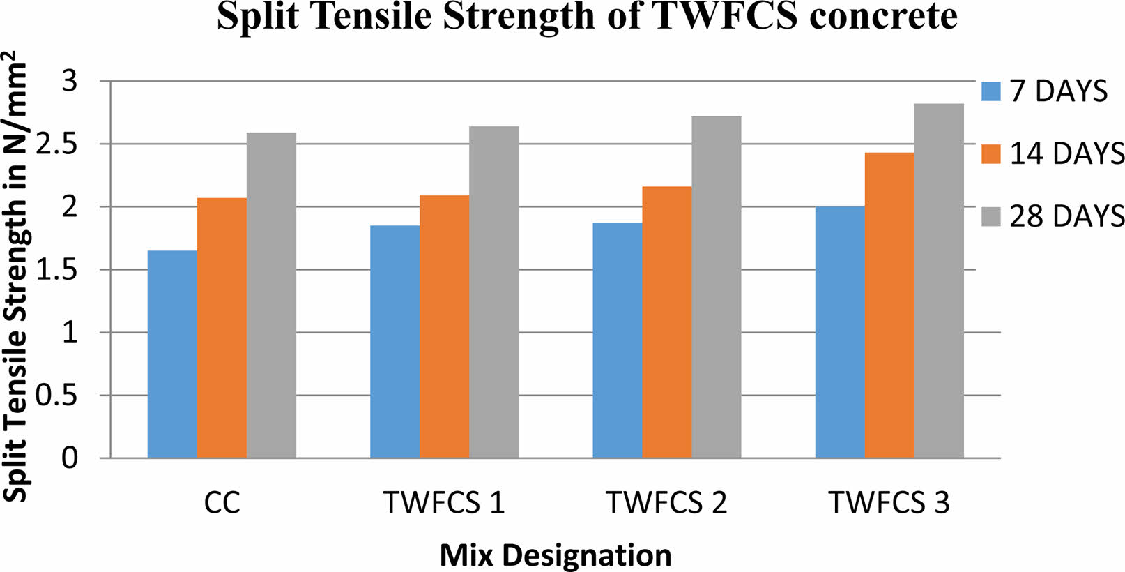
Split Tensile Strength
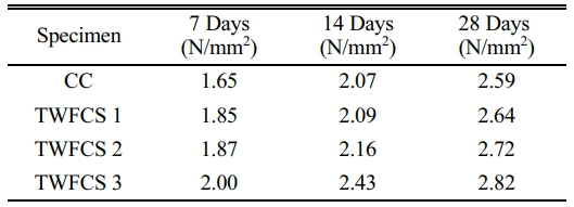
Conventional concrete was tested for split tensile strength, which partially replaced ceramic sand concrete and treated waste foundry concrete. Using a compression testing machine with a capacity of 2000 KN, the strength was tested at various curing stages, including 7 days, 14 days, and 28 days. It was carried out on a cylinder with a 150 mm diameter and 300 mm height. Table 2 displays the Split tensile strength of TWFCS concrete results. The TWFCS 3 sample had a higher tensile strength than the other two specimens and conventional concrete when foundry and ceramic sand replaced 20 percent of the fine aggregate. Figure 4 depicts a graphical comparison of split tensile strength after seven, fourteen, and 28 days.
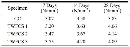
Flexural Strength
The flexural strength test was completed on Ordinary Concrete and in TWFCS concrete. Using a flexural strength testing machine with a capacity of 100 KN, the strength was evaluated at various stages of curing, including seven days, fourteen days, and 28 days. It was carried out on a prism specimen of 500 mm × 100 mm × 100 mm dimensions. Table 3 displays the findings regarding the flexural strength of TWFCS concrete. The TWFCS 3 sample had a higher flexural strength than the other two specimens and conventional concrete when foundry and ceramics sand replaced 20% of the fine aggregate.
Acid Attack Test
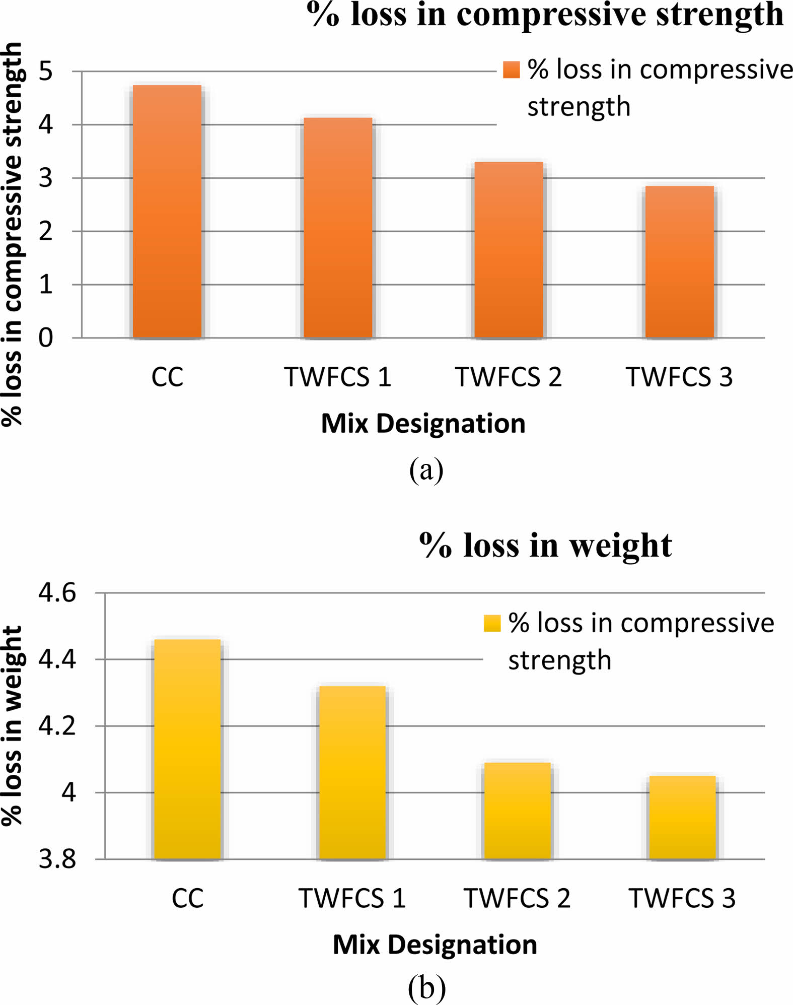
The acid attack test was directed according to ASTM C267-01 2012. After being cast, the 150 mm TWFCS concrete cube specimen was cured for 28 days before being removed and dried for one day. After 28 days of curing in water, the concrete cube specimens were measured for their weight. The TWFCS concrete cubes were subjected to a 28-day acid attack test by being submerged in diluted acid and water. Sulphuric acid with a pH of 2.0 and a water content of 5% was added. It was guaranteed that the pH of water to be kept up with for 28 days. After that, the specimens were tested for compressive strength by submerging a concrete cube in acid for 28 days with a variety of replacements of M25 grade. Fig. 5(a) shows the results, and Fig. 5 (b) shows the percentage loss of weight.
The findings revealed that TWFCS concrete had a lower percentage loss of compressive strength than conventional concrete. As per [36], the acid attack prompts the draining of mixtures of calcium in the concrete glue during the course of hydration in concrete as well as the presence of calcium in the calcareous total diminished the primary strength of the substantial and impacted the solidness. Additionally, it was discovered that as the concrete TWFCS percentage increased, so did the percentage of weight loss. This is because of the decrease in the porosity of cement wherein the pores get filled by the fine TWFCS particles.
Alkaline Attack Test
The alkaline test was carried out in accordance with the specifications of ASTM D1141. At 28 days, both conventional concrete and TWFCS concrete had the same percentage loss in weight and strength. To decide the obstruction of TWFCS substantial blends to the basic assault, they are cured in soluble water having 5% of Sodium Hydroxide (NaOH) arrangement by weight of water. The TWFCS substantial solid shapes were restored in water for 28 days. It is then taken out from the water tank following 28 days and permitted to dry for one day. The heaviness of the TWFCS cubes was taken submerging it in the antacid water. After that, the cubes spent 28 days submerged in the alkaline water. Throughout the test period, it was made certain that the alkalinity of the water would not change. After 28 days, the concrete cubes were removed and tested for compressive strength. Tables 4(a) and 4(b) present a breakdown of the obtained outcomes.
Rapid Chloride Permeability test
In accordance with ASTM C 1202-12, the Rapid Chloride Permeability Test was carried out. The consequences of RCPT for TWFCS concrete is displayed in Table 5. The decrease in the coulomb value with an increasing proportion of Waste Foundry and Ceramics Sand suggests that the density of TWFCS concrete increases as the replacement percentage rises. The results were obtained for 28-day-old TWFCS concrete. All TWFCS concrete mixtures fall into the low permeability category between 1000 and 2000, according to ASTM C 1202-12. The chloride ion's low permeability is essential for good durability. According to [37], the fact that chloride penetrates TWFCS concrete less than conventional concrete suggests that concrete has become denser and less permeable. TWFCS's finer particles make a good filler and fill in the spaces between concrete materials, making the internal structure stronger. The results of this investigation concur with those of this study.
SEM Analysis
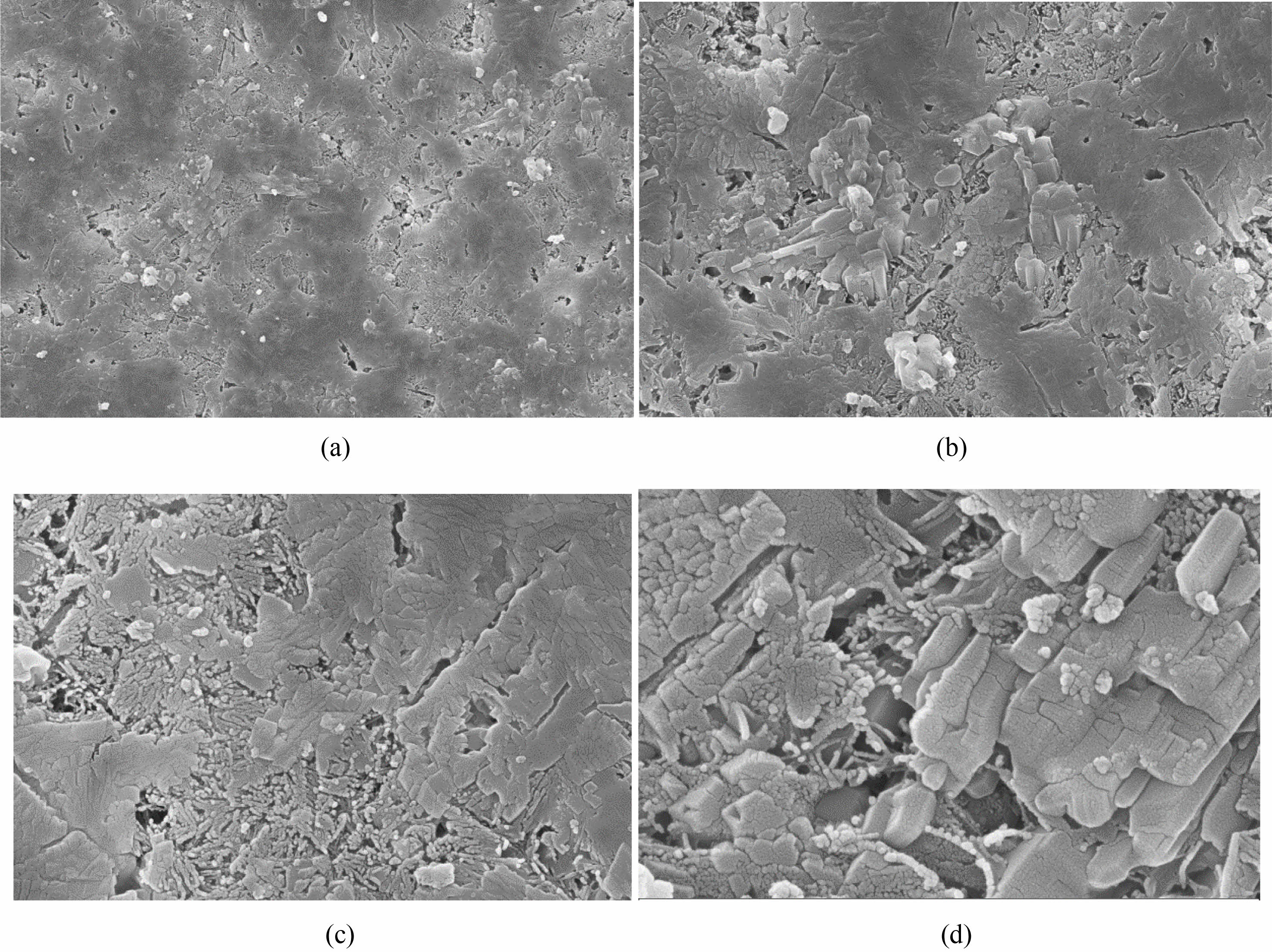
The Surface Morphology of the TWFCS concrete can be examined using SEM analysis. The Concrete cube specimens were tested in the Scanning Electron Microscope equipped with EDAX. The resolution of the lens is 1.5 mm. The TWFCS concrete was found to have different shapes of grains such as rounded, sub-rounded and of angular in shape. They were also found to be in different sizes. It was also observed that the TWFCS concrete does not have any curved pattern or scratches. The observed sample reveals the existence of carbon particles that have been deposited on the surface, exhibiting noticeable ridges. These particles exhibit a variety of shapes and sizes. The main reason behind this is the densified grains of silica in the concrete [38]. With higher magnification, the silicates which were packed closely were found [39]. Figure 6 (a), (b), (c) and (d) shows the images of SEM of Conventional Concrete and TWFCS Concrete of different percentages respectively.
XRD Analysis
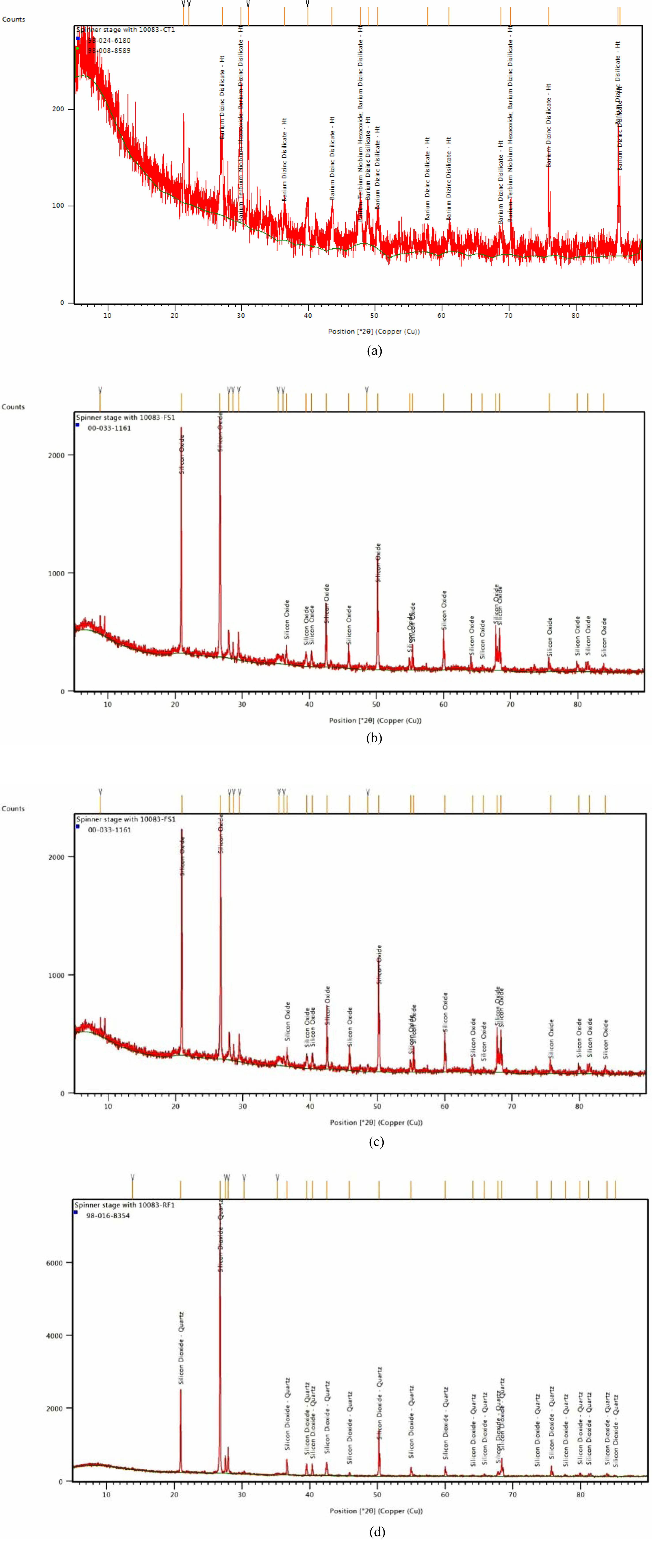
The TWFCS concrete samples were crushed by using pestle-mortar to form as fine powder after the curing period of concrete. The samples which are powdered were analyzed in the powder X-ray diffractometer. The spectrum of XRD were taken in the range between 2h = 10θ TO 2h = 80θ. This study showed that there is an increase in the percentage of strength due to the silicate formation in its new phase inside the matrix of the concrete. The pattern list Conventional Concrete showed that the crystal structure to be tetragonal and no formation of silica are found, whereas in TWFCS 1 concrete, Barium DiZinc Disilicate compound was formed with the crystalline structure to be Orthorhombic. The figure provides clear evidence that the diffraction angle (2θ) reaches its highest point between 12 and 22°. With increasing temperature, the diffraction angle (2θ) corresponding to the diffraction peak undergoes a gradual shift towards larger angles. Additionally, the width of the diffraction peak gradually decreases. Also, the TWFCS 2 concrete showed its crystalline structure to be hexagonal with the major compound being Silicon Oxide. The TWFCS 3 concrete was found to have Silicon dioxide as major compound with its crystalline structure being hexagonal shown in Fig. 7 (a), (b), (c) and (d).
|
Fig. 3 Compressive Strength of TWFCS concrete. |
|
Fig. 4 Split Tensile Strength of TWFCS concrete |
|
Fig. 5 (a) Percentage of Strength loss under Sulphuric Acid Environment, (b) Percentage of weight loss under Sulphuric Acid Environment. |
|
Fig. 6 (a) SEM image of CC, (b) SEM image of TWFCS 1, (c) SEM image of TWFCS 2, (d) SEM image of TWFCS 3 |
|
Fig. 7 (a) XRD image of CC, (b) XRD image of TWFCS 1. |
|
Table 4 (a) Percentage of strength loss under alkaline environment |
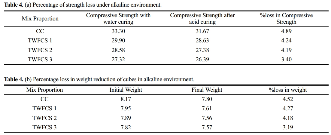
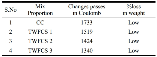
The results indicate that the compressive strength of Treated Waste Foundry and Ceramics Sand (TWFCS) concrete increases with a higher percentage of TWFCS compared to conventional concrete. The maximum compressive strength was observed in TWFCS 3, which consisted of 20% TWFCS and 80% M-Sand The flexural strength of TWFCS concrete was also highest in TWFCS 3, with a value of 4.89 N/mm2 at 28 days. When exposed to H2SO4 environment, TWFCS 3 concrete exhibited a lower percentage of compressive strength loss compared to conventional concrete. The weight loss percentage in TWFCS 3 mix was also 10% less compared to normal concrete cubes. Furthermore, in an alkaline environment, TWFCS 3 concrete experienced a 30.47% reduction in compressive strength compared to conventional concrete, along with a 29.42% lower weight loss percentage. TWFCS concrete demonstrated good resistance to chloride ion penetration, particularly TWFCS 3 with 20% TWFCS and 80% M-Sand, showing a 22.67% lower penetration compared to conventional concrete. Surface Morphology analysis of TWFCS concrete revealed tightly packed particles inside the pores of the concrete without curved scratches or patches under higher magnification. XRD analysis confirmed the formation of good C-S-H gel in TWFCS concrete, which contributes to its hardening and improved strength. Based on the findings, it can be concluded that concrete incorporating 20% TWFCS as a fine aggregate replacement performs effectively under various environmental conditions. This usage of TWFCS not only addresses challenges in the metal industries but also contributes to the production of greener concrete.
- 1. R. Siddique and E.-H. Kadri, Constr. Build. Mater. 25[8] (2011) 3257-3266.
-

- 2. C. Thamilpriyaa and G. Elangovan, J. Ceram. Process. Res. 24[3] (2023) 554-559.
-
- 3. S. Monosi, F. Tittarelli, C. Giosuè, and M.-L. Ruello, Constr. Build. Mater. 44 (2013) 260-266.
-
- 4. K. Sabarinathan and G. Arunkumar, J. Ceram. Process. Res. 24[2] (2023) 390-396.
-
- 5. G. Singh and R. Siddique, Constr. Build. Mater. 26[1] (2012) 416-422.
-
- 6. A. Anitha, V.G. Kalpana, and P. Muthupriya, J. Ceram. Process. Res. 24[1] (2023) 182-189.
-
- 7. N. Gurumoorthy and K. Arunachalam, Constr. Build. Mater. 123 (2016) 184-190.
-
- 8. American Society for Testing and Materials (ASTM). Standard Test Method for Iron Staining Materials in Lightweight Concrete Aggregates (ASTM C641-17). West Conshohocken, USA, 2017.
-
- 9. S.H. Eom, J.B. Lee, and S.H. Park, J. Ceram. Process. Res. 21[2], (2020) 164-169.
-
- 10. American Society for Testing and Materials (ASTM). Standard Specification for Lightweight Aggregates for Structural Concrete (ASTM C330/C330M-17a). West Conshohocken, USA, 2017.
-
- 11. B.-R.R.C. Anuradha, Int. J. Sci. Dev. Res. 4[9] (2016) 2321-0613.
- 12. M.-K. Dash, S.-K. Patro, and A.-K. Rath, A.K, Int. J. Sustain. Built Environ. 5[2] (2016) 484-516.
-
- 13. R. Bakis, H. Koyuncu, A. Demirbas, Waste Manag. Res. 24[3] (2016) 269-274.
-
- 14. Ordinary Portland Cement, 53 grade-specification”, Bureau of Indian Standards, New Delhi, (2013) IS: 12269-1987.
- 15. “Methods of test for Aggregates for concrete, Part-III specific gravity, density, voids, absorption and bulking”, Bureau of Indian Standards, New Delhi, (1963) IS: 2386
- 16. N.-K. Bairagi, H.-S. Vidyadhara, and K. Ravande, Constr. Build. Mater. 4[4] (1990) 188-193.
-
- 17. G. Kaur, R. Siddique, and A. Rajor, Constr. Build. Mater. 38 (2013) 94-100.
-
- 18. S. Fiore and M.-C. Zanetti, Am. J. Environ. Sci. 3[3] (2007) 135-142.
-
- 19. K. Packrisamy and K. Jayakumar, Arab. J. Geosci. 15[5] (2026) 407.
-
- 20. E.-A. Dayton, S.-D. Whitacre, R.-S. Dungan, and N.-T. Basta, Plant Soil 329 (2010), 27-33.
-
- 21. M. Etxeberria, C. Pacheco, J.-M. Meneses, and I. Berridi, Constr. Build. Mater. 24[9] (2010) 1594-1600.
-
- 22. R. Lin and L. Pang, J. Ceram. Process. Res. 20[3], (2019) 231-240.
-
- 23. American Society for Testing and Materials (ASTM) C 267-01(2012): Standard test Method for Chemical Resistance of Mortars, Grouts, and Monolithic Surfacings and Polymer Concretes, 2012.
-
- 24. D. Maruthachalam, M. Gurunathan, I, Padmanaban, and B.-G. Vishnuram, J. Struc. Engg. 38[1] (2011) 1-9.
- 25. American Society for Testing and Materials (ASTM) D 1141: Standard Practice for the preparation of substitute Ocean Water.
-
- 26. A.B.M.A. Kaish, T.C. Odimegwu, I. Zakaria, and M.M. Abood, J. Build. Eng. 35 (2021) 102092.
-
- 27. G. Singh and R. Siddique, Constr. Build. Mater. 26[1] (2012) 416-422.
-
- 28. A.-A.M. Ismail, K. Kannadasan, P. Pichaimani, H. Arumugam, and A. Muthukaruppan, J. Clean. Prod. 264 (2020) 121689.
-
- 29. F.F.G. de Paiva, J.R. Tamashiro, L.H.P. Silva, and A. Kinoshita, Constr. Build. Mater. 285 (2021) 122833.
-
- 30. P.O. Awoyera, J.M. Ndambuki, J.O. Akinmusuru, and D.O. Omole, HBRC Journal 14[3] (2018) 282-287.
-
- 31. R.-J. Daniel and S.-P. Sangeetha, Mater. Today: Proc. 45 (2021) 6603-6608.
-
- 32. S. Karthikkrishnan, and D.-R. Senthamarai, In National conference on recent developments in concrete technology, Government college of Technology, Coimbatore-641013, (2016).
- 33. F. Pacheco-Torgal and S. Jalali, Constr. Build. Mater. 24[5] (2010) 832-838.
-
- 34. A.-R. Pradeep, and M.-B. lingana Gowda, IOSR J. Mech. Civ. Eng. (2016) 22278-1684.
-
- 35. D.-S. Vijayan, C. Nivetha, P. Dinesh Kumar, B. Saravanan, and V. Gokulnath, J. Green Eng. 10[6] (2020) 3084-3101.
- 36. G.-E. Arunkumar, K. Nirmalkumar, P. Loganathan, and V. Sampathkumar, Glob. Nest. J. 25[5] (2023) 126-135.
- 37. A.-S. Kumaraswamy, K. Nirmalkumar, V. Sampathkumar, and S. Karthikeyan, J. Environ. Prot. Ecol. 23[2] (2022) 616-623.
- 38. S. Velusamy, A. Subbaiyyan, K. Ramasamy, M. Shanmugamoorthi, V. Vellingiri, Y. Chandrasekaran, and V. Murugesan, Mater. Today: Proc. 65 (2022) 549-553.
-
- 39. M. Shanmugamoorthy, S. Velusamy, A. Subbaiyyan, R. Yogeswaran, R. Krishnanbabu, and R. Senthilkumar, Mater. Today: Proc. 65 (2022) 920-924.
-
- 40. A. Halicka, P. Ogrodnik, and B. Zegardlo, Constr. Build. Mater. 48 (2013) 295-305.
-
- 41. S. Siddique, S. Shrivastava, and S. Chaudhary, Eur. J. Environ. Civ. 23[2] (2019) 212-225.
-
 This Article
-
2023; 24(4): 714-722
Published on Aug 31, 2023
- 10.36410/jcpr.2023.24.4.714
- Received on May 31, 2023
- Revised on Jul 28, 2023
- Accepted on Jul 29, 2023
Services
- Abstract
introduction
materials
methodology
mix design
role of foundry sand and ceramics in construction
results and discussion
conclusion
- References
- Full Text PDF
Shared
Correspondence to
- K.V. Boobala Krishnan
-
Department of Civil Engineering, Dr.N.G.P Institute of Technology, Coimbatore – 641048
Tel : +91 9942535500 - E-mail: boobalakrishnan007@gmail.com
Clean-Energy Research Institute(CRI), Hanyang University, 222, Wangsimni-ro, Seongdong-gu, Seoul, 04763, Korea
E-mail: jcpr@hanyang.ac.kr