


- Experimental and numerical analysis of tensile and flexure tests on a hybrid Aramid/E glass composites
Kalyani Gurrama and Pannirselvam N.b,*
aResearch Scholar, Department of Civil Engineering, SRM Institute of Science and Technology, Kattankulathur -603203, Chengalpattu District, Tamil Nadu, India
bAssociate Professor, Department of Civil Engineering, SRM Institute of Science and Technology, Kattankulathur -603203, Chengalpattu District, Tamil Nadu, IndiaThis article is an open access article distributed under the terms of the Creative Commons Attribution Non-Commercial License (http://creativecommons.org/licenses/by-nc/4.0) which permits unrestricted non-commercial use, distribution, and reproduction in any medium, provided the original work is properly cited.
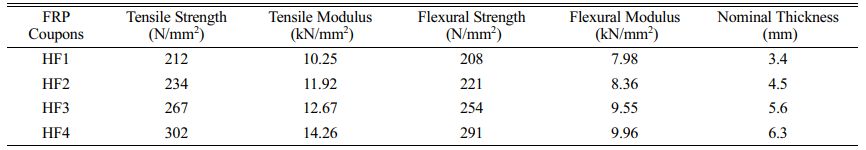
This paper focuses on the characterization of Hybrid Fiber Reinforced Polymer (HFRP) specimens made through a hand lay-up process, consisting of unidirectional Glass Fiber Reinforced Polymer (GFRP) and aramid Fiber Reinforced Polymer (AFRP) plies stacked in the same direction with an orientation angle of 0° and varying thicknesses. Tensile and flexure tests were conducted following ASTM standards, and the results were examined. Additionally, Finite Element Method (FEM) using ABAQUS software was employed to study the properties of these hybrid composites. A comparison between experimental and FEM results was made. The HF4 composite, with a high thickness, exhibited superior tensile strength and modulus of elasticity of 302 MPa and 14.26 GPa, respectively. The flexure test of the HF4 hybrid composite laminate demonstrated a flexible structure with a bending modulus of 9.96 GPa. The findings suggest that the inclusion of aramid fiber and glass plies as an extreme can significantly improve the characteristics of hybrid composites
Keywords: ABAQUS, Aramid, E-glass, Hybrid FRP, Tensile strength, Three‐point bending, Numerical simulation
Over the years, fiber-reinforced composite (FRP) materials have increased in popularity. Due to its superior mechanical qualities, such as lighter weight, exceptional flexibility, corrosion resistance, ease of manufacture, etc. when compared to other standard metallic materials, its application has significantly expanded Agarwal et al. [2]. FRP composite structures are frequently utilized in structural, marine and other applications where lightweight and durability are essential. The features of the planned composites must be thoroughly studied for these needs. Research and development studies have become more important in this regard for the everlasting secured and efficient usage of FRP composite constructions. Additionally, several substitutes for laminated composites are continually being investigated. By combining various kinds of natural or synthetic fibers, hybrid composite materials with higher structural qualities have made advancements in composite production technology Mallick [18], Kretsis [15]. This hybridization's objective is to develop a new material that benefits from the advantages of the individual fiber Gibson [9]. Compared to other previously produced materials, polymers reinforced with synthetic fiber have a higher mechanical strength and stiffness, which has led to an increase in their use in the automotive, aerospace, and defense industries Tsai and Hahn [26], Hamid et al. [19], Nunna et al. [22], Dehkordi et al. [7], Babukiran and Harish [3]. When compared to traditional composites, hybrid composites offer higher flexibility since they can include two or more reinforcement fibers in a single matrix, a single reinforcement fiber in several matrices, or multiple reinforcement fibers in numerous matrices Ghani and Mahmud [1]. The number of layers and kinds of fiber fabric used in the outer and inner layers of hybrid composites have a big effect on how dynamically the structure behaves. Numerous studies in this area have already been published by various experts Jain et al. [14], Jain et al. [11], Jain et al. [12], Jain et al. [13], Gautam and Pandey [8]. Because fiber’s shortcomings can be reduced by combining them with fibers that have superior matching properties utilizing the hybridization approach Chen et al. [5]. This hybridization can occur in at least three diverse ways: interlayer (layer by layer), intralayer and intrayarn. By stacking the various layers, the two materials are combined in an interlayer at the layer level Swolfs et al. [24], Patel [20]. In the intralayer design, both materials are blended more intimately since the yarns and tapes are mixed within each layer Srivathsan et al. (2017). Co-weaving both materials together is one method of accomplishing this. The intrayarn design, which allows two materials to be combined at the fiber level, is the final option Tan et al. (2014). Then, stacking sequences were improved, and hybrid composites were created to make up for each FRP's shortcomings.
According to Bhudolia et al. (2018), Aramid (Kevlar) has better elasticity but less ductility than glass fibers. As a result, the Glass/Kevlar blend can be used to increase the composite's flexibility. Additionally, a different basalt/glass combination increases the rate at which energy is absorbed after the impact of Sarasini et al. (2013), and basalt-based FRPs can be added to increase the fatigue life of such composites Colombo et al. (2012). Patel et al. [20] examined the various mechanical characteristics of basalt/glass polyester FRP, they concluded that while the flexural strength of the FRP was not improved by the combination of basalt and glass, another property, such as tensile strength, was comparable to that of their parent materials. Kevlar and glass laminates improve the resistance to bending, according to a study by Srivathsan et al. [23]. They noted that the accumulative sequence with a 0/90° orientation provided the highest level of bending resistance. They also concluded that hybrid FRP composites are stronger when they contain more Kevlar fibers. However, to the author’s knowledge, there have not been many studies on the Kevlar combination, making it impossible to assess the hybridization effect on flexural strength. Additionally, several research shows that enhancing the bending strength of FRPs involves the volume percentage of laminates as well. Also, as hybridization offers the potential benefits of both included fibers, the material with high stiffness should be positioned at the outer layer to have a higher flexural strength. But according to research, E-glass with carbon laminates significantly enhances flexural strength, fatigue and creep resistance Tan et al. [25], Gokuldass and Ramesh [10]. However, because carbon fiber is brittle and costly, hybrid FRP offers less ductility and is expensive. Saravanan et al. [27] The paper presents numerical analysis of stacking sequence in FRP laminate under dynamic resin behavior. However, limitations include the lack of experimental validation and limited consideration of other factors such as temperature and environmental effects, which may affect the accuracy and applicability of the findings in real-world scenarios. Wu et al. [28] presents a numerical simulation study on the ballistic performance of Al2O3/aramid-carbon hybrid FRP laminate composite structures under impact loading. However, the limitations of the study include the lack of experimental validation of the simulation results and the focus solely on numerical simulations without considering the influence of manufacturing variability or material characterization uncertainties, which may affect the accuracy and reliability of the findings. Madenci et al. [29] presents an experimental and theoretical investigation on the flexural performance of pultruded Glass Fiber Reinforced Polymer (GFRP) composite beams with damage analyses. However, the limitations of the study may include potential limitations in the representativeness of the experimental results to real-world applications and the generalizability of the findings to other types of composite materials or structural configurations. Stephen et al. [30] presents an experimental and numerical study on energy absorption and damage assessment of non-hybrid and hybrid fabric epoxy composite laminates. Sivaperumal et al. [31] with the use of compression moulding, the GFRP is created. The grey relational analysis (GRA) determines the ideal machining parameters. However, the limitations of the study include the lack of comprehensive characterization of the hybrid composite's mechanical properties and the absence of long-term durability testing to assess the material's performance over time.
In this study, hybrid composites reinforced with Kevlar and E-glass polymers were created and the flexural strength was examined experimentally using the tensile and three-point bending test. Combining ultimate strain and impact capabilities with cost-effective advanced composite material is possible with hybrid composites. A fraction of E-glass and other low-modulus fibers can be added to high-modulus fiber composites to improve their ultimate strain and impact properties. The in-plane strengths of hybrid composites relative to those of high modulus fiber composites could potentially decrease because of such an arrangement. By altering the volume proportion of the composite and the order in which the various plies are stacked, a hybrid composite can have different mechanical properties. Due to their high specific modulus, fibers made of carbon or boron are frequently employed in aeronautical applications. However, compared to ordinary steel alloys or glass reinforced composites, composites that consist of high modulus fibers often have lower impact strengths. Unidirectional hybrid fiber has received much less attention than woven fabrics in studies on flexural behavior hybrid laminates in the literature. It should also be highlighted that lowering the cost of the materials is one reason for employing a hybrid composite structure. The purpose of this study was to examine the interply hybrid Kevlar/glass composite laminate’s tensile, flexural and cost-effectiveness properties. The effects of hybrid ratio, stacking order and fiber mix on mechanical properties were systematically investigated. A finite element model was built to simulate the damage behavior in each layer of the hybrid laminate under loading. This study looked into the interply hybrid glass/aramid composite laminate’s tensile and flexural properties. The effects of hybrid ratio, layer counts and fiber combination on tensile and flexural properties were investigated.
Research problem and its significance:
The current investigation aims to study the mechanical properties of Hybrid Fiber Reinforced Polymer (HFRP) composites made using a hand lay-up process with varying thicknesses and stacking orientations, and compare the experimental results with Finite Element Method (FEM) simulations using Abaqus software.
Significance: The research findings will provide valuable insights into the behavior of HFRP composites, specifically the effects of incorporating unidirectional Glass Fiber Reinforced Polymer (GFRP) and aramid Fiber Reinforced Polymer (AFRP) plies. The results can contribute to the development of improved composite materials for various engineering applications, where high tensile strength, modulus of elasticity, and flexural properties are critical, and potentially lead to more efficient and durable structural designs.
Research Objectives:
• Investigate the mechanical properties of hybrid fiber reinforced polymer (HFRP) composites made with unidirectional glass fiber reinforced polymer (GFRP) and aramid fiber reinforced polymer (AFRP) plies using ASTM standards.
• Compare the tensile and flexural properties of different thicknesses of HFRP composites using experimental tests and Finite Element Method (FEM) simulations in Abaqus software.
• Assess the effect of including aramid and glass fiber plies on the mechanical characteristics of HFRP composites and identify the composite configuration with the highest tensile strength, modulus of elasticity, and bending modulus.
Contributions of the Research:
• The research analyses the mechanical properties of Hybrid Fiber Reinforced Polymer (HFRP) composites made using a hand lay-up process.
• The paper conducted tensile and flexure tests according to ASTM standards and compared the experimental results with Finite Element Method (FEM) simulations
• The research highlighted the significant contribution of including aramid fiber and glass plies in HFRP composites, resulting in improved mechanical characteristics.
Components utilized in composites
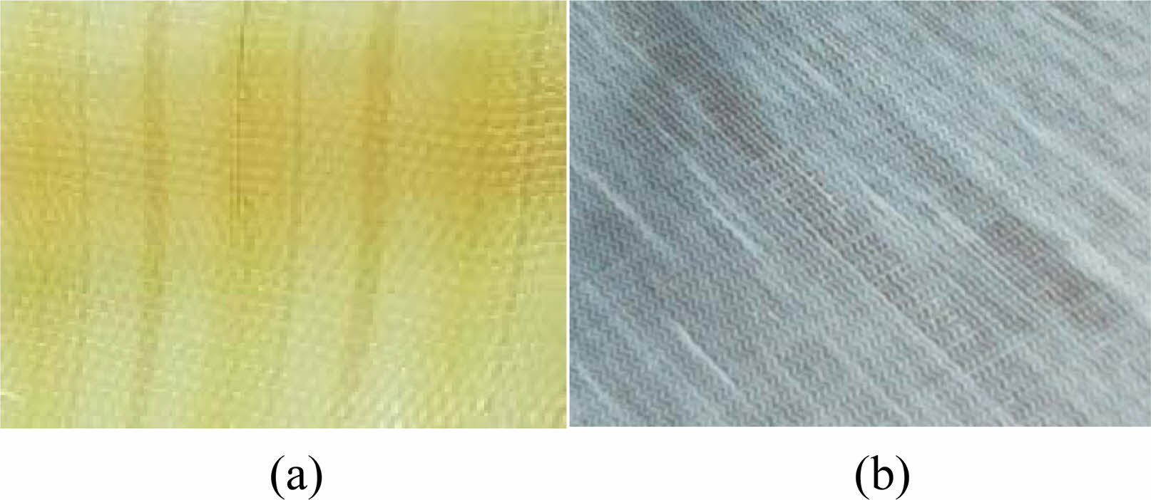
The study utilized unidirectional Kevlar and E-Glass reinforcements with areal (surface) densities of 1200 g/m2 and 300 g/m2, respectively, as shown in Fig. 1. Araldite Klear 4 Plus epoxy resin and a recommended hardener were used to create the matrix by following the supplier's instructions, which involved mixing epoxy resin and hardener curing agent (Klear 4+) at a ratio of 10:8 to achieve proper curing.
Composite fabrication procedure
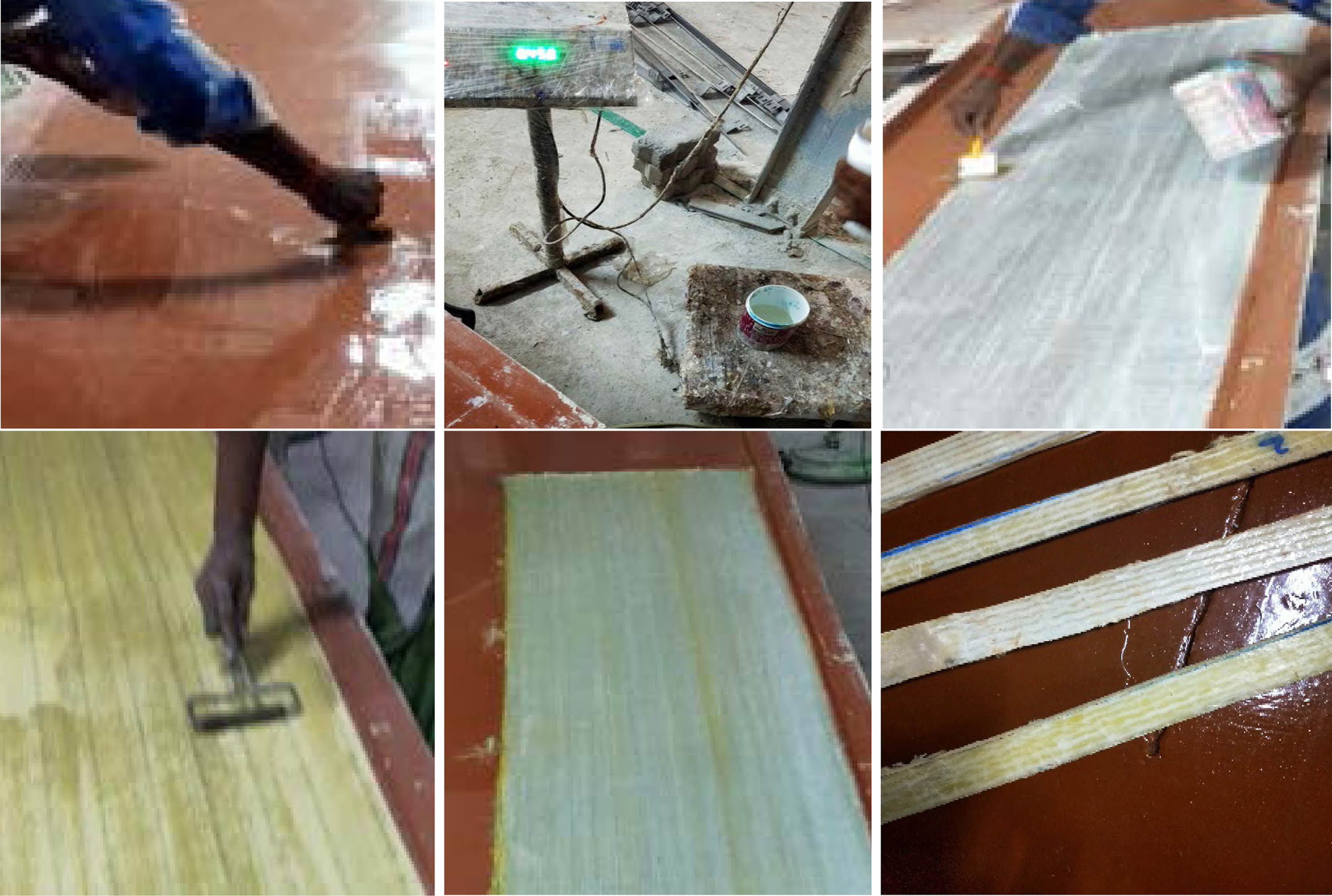
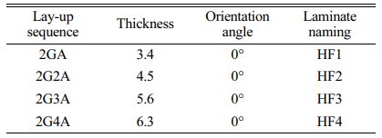
The hybrid composite laminate specimens were fabricated using the static compression method following either the hand lay-up or wet lay-up technique, as depicted in Fig. 2. In the wet lay-up method, the resin was applied using a brush, roller, or spray gun at room temperature after the fiber was cut and arranged in the mold. Achieving the desired thickness was accomplished by inserting spacers between the mold plates to ensure uniformity. This fabrication process, while cost-effective and relatively simple, requires high expertise to produce high-quality parts. Subsequently, the laminates were cured for 48 hours (approximately 2 days) at room temperature after an initial 1-hour curing under light pressure. Tables 1 and 2 provide details on the test standards and stacking order of the composite specimens, respectively, as per the research findings.
Table 1 shows the information about sample coupons.
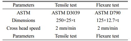
Table 2 represents the tensile and flexure standards according to ASTM.
Tensile test
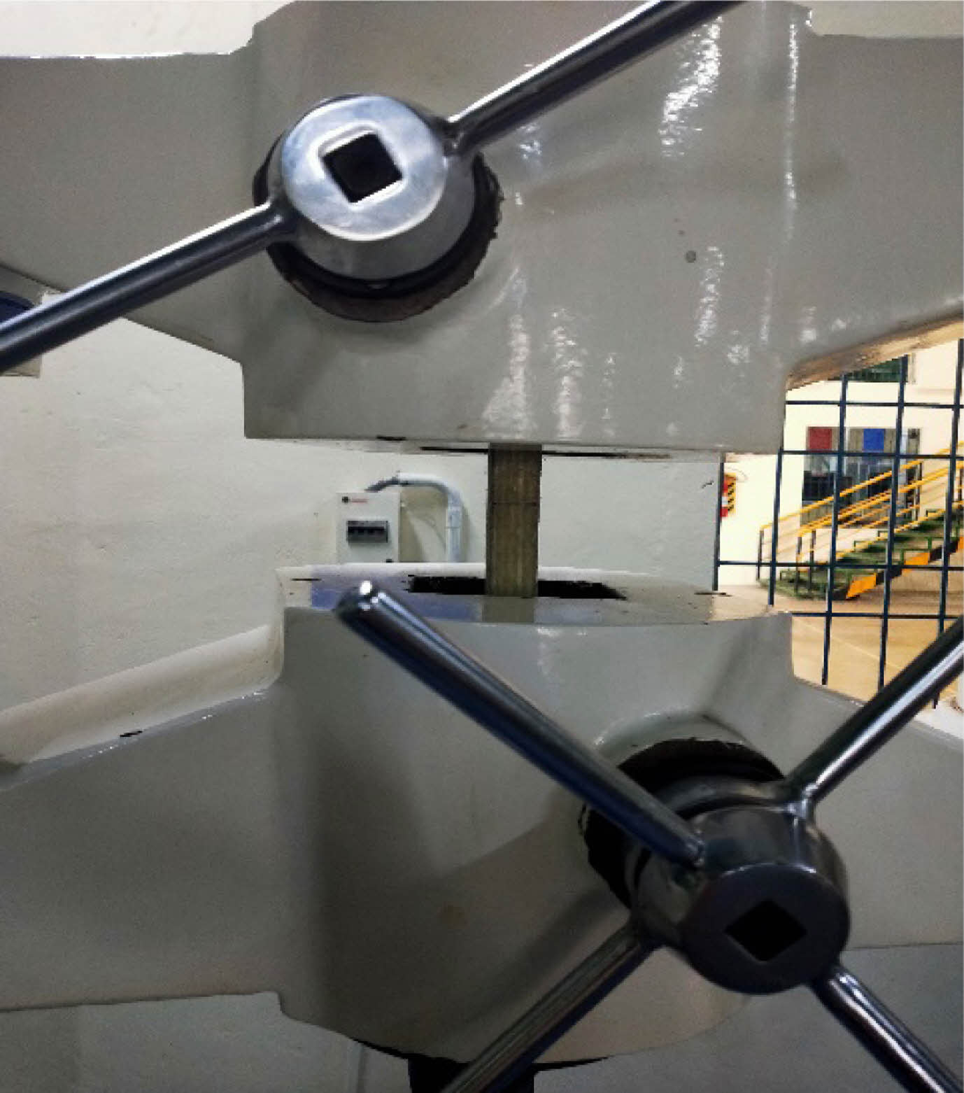
The laminate specimens for the tension test were prepared by carefully cutting them with a water jet and sizing them precisely using emery paper, as illustrated in Fig. 3. The specimens had dimensions of 250 × 25 × t mm3, and five identical samples were tested for each specimen to obtain the average results. The tensile tests were performed with a loading speed of 2 mm per minute, following ASTM D3039 standard for quasi-static tests at a strain rate of 5%/min, in order to ensure accurate and consistent measurements.
Flexure test
The bending modulus of the HF4 composite laminate was determined during the flexure test. The bending modulus, also known as flexural modulus, is a measure of a material's stiffness in bending. It is calculated using the force-displacement data obtained during the flexure test, where the specimen is subjected to bending.
The flexural modulus (E) can be calculated using the formula:

Where the beginning slope of the load-deflection curve is given by m, h is the laminate thickness and b is the specimen width. L is Span length.
By analyzing the force-displacement data from the flexure test of the HF4 composite laminate, the flexural modulus (E) was determined using the above formula. This value represents the stiffness of the HF4 composite laminate in bending, indicating its ability to resist deformation under flexural loads.
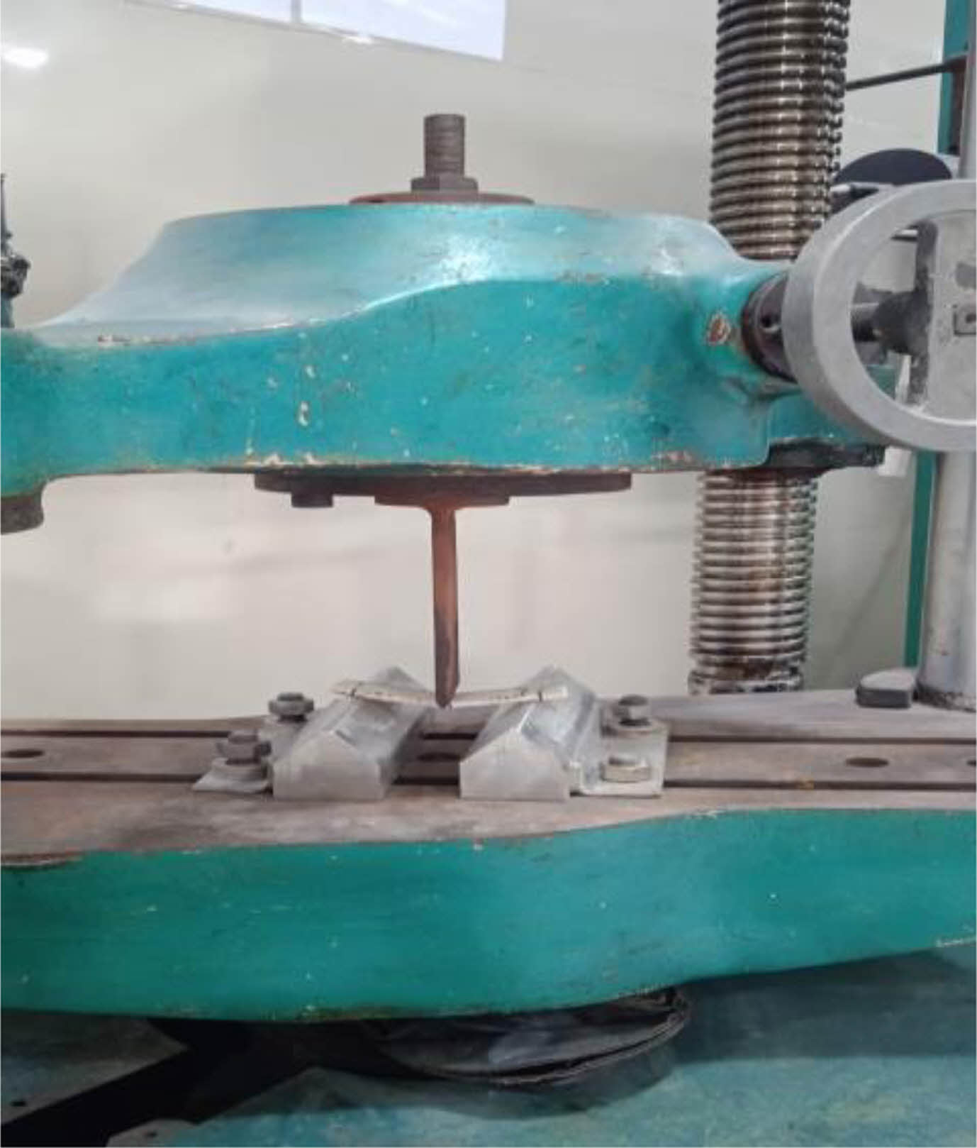
The flexural bending tests were conducted on all samples in accordance with ASTM D790 standards, using a feed rate of 2 mm/min. Hybrid composite specimens, oriented in the direction of loading, were tested as shown in Fig. 4. The specimens, with dimensions of 127 × 13 × h mm, were positioned on two pins with a span length of L. A force F was applied to the center of the specimen using one pin, and the test was conducted at a speed of 5 mm/min. The flexural stress (σf) and flexural modulus (E) were calculated using the force-displacement data, with a required span-to-depth ratio of 16:1.

The purpose of using Abaqus software in the presented work was to conduct Finite Element Method (FEM) simulations to study the mechanical properties and behavior of the Hybrid Fiber Reinforced Polymer (HFRP) composites under different loading conditions. Abaqus software was utilized to provide a numerical analysis and comparison with experimental results, aiding in the understanding of the composite's performance, validating the experimental findings, and providing insights into the structural behavior of the HFRP composites.
|
Fig. 1 Unidirectional lamina (AFRP in (a) and GFRP in (b)). |
|
Fig. 2 Manufacturing process of hybrid composites. |
|
Fig. 3 Tensile testing. |
|
Fig. 4 Flexure testing. |
Tensile test
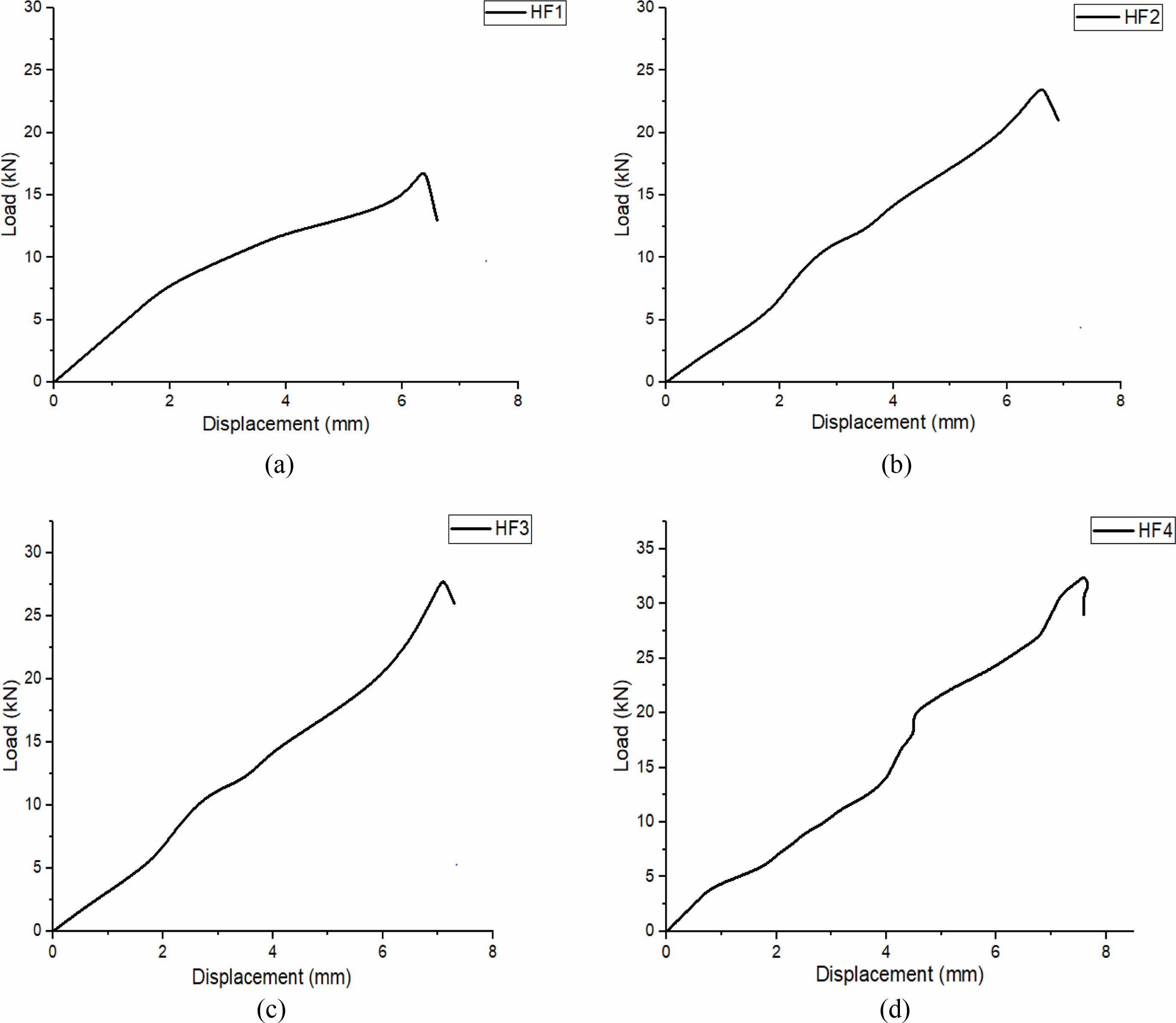
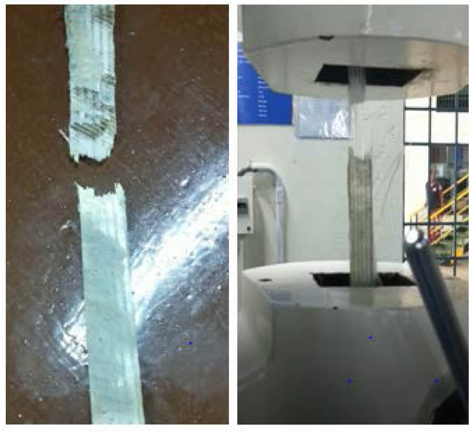
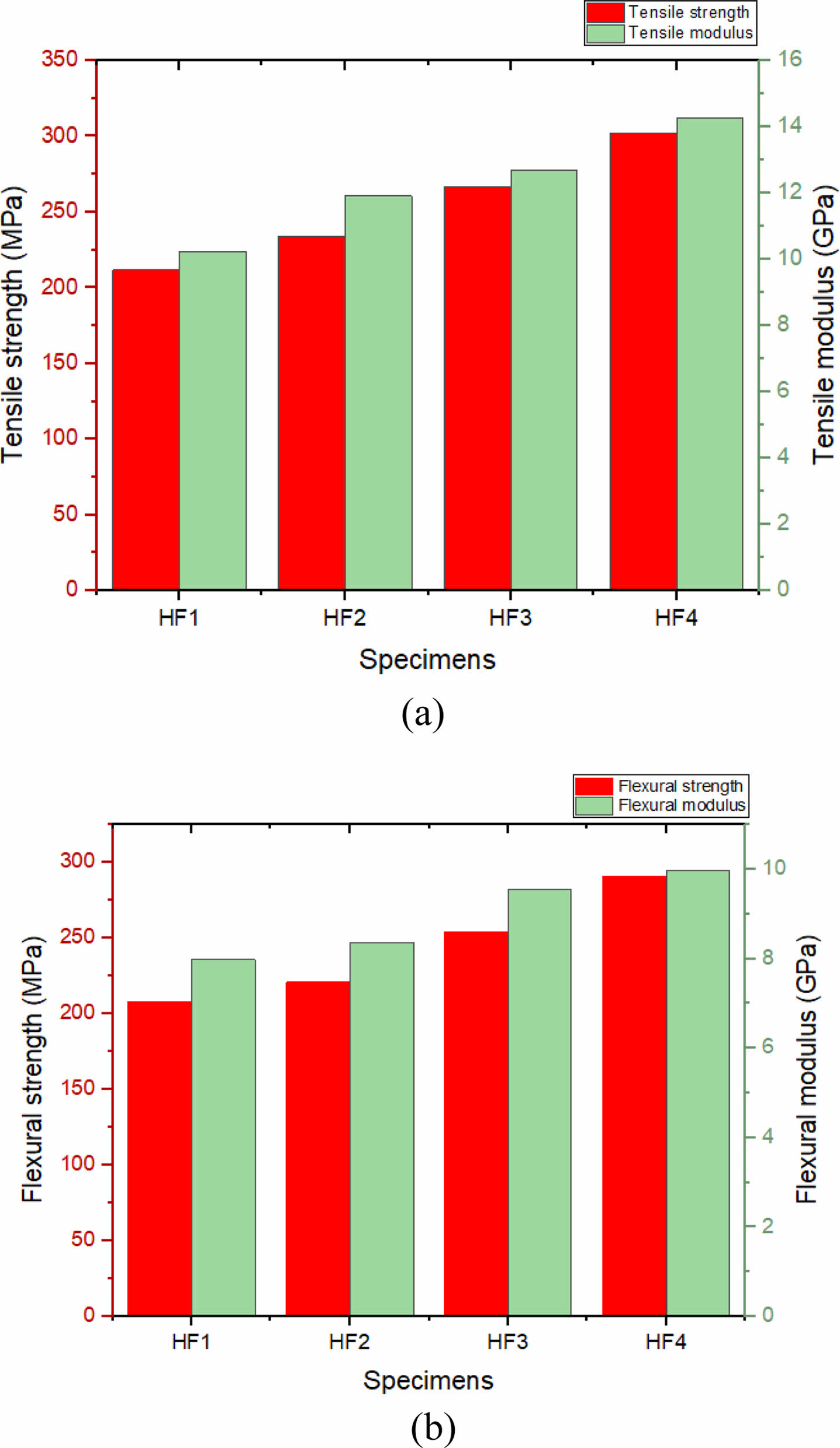
The strength and modulus of the fibers have an impact on the composite's tensile strength. HF1 laminate, the tensile strength and modulus are found to be lower than those of the other laminates. The use of aramid fiber plies in between glass fibers is shown to significantly boost the tensile strength (HF2, HF3 and HF4). The tensile strength and modulus of hybrid composite have increased because aramid fibers are stiffer and more powerful than glass fibers. Substantial fiber pull-out and fracture control hybrid laminate failure, as seen in Fig. 6, according to the observation of failed specimens. A contributing factor to this might be the fibers’ increased flexibility. The graph in Fig. 5 illustrates how the tensile properties of each coupon differ from one another. Fig. 9a and Table 3 display the variance in tensile strength and modulus for several hybrid composite laminates.
Flexure test
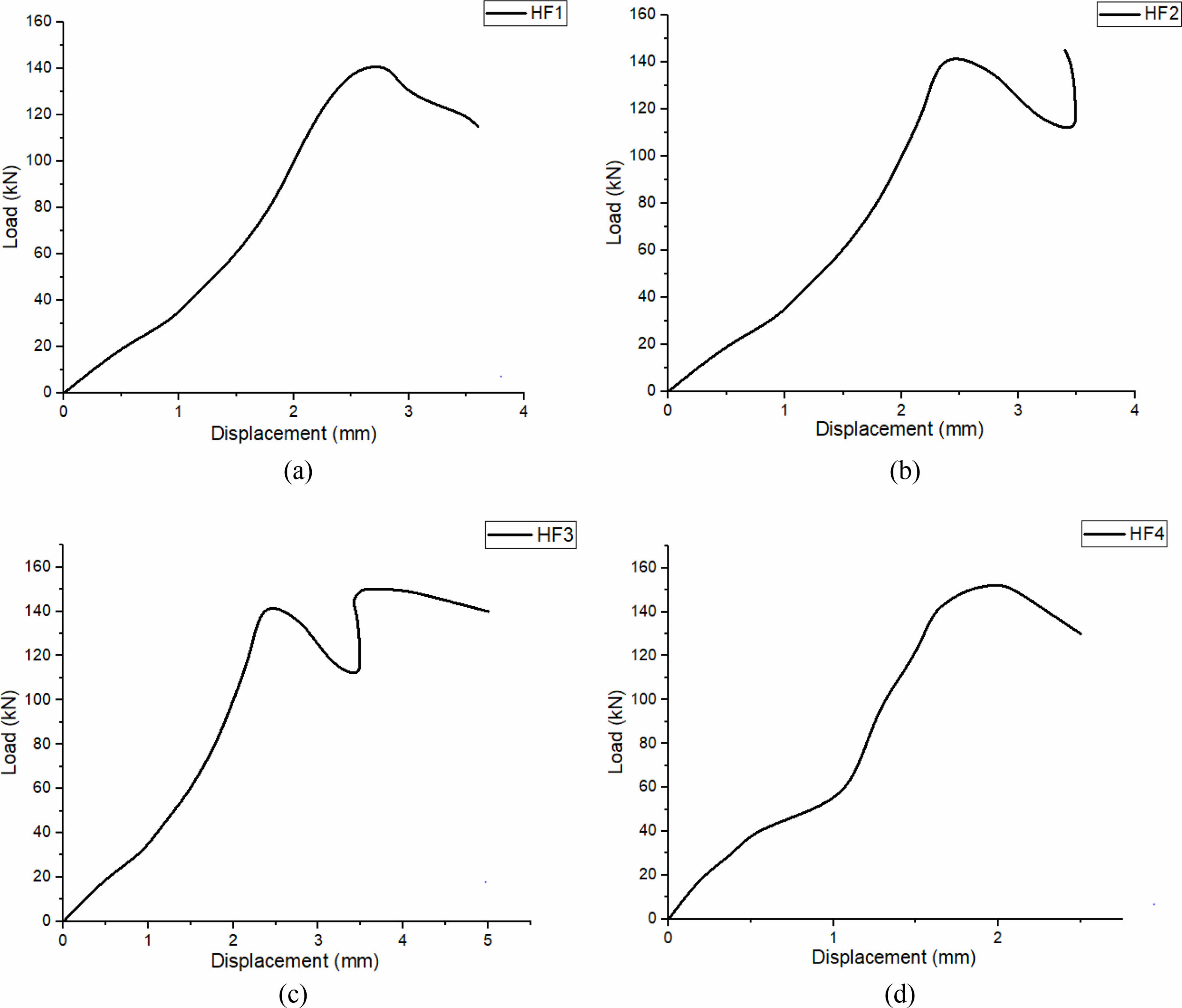
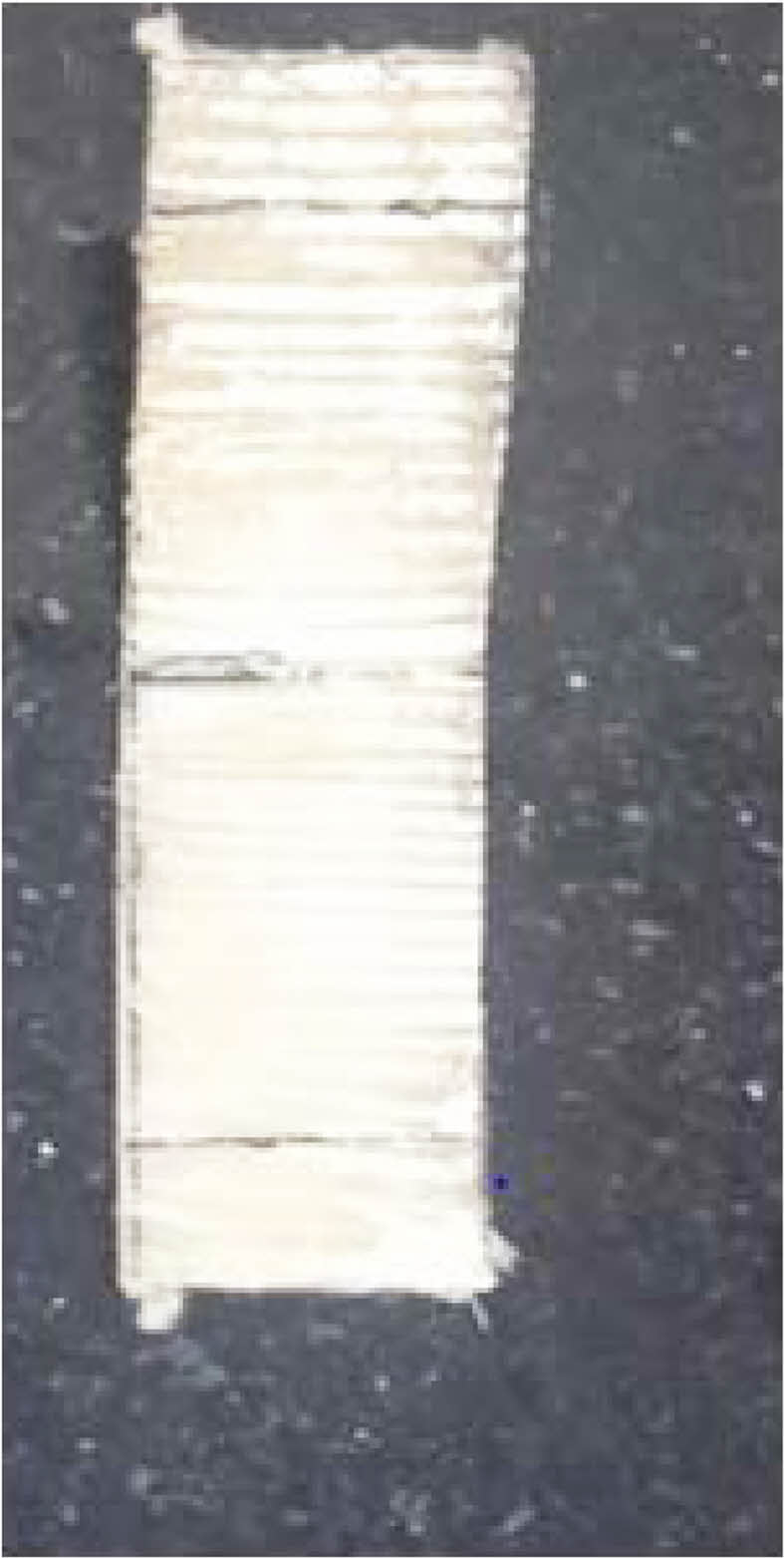
For the three-point bending test, the specimens were calibrated to a support span at a loading rate of 2 mm per minute. The location of the specimen's fracture is shown in Fig. 8. The load-deflection graphs for various hybrid composite laminates are shown in Fig. 7. All curves exhibit nonlinear behavior. The line where linearity breaks serve a warning sign that failure is about to start because a crack has appeared on the tension face. The flexural strength and modulus of laminates with various configurations are compared in Table 3 and Fig. 9b.
|
Fig. 5 Shows the results of tensile test with force-displacement diagrams: HF1 (a), HF2 (b), HF3 (c), and HF4 (d). |
|
Fig. 6 Failure of the specimen after tensile testing. |
|
Fig. 7 Results of the flexure test with force-displacement diagrams: HF1 (a), HF2 (b), HF3 (c), and HF4 (d). |
|
Fig. 8 Failure of the specimen after tensile testing. |
|
Fig. 9 compares the (a) tensile and (b) flexure strengths and moduli of a hybrid composite specimen. |
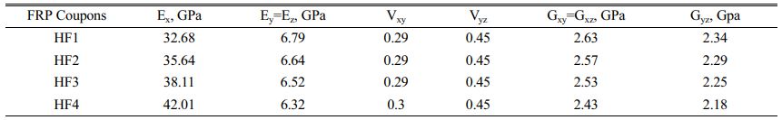
The hybrid Aramid/E-glass reinforced laminate's finite element (FE) model was created using the ABAQUS/Explicit programmed 2021. On laminated composite sheets, simulations of tensile and flexural behavior were run. The dimensions of these simulations matched those of the experiments carried out in the current study to compare test results. Based on the obtained experimental data and the rule of mixtures, the mechanical properties of the composite were determined and listed in Table 4 by using Chawla (1998); Lubliner et al. (1989). For the convergence analysis, many mesh configurations were considered. In general, mesh refinement is not necessary, according to FE simulations of tensile and three-point bending using different meshes, as illustrated in Fig. 9.
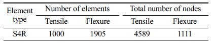
FRP sheets are modeled using four-node shell elements with reduced integration (S4R). A general static step with a one-second duration and automatic stabilization specifying a 0.0002 dissipated energy fraction was chosen. A generalized contact method with friction coefficients of 0.15 was created for the global contact and cohesive contact between the composite sheet and stiff boundary conditions. With a steady rise in time of less than 1e09s and a maximum of 105 increments, the calculation procedure was applied to each of the relevant elements in the FE model for the mechanical reaction of the composite. Table 5 gives details of meshing for both tensile and flexure tests.
The study's findings, which include the displacement distribution of various elements, are analyzed when the simulation is finished. The findings of the physical tests and the composite three-point bending simulation agreed to a very high degree. Due to the examination of the elastic limit, the exact component meshing, and the symmetrical test geometry as depicted in Figs. 10 and 11, this comparison has a high degree of accuracy. For tensile and flexural tests, the estimated percentage of a maximum disagreement between the finite element solution and experimental value is 5.78% and 2.48%, respectively.
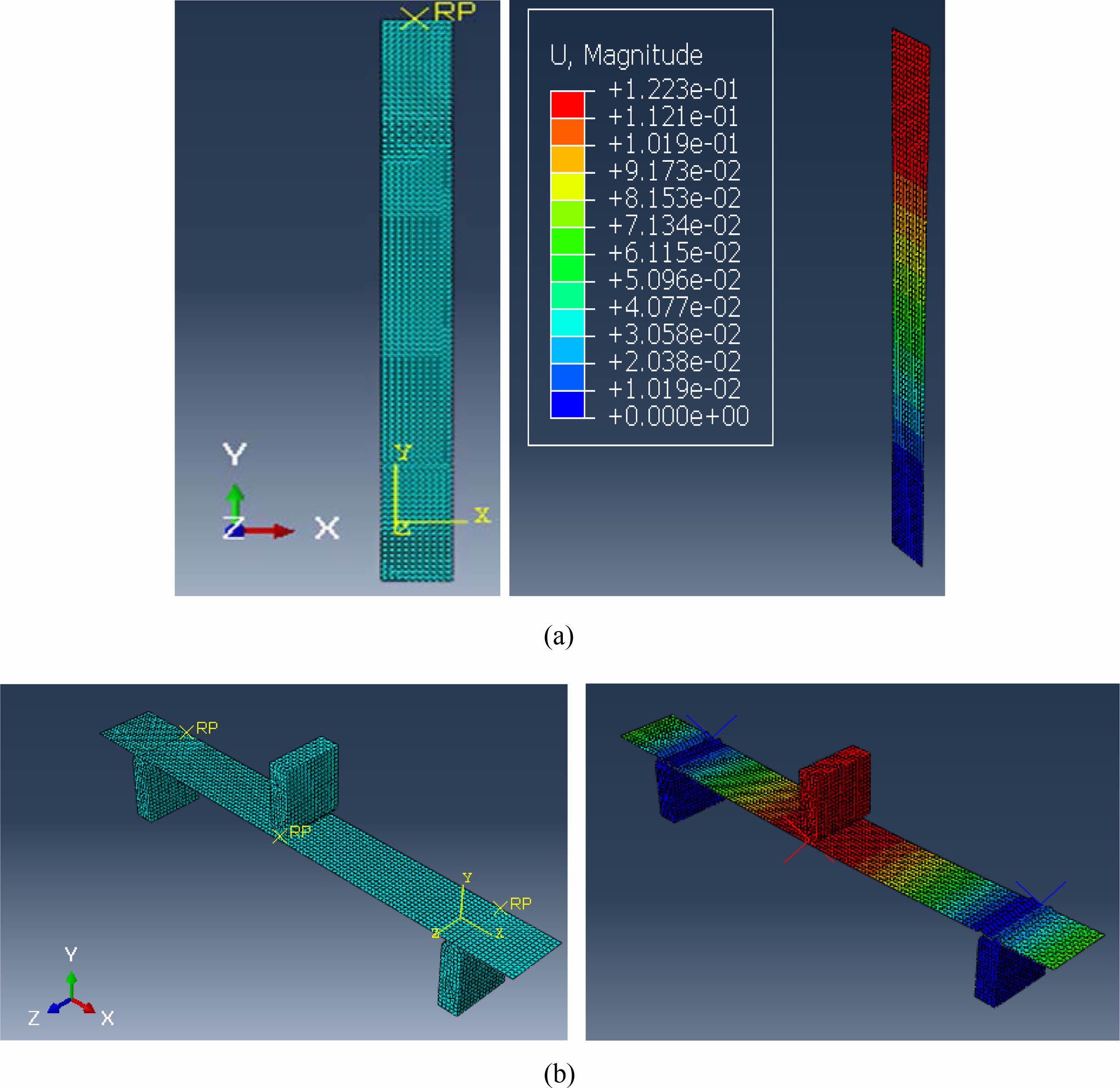
|
Fig. 10 FEM mesh results (a) Tensile (b) Flexure |
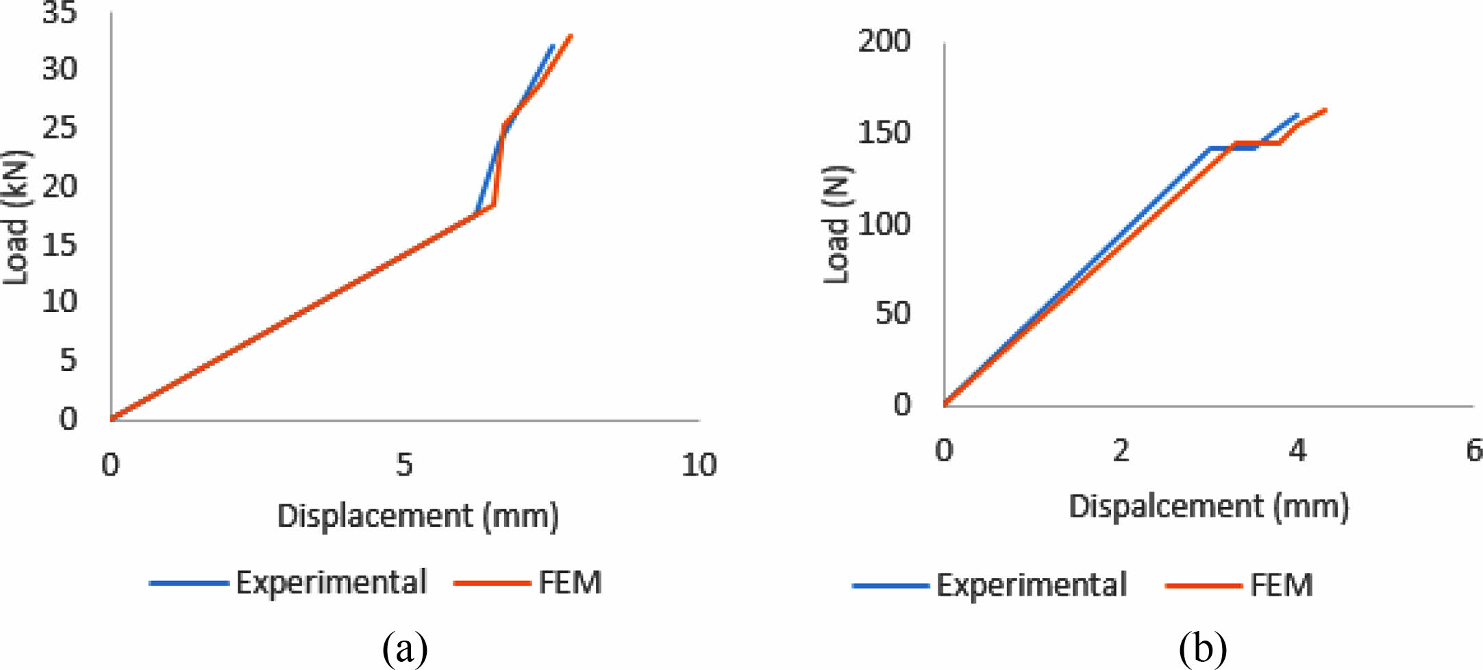
|
Fig. 11 Results of force-displacement for (a) tensile (b) flexure. |
Using the hand layup method, it has been experimentally and analytically assessed the number of layers that affects the tensile and flexural characteristics of hybrid glass/aramid fabric reinforced epoxy composites. Four hybrid composites in total, HF1, HF2, HF3, and HF4, were created. The findings of this investigation lead to the following conclusions.
1. The characteristics of the resulting hybrid composites are improved by adding aramid piles in between glass fiber composites.
2. The tensile and flexural strength of aramid rises with the addition of a number of layers.
3. A study of the qualities of all the laminates showed that the hybrid laminate (HF4), which has four aramid plies and the ideal configuration for achieving a balance between cost and characteristics is two extreme glass plies on either side (which increases with the increase in the number of glass layers).
4. The elastic range showed relatively consistent results when comparing modeling and experimental data. The findings of FEM analysis performed under identical conditions and using the same material in experimental tests indicate good agreement.
Future enhancements for the investigated hybrid fiber reinforced polymer (HFRP) composites could include optimizing the orientation angle and stacking sequence of the plies to further improve mechanical properties, as well as conducting additional testing under different loading conditions to evaluate their performance in specific applications.
No participation of humans takes place in this implementation process
No violation of Human and Animal Rights is involved.
No funding is involved in this work.
Conflict of Interest is not applicable in this work.
There is no authorship contribution
There is no acknowledgement involved in this work.
- 1. A.F. Ab Ghani, and J. Mahmud, Key Eng. Mater. 740 (2017) 31-40.
-

- 2. B.D. Agarwal, L.J. Broutman, and K. Chandrashekhara, in “Analysis and performance of fiber composites” (Wiley Publication, 2006).
- 3. B.V. BabuKiran and G. Harish, Int. J. Res. Aer. Mech. Eng. 2[1] (2014) 54-60.
- 4. S.K. Bhudolia, K.K.C. Kam, and S.C. Joshi, J. Ind. Text. 47[8] (2018) 1887-1907.
-
- 5. Q. Chen, Y. Zhao, Z.Zhou, A. Rahman, X.F. Wu, W. Wu, T.Xu, and H.Fong, Compo. Part B: Eng. 44[1] (2013) 1-7.
-
- 6. C. Colombo, L. Vergani, and M.J.C. Burman, Compo. Struc. 94[3] (2012) 1165-1174.
-
- 7. M.T. Dehkordi, H. Nosraty, M.M. Shokrieh, G. Minak, and D. Ghelli, Mater. Des. 43 (2013) 283-290.
-
- 8. G.D. Gautam and A.K. Pandey, Infrared Phys. Technol. 89 (2018) 203-217.
-
- 9. R.F. Gibson, Boca Raton, FL CRC Press (2016).
- 10. R. Gokuldass and R.J.S. Ramesh, Silicon 11[6] (2019) 2731-2739.
-
- 11. A. Jain, B. Singh, and Y. Shrivastava, Part C: J. Mech. Eng. Sci. 234[2] (2019) 620-634.
-
- 12. A. Jain, B. Singh, and Y. Shrivastava, J. Laser Appl. 31[3] (2019) 032017.
-
- 13. A. Jain, B. Singh, and Y. Shrivastava, Compo. B: Eng. 176 (2019) 107294.
-
- 14. A. Jain, B. Singh, and Y. Shrivastava, Arab. J. Sci. Eng. 45[2] (2020) 833-848.
-
- 15. G. Kretsis, Composites 18[1] (1987) 13-23.
-
- 16. A.V. Krishan Kumar Chawla, in “Composite Materials: Science and Engineering” (Springer, 1998) pp.303-316.
- 17. J. Lubliner, J. Oliver, S. Oller, and E. Onate, Int. J. Solid Struct. 25[3] (1989) 299-326.
-
- 18. P.K. Mallick, in “Fiber-reinforced composites: Materials, manufacturing, and Design. Boca Raton” (FL: CRC Press, 2007).
-
- 19. N.A. Hamid, N.H.N. Abdullah, M.R. Mansor, M.A.M. Rosli, and M.Z. Akop, J. Mech. Eng. Technol. 2[2] (2010) 1-15.
- 20. N. Patel, K. Patel, P. Gohil, and V. Chaudhry, Int. J. Appl. Eng. Res. 13[6] (2018) 4083-4088.
- 21. F. Sarasini, J. Tirillo, M. Valente, T. Valente, S. Cioffi, S. Iannace, and L. Sorrentino, Compos. Part A Appl. Sci. Manuf. 47 (2013) 109-123.
-
- 22. S. Nunna, P.R. Chandra, S. Shrivastava, and A.K. Jalan, J. Reinf. Plast. Compos. 31[11] (2012) 759-769.
-
- 23. A. Srivathsan, B. Vijayaram, and R. Ramesh, Mater. Today: Proceed. 4[8] (2017) 8928-8937.
-
- 24. Y. Swolfs, L. Gorbatikh, and I. Verpoest, Compos. Part A Appl. Sci. Manuf. 67 (2014) 181-200.
-
- 25. C.L. Tan, A.I. Azmi, and N. Muhammad, Adv. Mater. Res. 980 (2014) 8-12.
-
- 26. S.W. Tsai and H.T. Hahn, Technomic Publishing (2018) 356-360.
- 27. W.S.R. Saravanan, A. Krishnamoorthy, S. Manigandan, and P. Gunasekar, Today: Proceed. 16 (2019) 1168-1174.
-
- 28. S. Wu, Z. Xu, C. Hu, X. Zou, and X. He, Ceram. Int. 48[5] (2022) 6423-6435.
-
- 29. E. Madenci, Y.O. Ozkılıc, and L. Gemi, Compos. Struct. 242 (2020) 112162.
-
- 30. C. Stephen, A.H.I. Mourad, B. Shivamurthy, and R. Selvam, J. Mater. Res. Technol. 14 (2021) 3080-3091.
-
- 31. M. Sivaperumal, R. Thirumalai, S. Kannan, and Y.K. Rao, J. Ceram. Process. Res. 23[3] (2022) 404-408.
-
 This Article
-
2023; 24(3): 560-568
Published on Jun 30, 2023
- 10.36410/jcpr.2023.24.3.560
- Received on Mar 17, 2023
- Revised on Apr 14, 2023
- Accepted on Apr 27, 2023
Services
- Abstract
introduction
testimonial plan
the outcomes of the experiment
numerical analysis and validation
conclusion
- Ethics Approval and Consent to Participate
- Human and Animal Rights
- Funding
- Conflict of Interest
- Author Contributions
- Acknowledgements
- References
- Full Text PDF
Shared
Correspondence to
- Pannirselvam N.
-
Associate Professor, Department of Civil Engineering, SRM Institute of Science and Technology, Kattankulathur -603203, Chengalpattu District, Tamil Nadu, India
Tel : +91 7010168542 - E-mail: pannirsn@srmist.edu.in
Clean-Energy Research Institute(CRI), Hanyang University, 222, Wangsimni-ro, Seongdong-gu, Seoul, 04763, Korea
E-mail: jcpr@hanyang.ac.kr