


- Analyze the various effects of cutting tools in the machining of titanium alloy
D. Ananda Kumara,*, A. Murugarajanb and E. Mohanc
aDepartment of Mechanical Engineering, JCT College of Engineering and Technology, Pichanur, Coimbatore, Tamilnadu, 641105, India
bDepartment of Robotics and Automation, Sri Ramakrishna Engineering College, Vattamalaipalayam, Coimbatore, Tamilnadu, 641022, India
cDepartment of Mechanical Engineering, Shanmuganathan Engineering College, Arasampatti, Pudukkottai, Tamilnadu, 622507, IndiaThis article is an open access article distributed under the terms of the Creative Commons Attribution Non-Commercial License (http://creativecommons.org/licenses/by-nc/4.0) which permits unrestricted non-commercial use, distribution, and reproduction in any medium, provided the original work is properly cited.
Titanium alloy has dominated in mechanical-based industries due to its superior tensile strength, toughness, and corrosion resistance. This research involves the development of a wear model integrated with the FEM model. A numerical study and experimental work were conducted to variant tool nose radius, cutting speed, and feed rate in the machining of titanium alloy. The machining operation was properly simulated using Deform2D commercial-based software to predict the cutting force, tool wear, and cutting zone temperature. In addition, the same output response was assessed in the experimental technique by employing all geared lathes. In both the experiment and simulation conditions, the least cutting force was produced at the lowest feed rate and the smallest nose radius. It was noticed from the data that the cutting zone temperature at the cutting zone region was raised with an increase in the tool nose radius. Utmost tool wear was recorded at the minimal tool nose radius and minimum feed rate. Cutting speed plays a vital function in the evaluation of tool wear and nose radius in the prediction and assessment of cutting tool force and tool interface temperature. Tool wear study and surface morphology were fully explored with the assistance of SEM images
Keywords: Titanium, Tool wear, Cutting force, Deform 2D, Tool tip temperature, Simulation
Titanium alloys are widely used in aerospace, medical, and other high-performance applications due to their excellent strength-to-weight ratio, corrosion resistance, and biocompatibility. However, machining these materials can be challenging due to their high strength, low thermal conductivity, and tendency to work harden. The cutting tool is a crucial component in the machining process, and its properties have a significant impact on the efficiency, quality, and cost of the machined parts. In this analysis, we will examine the various effects of the cutting tool on the machining of titanium alloys, including tool wear, cutting forces, surface finish, and chip formation. Understanding these effects helps to optimize the machining process and improve the performance of the cutting tool. The manufacturing process that involves converting any shape of raw material into a cylindrical shape is known as turning an operation, which is well-known and widely used with the involvement of a lathe. The result of the cutting tool is to remove unwanted surplus materials from the raw materials into the desired shape and size.
The use of lubricants during the machining process helps to reduce cutting temperatures and tool wear. Mineral oil is a commonly used lubricant in machining operations because it is inexpensive and readily available. Nanofluids, which are suspensions of nanoparticles in a liquid lubricant, are more effective at reducing cutting temperatures and tool wear than mineral oil. This is because the nanoparticles in the nanofluid act as a heat sink, absorbing and dissipating heat away from the cutting zone. Additionally, the nanoparticles also help to reduce friction between the tool and the workpiece, which can further reduce tool wear.
The Usui wear model, also known as the Usui-Kato wear model, is a mathematical model that describes the wear of a cutting tool as a function of the cutting parameters and the properties of the workpiece material. This model is implemented in a numerical study to predict the wear of a cutting tool during machining. The cutting parameters are defined such as cutting speed, feed rate, and depth of cut. The properties of the workpiece material are determined such as hardness, Young's modulus, and Poisson's ratio. The Usui wear model equation is used to calculate the wear of the cutting tool as a function of the cutting parameters and the properties of the workpiece material. The predicted wear with the measured wear of the cutting tool is compared to validate the model. The Usui wear model plays a key role in the analysis of the cutting tool wear in the machining of titanium alloy. It allows us to predict the wear of the cutting tool as a function of the cutting conditions and the properties of the workpiece material. It is used to optimize the machining process, such as selecting the appropriate cutting parameters and tool material, to minimize tool wear and extend tool life. Additionally, it is also used to design new cutting tools with improved wear resistance.
In the machining of titanium alloys, various factors are varied to investigate their effect on the cutting tool wear, cutting forces, surface finish, and chip formation. Some of the factors that may be varied include:
1. Cutting speed: This is the speed at which the cutting tool moves across the surface of the workpiece. It is typically measured in meters per minute (m/min) or feet per minute (ft/min).
2. Feed rate: This is the speed at which the cutting tool moves along the cutting edge. It is typically measured in millimeters per revolution (mm/rev) or inches per revolution (in/rev).
3. Depth of cut: This is the distance that the cutting tool penetrates the workpiece. It is typically measured in millimeters (mm) or inches (in).
4. Tool geometry: This is the shape of the cutting edge and the rake angle of the tool.
5. Tool material: The material that the cutting tool is made of.
6. Coolant: The liquid or gas that is used to cool and lubricate the cutting tool.
These factors are controlled by using a CNC machine, or other precision machine tools, to ensure that the cutting conditions are consistent and repeatable during the experiment. Additionally, proper measurement techniques such as using a dial gauge or a laser sensor can be used to measure the cutting forces, surface finish, and chip formation. Tool wear can be measured by using a microscope or a profilometer.
The cutting speed can have a significant impact on tool wear and tool forces during the machining process. Higher cutting speeds lead to increased thermal loads on the cutting tool, which can lead to increased tool wear. Additionally, the increased cutting speed can lead to increased cutting forces, which can lead to increased stress on the tool and the machine. Lower cutting speeds reduce the thermal loads and cutting forces, but also increase the machining time. Thus, an appropriate cutting speed setting for a given machining operation is an important consideration to minimize tool wear and tool forces while maintaining an acceptable machining time.
The tool nose radius plays an important role in the machining of titanium alloy with an uncoated cemented carbide insert. A larger tool nose radius will result in a reduced contact area between the tool and the workpiece, leading to lower tool forces and less tool wear. However, a smaller tool nose radius will result in a higher contact area, leading to higher tool forces and more tool wear. The tooltip interface temperature will also be affected by the tool nose radius. A smaller radius will result in a higher temperature due to the increased contact area and friction, while a larger radius will result in a lower temperature. The tool nose radius also affects the surface finish of the machined part and the cutting-edge strength of the tool. Therefore, the selection of the tool nose radius is an important factor to consider when performing the machining of titanium alloy with an uncoated cemented carbide insert.
The titanium alloy used in the experimental study is composed of various elements in specific weight percentages. The alloy contains 4.22% V, 5.48% Al, 0.0625% Sn, 0.0028% Zr, 1.005% Mo, 0.369% C, 0.0222% Si, 0.0099% Cr, less than 0.001% Ni, 0.112% Fe, less than 0.02% Cu, 0.0386% Nb, and 90% Ti. These elements are combined to create a specific composition that is suitable for the machining process being studied.
Deform 2D software is used to simulate the machining process and predict the tool forces and tool wear. The software uses the Finite Element Method (FEM) to solve the complex interactions between the cutting tool and the workpiece. The benefits of using Deform 2D for this type of analysis include the ability to model a wide range of machining conditions, including different cutting speeds and feed rates, as well as the ability to account for the material properties of the workpiece and the cutting tool. The software also allows for the analysis of the thermal and mechanical aspects of the machining process, which helps to optimize the machining parameters and improve the overall efficiency of the process. Additionally, deform 2D offers a user-friendly interface, making it easy for engineers and researchers to set up and run simulations.
The tool nose radius, rake angle, and cutting speed are all important factors that can have a significant impact on the tool wear and cutting forces during the machining of various materials. The tool nose radius, also known as the corner radius, affects the strength and wear resistance of the cutting edge. A smaller radius results in a sharper cutting edge, which can increase the cutting forces and tool wear, while a larger radius provides a stronger edge but also increases the cutting forces and tool wear.
The rake angle refers to the angle between the cutting edge and the workpiece, and it affects the chip flow and cutting forces. A positive rake angle can reduce the cutting forces and tool wear, while a negative rake angle increases the cutting forces and tool wear.
Cutting speed, which is the speed at which the cutting edge moves across the workpiece, affects the heat generated during the machining process, which in turn affects the tool wear and cutting forces. A high cutting speed can increase the heat generated, leading to increased tool wear and cutting forces, while a low cutting speed can reduce the heat generated, leading to decreased tool wear and cutting forces.
The factors that affect the surface quality of a workpiece in machining include cutting parameters such as cutting speed, feed rate, and depth of cut, as well as the material properties of the workpiece, the geometry and condition of the cutting tool, and the condition of the machine tool. Additionally, the cutting fluid used, the workpiece clamping method and the cutting environment can also affect surface quality. Factors such as vibration and thermal deformation also affect surface quality. The cutting tools' geometry, such as tool nose radius, rake angle, and clearance angle, also have a major impact on surface quality.
The cutting tool in the experimental study is constructed with cemented carbide, which is assumed to be an elastic material. The cutting tool was meshed using 1000 elements and 900 nodes.
Tagiuri et al. (2022) discussed the cutting temperature, cutting forces, tool wear width, and cutting stress developed on the uncoated ceramic tool during the machining of AISI 1045 steel. The results showed that a tool nose radius of 0.9 mm generates more tool wear. Cutting force and thrust force compared with a minimum nose radius of 0.01 mm in simulation by using Deform2D. Experimental work was also conducted and the error percentage was minimized.
Pop et al. (2022) summarized the results of effective stress on the workpiece, tool tip temperature, and cutting forces on the tool with the various tool nose radiuses of 0.05, 0.1, 0.2, 0.3, and 0.4 mm. From the results, it was concluded that an increase in tool nose radius was based on increases in cutting forces. At the same time, the maximum depth of cut with maximum cutting-edge radius increases tool wear and stress distribution. In another research work pop et al. aimed to study the chip formation in the machining of C45 steel with coated TiC cutting tool. Different values of rake angle with various cutting-edge radiuses for the cutting tool were analyzed. Chip formation suddenly decreases with the edge radius between 0.2 to 0.4 mm. Tool wear evolution was carried out and it was interesting to note that wear evolution and formation on the crater and flank portion gradually increased with machining time.
Cappellini, C. et al. (2022) PCBN tool was involved with different speeds and feed rates. Flank and crater wear was mostly concentrated on the tool, which is operated at the cutting speed of 150 m/min and the feed rate of 0.1 mm/rev has provided the highest tool life and it was observed both from the simulation and experimental approach. The worn surface of the cutting tool was noticed at the cutting speed of 250 m/min and the feed rate of 0.125 mm/rev.
Zhuang, K. et al. (2022) The ceramic tool insert with a round shape was used in the machining of titanium alloy. This study mainly focuses on the width and depth of crater wear. More contribution to the formation of crater wear was mostly influenced by the cutting speed and feed rate. Depth of cut has no more contribution to the formation of crater wear.
Okokpujie et al. (2022) aimed to discuss the temperature distribution in the machining of Al-Si-Mg composite by using Deform software in a simulative approach and it was compared with the experimental approach. Taguchi L9 orthogonal array was effectively employed to evaluate the optimized parameter of speed, feed rate, and depth of cut. The comparison study of the turning operation was performed using mineral oil and the MWCNT nanofluid lubrication method. Effective utilization of MWCNT nanoparticles with lubrication reduces the cutting temperature by 11.9% over mineral oil.
Sofuoğlu, M.A. et al. (2018) Comparison study was carried out between the machining of Hastealloy-X and Ti6Al4V. The hot ultrasonic-assisted turning method reduces 50-70% of cutting forces was reduced in the turning of Hastelloy-x and Ti6Al4V compared with the conventional turning method. But in the study of cutting temperature, both ultrasonic-assisted turning and hot ultrasonic-assisted turning method initiates and increases the cutting zone temperature due to maximum applied energy compared with the conventional machining process.
Shi, G. et al. (2018) Minimum tool wear was observed on the PCD cutting tool with the tool rake angle of 5o in the machining of Al-20% Si. Heat assisted turning method was well executed both in the numerical and experimental approaches.
Parida, A.K. et al. (2019) Carbide inserts as the cutting tool and nickel-based alloy as the workpiece material. Simulation and experimental methods were conducted with the different workpiece temperatures of 30o, 300 oC, and 600 oC. The least cutting force was exhibited in the workpiece machining at 600 oC both in numerical and experimental methods. Segmented chip formation was gradually converted into a continuous chip due to the flame-hardening method.
Sofuoğlu, M.A. et al. (2021) Combination of heat with ultrasonic assisted turning method was focused to be very useful for turning hard materials. Maximum vibration amplitude, frequency, and preheating temperature decrease the power consumption during the turning of titanium alloy.
Lotfi et al. (2018) invented a new technique in the turning of Inconel alloy 718 with linear and elliptical ultrasonic vibrations. Deform2D was used for simulation. An experimental method was also performed in this study. 2D ultrasonic vibration-assisted turning gradually decreases the cutting forces in experimental and simulation methods. Cutting force is enormously reduced in elliptical vibration compared with conventional and linear vibration methods.
Airao, J. et al. (2021) Increase in frequency steadily reduces the cutting force and thrust force in the turning of SS304 and low-carbon steel.
Leksycki et al. (2020) investigate the cutting forces and chip morphology in the machining of 17-4 PH stainless steel with three different machining conditions such as wet, dry, and MQL machining conditions. Lower depth of cut and feed rate suddenly reduces the cutting force both in simulation and experimental conditions.
Zhou et al. (2020) attempted to evaluate the optimum parameter of the Johnson cook constant values of a, b, c, and d with the minimization of cutting force and chip size.
Kaya et al. (2018) conducted a numerical study using Deform2D software with different textured tools. A different technique was approached in this study. Three cutting tools with micro groove size of 10 mm, 50 mm, and 100 mm was involved. The cutting force study compared textured tools with normal cutting tools during the machining process. Cutting tool with a 10 mm groove performed well in decreasing the cutting force and force ratio.
Çakır, F. et al. (2019) Hot ultrasonic assisted turning based on a numerical method concluded that the cutting force was reduced drastically. But the cutting temperature gradually increases with HUAT compared with heat-treated and conventional turning methods.
Shi et al. (2022) conducted a simulation study with a finite element model coupled with Cockcroft and Latham fracture criterion. Residual stress increases with an increment in chip segmentation.
Denkena, B. et al. (2021) carried out the numerical and experimental study in the turning of AISI52100 grade steel with different micro geometries. Increasing micro geometry cutting edge increases thermal loads on the cutting tool in numerical as well as experimental work.
Xu et al. (2019) investigate the experimental and numerical study in the machining of AISI52100 grade steel by using three different tools as a plane tool, a curved tool with a curved surface radius of 0.5 mm and 0.4 mm. surface temperature was reasonably decreased in the curved surface tool compared with the normal cutting tool in resulting that cutting temperature and surface residual stress was enormously decreased.
Sahib et al. (2020) elaborately discuss the cutting zone temperature distribution for the different coated tools compared with the uncoated tool in the numerical and experimental approach. TiN-coated, TiN/TiCN coated, TiN/Al₂O₃/TiCN coated tools and uncoated WC tools were used in the machining of AISI 1010 steel. It was concluded that the temperature was higher in the uncoated tool than in the coated tool. Three layer-coated tools of TiN/Al₂O₃/TiCN initiate less amount temperature than the other coated tool was found.
Kumar et al. (2017) investigated the performance of a multi-layer coated tool with the uncoated tool in the turning of AISI52100 grade steel. The hardness of the coated tool minimizes cutting force during machining. Coating thickness has no contribution to reducing tool tip temperature in AlTiN-coated tools.
Sivalingam et al. (2021, 2022) focused on the study of wear performance on whisker–reinforced ceramic tools in the machining of Inconel 718. Atomization-based cutting fluid added with molybdenum disulfide and graphite powder particles mixed with vegetable oil was investigated. Flank wear was greatly reduced by 55% compared with the dry machining process. Atomized spray cutting fluid was introduced in the machining of Inconel 718. Response surface methodology was effectively used to predict the optimized parameters of cutting speed, feed, and depth of cut which minimize the surface roughness. A better surface finish was achieved in MQL machining compared with the dry machining method.
Pritima et al. (2022) analyzed tool wear, and material removal rate in the machining of aluminum-silicon alloy compared with the different coated tools in numerical as well as experimental ways. TiN-coated tool performed well in controlling the tool tip temperature due to better thermal conductivity. AlCrN and AlTiN coated tools with various coating thicknesses were involved to study tool life, and wear behavior in the machining of AISI 52100 grade steel. A coated tool with a coating thickness of 4 microns was improving the tool life compared with the uncoated tool.
Kumar, C. et al. (2018) Machinability-related parameters like surface finish, power consumption, surface roughness, and tool wear were analyzed in the machining of AISI D2 steel using a wiper ceramic insert.
Many research works were mainly focused on tool wear experimentation to increase the machinability of engineering materials [26-31].
The main intent of the research work is to investigate the impact of tool nose radius on measurements of tool tip temperature, cutting force, thrust force, and wear morphology of the cutting tool during the machining of titanium alloy using simulation and experimental techniques.
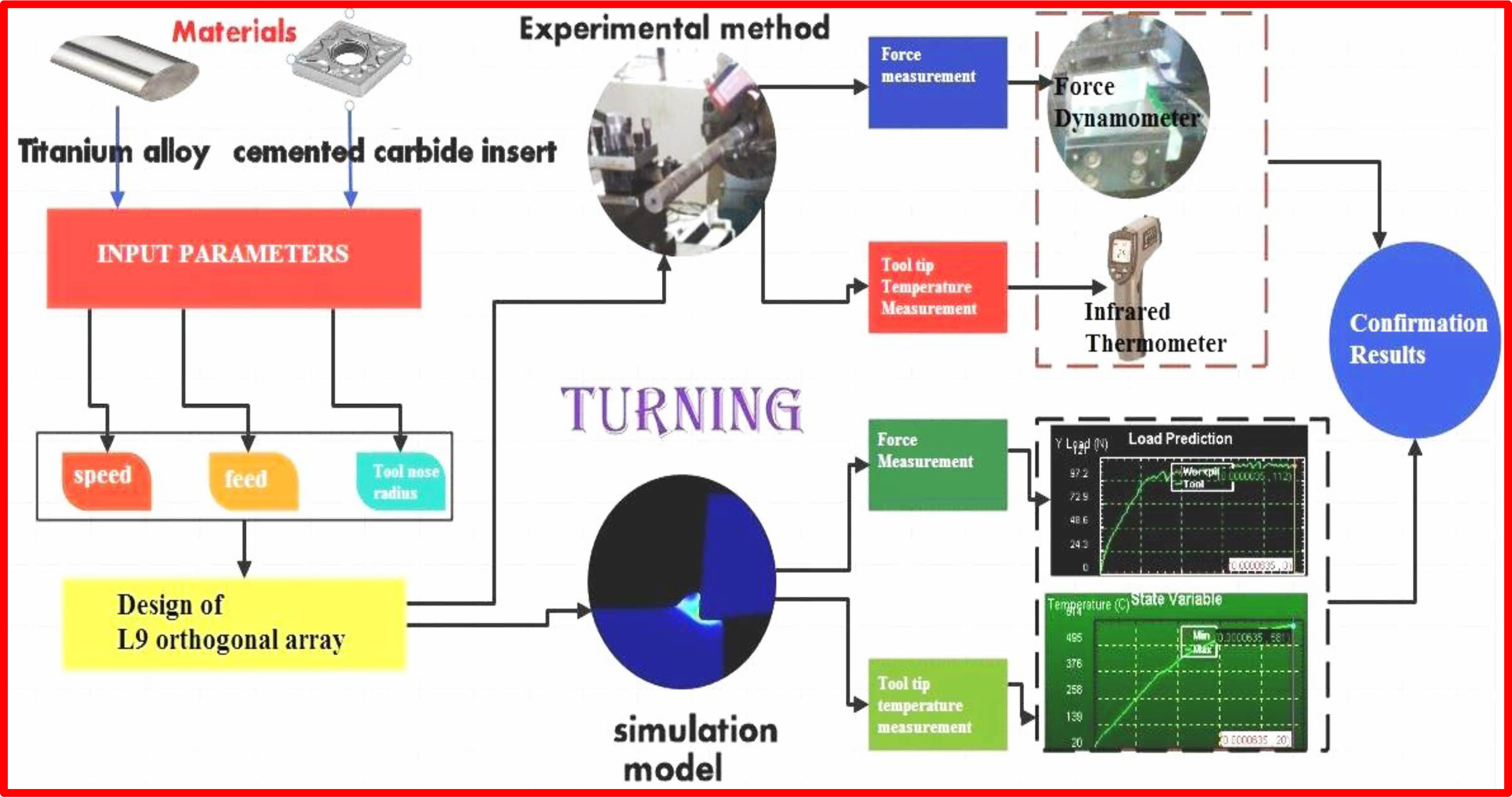
Figure 1 depicts the schematic arrangement of the experimental framework. In this research study, commercially available titanium alloy was preferred as the work material and insert with a clearance angle of 0o, relief angle of 6o, cutting edge length of 15 mm with three distinct nose radii of 0.3 mm, 0.5 mm, and 0.7 mm of uncoated cemented carbide tool was chosen. The chemical composition of the titanium alloy was described in Table 1. Nine tests were carried out using a total of nine cutting tools, three of which had varying nose radii. It was operated with variable cutting speed; feed and constant depth of cut (0.2 mm) were referred from the previous research. In the numerical technique, Deform2D software was effectively employed to simulate the work part, force, wear, and tool tip temperature analysis, and the values were recorded. One of the input parameters related to metal removal conditions is cutting speed and feed, and tool nose radius. The rationale behind choosing tool nose radius is the lack of research work carried out with various parameters. In the experimental approach, all geared lathe with 2 HP motor was employed to accomplish the turning operation. It was intelligently built to integrate infrared thermometers with 2% accuracy and a temperature range of -20 oC to 2200 oC. A Kistler type 9263 make force dynamometer was attached beneath the tool post to record the cutting and thrust force. By utilizing an infrared thermometer, the tool interface temperature was measured at three spots on the perimeter of the workpiece, and the average value was selected. The experimental layout with the levels and the number of stages is listed in Table 2.
|
Fig. 1 schematic layout of the experimental framework. |

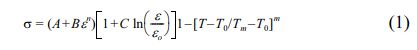
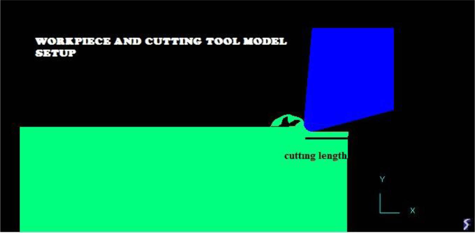
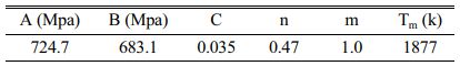
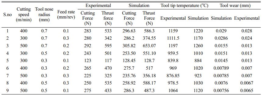
Even though various software packages for analysis are accessible, such as LS-DYNA, ANSYS, ADVANTAGE, ABAQUS, and others, many researchers suggest Deform2D software for its advantages such as rapid computing time and analysis or prediction findings to extremely accurate and nearer to the experimental value. One more benefit of this program is to compute a greater number of mechanical response factors such as damage criteria, force, cutting tool stress, power consumption, effective strain, tool wear depth, wear duration, tool tip temperature, etc. The work model and cutting tool were effectively analyzed in the mechanical behavior or research of the cutting tool and workpiece using deform software. The material of the workpiece was thought to be titanium alloy with plastic behavior, and the tool was assumed to be cemented carbide, which was deemed an elastic material. The selected material for the tool and workpiece acts as the flow stress model and it was expressed with the Johnson-Cook parameter equation, which is easily represented in the equation mentioned in equation (1). In the equation, A and B represented the initial yield strength and hardness modulus, respectively. The Johnson-cook (J-C) parameter value of the titanium alloy was shown in Table 3. In the simulation study, Usui’s wear model was effectively implemented based on the literature studies. The meshing of the workpiece and tool in this numerical research is considered one of the most significant duties to compute the output parameters in a precise manner. Refined mesh approaches precise and accurate values. The adaptive mesh using quadrilateral elements was employed in this study to mesh the workpiece. It was meshed with exactly 1500 elements and 1400 nodes to increase the level of precision in computing output parameters. The cutting tool was meshed using 1000 elements and 900 nodes. The simulation method was clearly shown in Fig. 2. The boundary constraint for the workpiece was configured as fixed in the Y-direction. The ambient temperature for this research was approximated as 25 oC and the heat transfer coefficient was fixed as 20 w/m2 oC. A workpiece modeled with a height of 0.35 mm and a width of 1.5 mm was adopted. The cutting length was assumed to be 15 mm. The cutting speed, feed rate, and tool nose radius for the cutting insert were chosen based on the trial runs, as shown in Table 4. Cutting speed, feed rate, and tool nose radius were varied throughout every run before the simulation. After the end of each simulation run, the output values were computed and are shown in Table 4. It was also integrated with the experimental findings.
|
Fig. 2 Finite element modeling of the work piece and cutting tool. |
Analysis of tooltip interface temperature
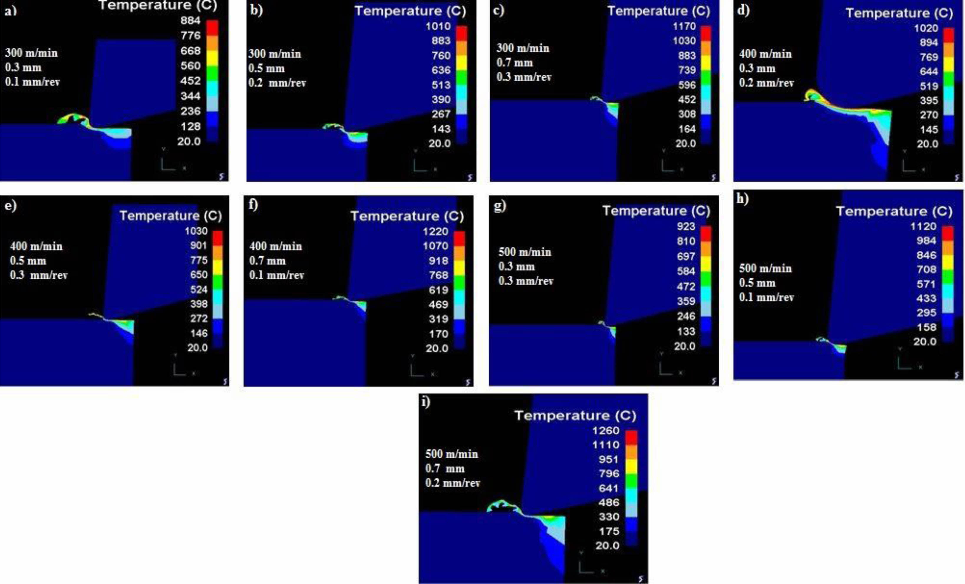
Figure 3(a-i) displays the tooltip contact temperature during the simulated machining of titanium alloy. It was apparent that indicated the maximum temperature happened at the uttermost cutting speed and tool nose radius of 0.7 mm. In both experimental and simulation studies, a maximum temperature of 1260 oC and 1197 oC was reported. Cutting speed and tool nose radius are shown to be quite important in the evaluation of temperature in this temperature investigation. According to the findings, the higher frictional force was created only as a result of the tool nose radius, which was impacted by the maximum interface tool tip temperature. When the tool nose radius is very small, the outcome is a very low minimum temperature. In this investigation likewise, it was proved with a minimum temperature of 839.8 oC, 884 oC was obtained in the 5th experiment [Pop et al.]. The temperature gradually rises as the interplay between cutting speed and tool nose radius. In the case of a reduced nose radius, the gap between the tool and the workpiece was discovered at a minimum temperature. It was also attributed to little surface contact with the interface condition. It was fascinating to see that at the maximum tool radius with varied cutting speeds and feed rates at the highest tool tip contact temperature.
Analysis of cutting tool force
Tool force analysis is one of the most important tasks because tool force is the single key element in making the product related to surface finish.
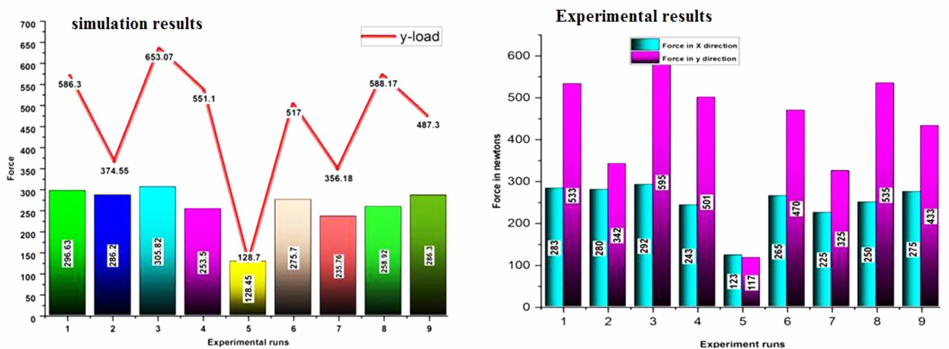
When the tool force is set to maximum, it tends to produce more chattering effects and vibration on the cutting tool, resulting in a poor surface finish. The machining force created parallel to the tool movement in the X-direction is termed the cutting force, and in the perpendicular is referred to as the feed force. In this work, the cutting and feed forces were properly quantified using a force dynamometer. In the simulation, the same was accurately calculated with the assistance of Deform2D software. Fig. 4 demonstrates the graphical depiction of cutting and feed force values. In the simulative and experimental method, the maximum cutting force and feed force were detected on the tool having a bigger nose radius of 0.7 mm. owing to the largest tool nose radius, increasing rubbing action between the tool and workpiece. It was also emulated in the experimental approach. Cutting and feed force were substantially changed from experiment 1 to experiment 5. In the fifth trial, both the forces seem to have the same values with the least force values compared with other values. It’s just because of limited cutting speed and minimal tool nose radius. In agreement with the greatest cutting speed and tool nose radius, an escalation in the tool tip temperature was observed in Table 4 for the 3rd trial. The additional cutting stress was created in the tooltip contact region. At the same time, cutting resistance was minimal due to the reduced nose radius of 0.3 mm, which was selected to minimize nearly 80% of cutting forces.
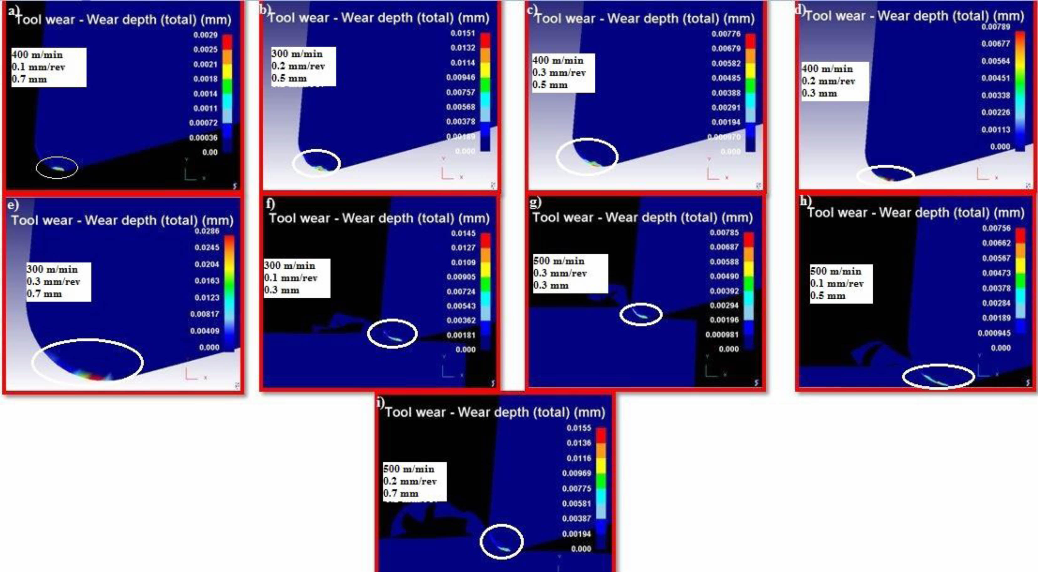
Analysis of tool wear
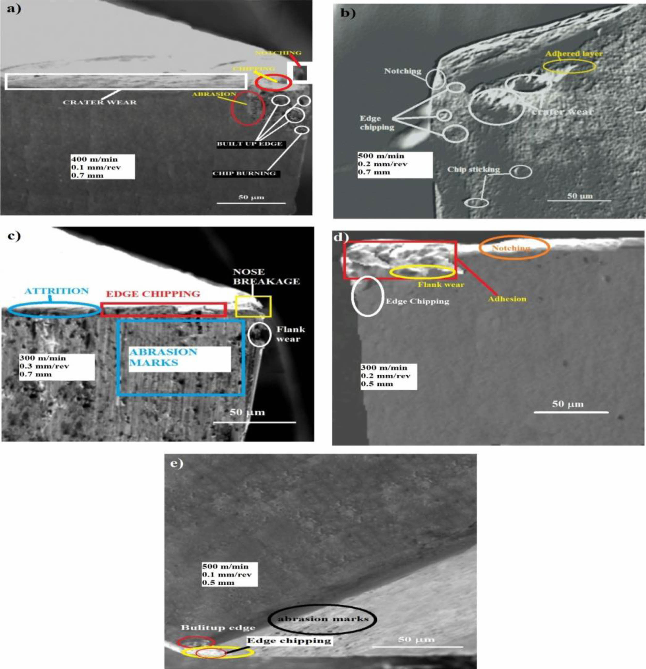
The surface quality of the workpiece is primarily determined by the cutting tool's performance. It is primarily determined by the cutting speed, feed rate, and cutting tool nose radius. The surface quality and achievement of a superior surface finish on the workpiece are improved when these parameters are in optimal condition. Fig. 5(a-i) in this study demonstrates the wear depth on the cutting tool during machining with varying input variables. It was mentioned that the tool nose is primarily affected and influenced by varied wear patterns. Experiment 1 ascertained the maximum tool wear depth. Tool wear depth was determined to be 0.029 mm in simulation and 0.028 mm in the experimental technique due to the maximum tool nose radius and cutting speed. To quantify the cutting tool wear on the tool, an optical microscope was used experimentally. The cutting tool experienced various wear patterns with a cutting speed of 400 m/min, a feed rate of 0.1 mm/rev, and a cutting tool nose radius of 0.7mm, as shown in Fig. 6(a). It was primarily due to the fast cutting speed. The delaminated layer developed an intense abrasive action between the tool and the workpiece [22]. The temperature was reasonably high at this stage, with 1159 oC in experimental conditions. High pressure from elevated cutting forces is also regarded as the primary cause of groove formation in the tool region. It was also demonstrated by the cutting force results in Table 4. Its maximum thrust force was determined to be 586.3 N [26]. A built-up edge was also noticed in certain spots as a result of chip burning. Following that, at the maximum feed rate and cutting tool nose radius of 0.7 mm, the maximum tool wear of 0.0286 was discovered. It was demonstrated in Fig. 6 (b). with various wear patterns derived from a thorough investigation of tool-worn morphology. Edge chipping was visible in some areas, and an adhered layer was also discovered. Chip sticking occurred as a result of the maximum feed rate, as seen in the SEM image. Notching was found laying the tool nose as a result of the chip sticking. Due to high temperatures, crater wear was detected at the tool nose [27]. It was most likely consistent with the simulated findings shown in Table 4. As the feed rate increased, flank wear substantially damaged the tool's flank [24]. It was visible in Fig. 6(c). Edge chipping was the predominant wear found on the cutting edge due to the highest cutting speed, feed rate, and higher tool nose radius. The abrasive markings on the tool surface produced by the chips removed during the machining operation across the surface were visible in the SEM picture.
The flank wear, edge chipping, and adhesive wear were developed due to the high cutting speed and feed rate observed in Fig. 6(d). Abrasive markings, edge chipping, and built-up edges were seen on a few of the spots. When compared to other SEM images, Fig. 6(e) clearly showed that the minimum feed and cutting tool nose radius wear pattern did not affect the tool surface. Wear depth was shown to be very negligible in agreement with these input values, at 0.00756 mm in simulation and 0.006 mm in the experimental technique.
The 2D finite element model was found to be accurate in predicting machining parameters compared to experimental results. The study found that the model was able to effectively predict output parameters and that the tool tip temperature measurement had an average error rate of 5%. The cutting speed was also found to be a major contributor to tool wear and tool forces. The maximum error percentage for measuring tool wear was 14%. The low error percentage of 4% in the measurement of tool force suggests that the numerical investigation was consistent and in good accordance with the experimental investigation.
|
Fig. 3 Simulation results of tooltip interface temperature. |
|
Fig. 4 Graphical representation cutting tool forces |
|
Fig. 5 Simulation results of tool wear. |
|
Fig. 6 Tool wears at different input conditions. |
A numerical model-based simulation with an experimental technique was developed to predict tool forces, tool wear, and tooltip interface temperature while cutting titanium alloy with an uncoated cemented carbide insert. The Deform2D software was convincingly used to create a prediction tool for the current investigation. The observation made on the simulation values is much more accurate and in excellent agreement with the experimental results. The current study highlights the following major findings:
• A 2D finite element model was built to predict machining parameters.
• In this study, experimental modeling combined with a 2D finite element model was used to effectively predict the output parameters.
• In all of these settings, both computational and experimental techniques, nose radius is critical, and it was linearly modeled as temperature, cutting force, and tool wears increased.
• Both in modeling and experimental studies, it was shown that the tool tip temperature measurement had an average error rate of 5%.
• Aside from the tool nose radius, cutting speed was shown to be a major contributor to tool wear and tool forces.
• Due to the tool nose radius being examined, abrasive marks were essentially discovered in all forms of wear patterns.
• Comparing simulated and experimental approaches for measuring tool wear, a maximum error percentage of 14 was reported.
• The development of notches and edge chipping was mostly seen in the cutting tool, which has a maximum tool nose radius. This was investigated using wear depth measurement.
• In a comparison of machining with a tool nose radius of 0.3 mm to 0.7 mm, tool tip temperature was significantly impacted and increased by 30%.
• The low error percentage of 4% in the measurement of tool force suggests that the numerical investigation was consistent and in good accordance with the experimental investigation.
• The analytical and experimental data gained from this work will be highly useful in the future for analyzing the impact, vibration, and damping effects of the related material.
No participation of humans takes place in this implementation process
No violation of Human and Animal Rights is involved.
No funding is involved in this work.
Conflict of Interest is not applicable in this work.
There is no authorship contribution
There is no acknowledgment involved in this work.
- 1. Z.A.M. Tagiuri, T.M. Dao, A.M. Samuel, and V. Songmene, Mater. 15[9] (2022) 3369-3376.
-

- 2. A.B. PoP, A.V. SAndu, A. SAchel Arie, and A.M. ȚîȚu, Arch. Metall. Mater. 67[2] (2022) 120-126.
- 3. A.B. Pop and A.M. Țîţu, IOP Conf. Mater. Sci. Eng. 1235[1] (2022) 2019-2026.
-
- 4. C. Cappellini and A. Abeni, Int. J. Adv. Manuf. Technol. 120[3] (2022) 2055-2073.
-
- 5. K. Zhuang, M. Li, F. Lin, C. Hu, J. Weng, Z. Gao, and C. Wu, Int. J. Adv. Manuf. Technol. 121 (2022) 6763-6781.
-
- 6. I.P. Okokpujie, C.T. Akujieze, J.E. Sinebe, L.K. Tartibu, A. Adeoye, S.E. Kelechi, and E. Akinlabi, J. Adv. Res. Fluid Mech. 97[2] (2022) 8-25.
-
- 7. M.A. Sofuoğlu, F.H. Çakır, S. Gürgen, S. Orak, and M.C. Kuşhan, J. Braz. Soc. Mech. Sci. Eng. 40[3] (2018) 1-12.
-
- 8. G. Shi and H. Zhang, UPB Sci. Bull., Series D. 80[3] (2018) 1-10.
- 9. A.K. Parida and K. Maity, Measurement. 133 (2019) 361- 369.
-
- 10. M.A. Sofuoğlu, M.C. Kuşhan, and O.R.A.K. Sezan, J. Adv. Manuf. Eng. 2[2] (2021) 33-41.
-
- 11. M. Lotfi, and S. Amini, P I MECH ENG E-J PRO. 232[4] (2018) 438-448.
-
- 12. J. Airao and C.K. Nirala, Procedia CIRP. 102 (2021) 61- 66.
-
- 13. K. Leksycki, E. Feldshtein, J. Lisowicz, R. Chudy, and R. Mrugalski, Metals. 10[9] (2020) 1187.
-
- 14. J. Zhou, J. Ren, and Y. Jiang, Proc. Inst. Mech. Eng., Part B. 234[3] (2020) 584-599.
-
- 15. E. Kaya and I. Kaya, Euro. J. Sci. Technol. [14] (2018) 164-168.
-
- 16. F. Çakır, S.E.L.İ.M. Gürgen, M.E.H.M.E.T. Sofuoğlu, M.E.L.İ.H. Kuşhan, and S. Orak, Euro. J. Eng. Natural Sci. 3[2] (2019) 300-306.
- 17. B. Shi, E. Abboud, M.H. Attia, and V. Thomson, Procedia CIRP. 108 (2022) 424-429.
-
- 18. B. Denkena, A. Krödel, and A. Heckemeyer, CIRP J. Manuf. Sci. Technol. 35 (2021) 494-501.
-
- 19. H. Xu, H. Zhou, Z. Ma, L. Dai, X. Jing, G. Li, and Y. Sun, Mater. 12[19] (2019) 3096-3100.
-
- 20. B.S. Sahib and K.S. Nassrullah, IOP Conf. Mater. Sci. Eng. 671[1] (2020) 1100-1105.
-
- 21. C.S. Kumar and S.K. Patel, Surf. Coat. Technol. 309 (2017) 266-281.
-
- 22. V. Sivalingam, Z. Zan, J. Sun, B. Selvam, M.K. Gupta, M. Jamil, and M. Mia, Tribol. Int. 148 (2020) 106-111.
-
- 23. V. Sivalingam, Y. Zhao, R. Thulasiram, J. Sun, and T. Nagamalai, Measurement. 174 (2021) 109-118.
-
- 24. D. Pritima, G. Veerappan, L.M. Azaath, and M. Ravichandran, Surf. Topogr. Metrol. Prop. 10[2] (2022) 250-257.
-
- 25. C.S. Kumar and S.K. Patel, J. Manuf. Process. 31 (2018) 336-347.
-
- 26. V.N. Gaitonde, S.R. Karnik, L. Figueira, and J.P. Davim, Mater. Manuf. Process. 24[12] (2009) 1373-1382.
-
- 27. S. Tooptong, D. Nguyen, K.H. Park, and P. Kwon, Wear 484 (2021) 203982.
-
- 28. K. Aslantas, I. Ucun, and A. Cicek, Wear 274 (2012) 442- 451.
-
- 29. A. Polishetty, M. Goldberg, G. Littlefair, M. Puttaraju, P. Patil, and A. Kalra, Procedia Eng. 97 (2014) 357-364.
-
- 30. L.M. Azaath, E. Mohan, and U. Natarajan, Mater. Today: Proc. 37 (2021) 3731-3736.
-
- 31. L.M. Azaath and U. Natarajan, Int. J. Mater. Res. 112[6] (2021) 486-497.
-
- 32. J. Ren, J. Cai, J. Zhou, K. Shi, and X. Li, Int. J. Adv. Manuf. Technol. 97[9] (2018) 3671-3682.
-
- 33. Seenivasan Murugesan, Venugopal Thangamuthu, Rohokale Milind Shivaji and Suresh Kumar, J. Ceram. Process. Res. 23[3] (2022) 367-372.
-
- 34. T. Tamilanban, T.S. Ravikumar, C. Gopinath, and S. Senthilrajan, J. Ceram, Process. Res. 22[6] (2021) 629-635.
-
- 35. K.M. Senthilkumar, A. Sivakumar, R.M. Shivaji, S.K. Tamang, and M. Giriraj, J. Ceram. Process. Res. 23[2] (2022) 233-236.
-
 This Article
-
2023; 24(3): 461-470
Published on Jun 30, 2023
- 10.36410/jcpr.2023.24.3.461
- Received on Dec 23, 2022
- Revised on Jan 28, 2023
- Accepted on Feb 14, 2023
Services
- Abstract
introduction
literature survey
methodology
finite element modeling
results and discussion
conclusion
- Ethics Approval and Consent to Participate
- Human and Animal Rights
- Funding
- Conflict of Interest
- Author Contributions
- Acknowledgements
- References
- Full Text PDF
Shared
Correspondence to
- D. Ananda Kumar
-
Department of Mechanical Engineering, JCT College of Engineering and Technology, Pichanur, Coimbatore, Tamilnadu, 641105, India
Tel : +91 9787331840 - E-mail: ananddesingh@gmail.com
Clean-Energy Research Institute(CRI), Hanyang University, 222, Wangsimni-ro, Seongdong-gu, Seoul, 04763, Korea
E-mail: jcpr@hanyang.ac.kr