


- Experimental investigation and machinability behavior on synthesized titanium composite
R. Vinothkumara,*, J. Manirajb and V.S. Thangarasuc
aDepartment of Mechanical Engineering, Nehru Institute of Engineering and Technology, Coimbatore, Tamilnadu 641105, India
bDepartment of Mechanical Engineering, Kalaignar Karunanidhi Institute of Technology, Coimbatore, Tamilnadu 641402, India
cDepartment of Mechanical Engineering, Indra Ganesan College of Engineering, Tiruchirappalli, Tamilnadu 620012, IndiaThis article is an open access article distributed under the terms of the Creative Commons Attribution Non-Commercial License (http://creativecommons.org/licenses/by-nc/4.0) which permits unrestricted non-commercial use, distribution, and reproduction in any medium, provided the original work is properly cited.
The current study aims to describe the experimental examination and ultrasonic machinability behavior of the titanium composite, which is synthesized by a casting technique. Tungsten carbide (WC) works as reinforcing particles and adds 6% of the titanium alloy's weight. Material properties, characterization, and alloy composition are examined by mechanical testing, scanning electron microscopy (SEM), and energy dispersive x-ray analysis (EDAX), respectively. Rate of metal removal (RMR) and surface finish (SF) are evaluated by the variation of ultrasonic machining (USM) input constraints such as power rating, slurry concentration, and grit size. Ultrasonic machining parameters and desired responses are optimized using the Taguchi technique. The ultrasonically machined surface and its microstructural analysis are investigated using atomic force microscopy (AFM). The desirable RMR was attained at a power rating of 450 W, a 20% slurry concentration, and a grit size of 400. Surface finish was reached at a power rating of 150 W, 15% slurry concentration, and grit size of 400
Keywords: Titanium composite, Tungsten carbide, Rate of metal removal, Ultrasonic machining, Atomic force microscopy
Titanium alloy has excellent material properties such as formability, corrosion resistance, and high impact toughness. It is utilized in automobile components, aircraft structural, medical, and marine sectors. Metal removal processes rely on the amplitude of vibration and abrasive concentration. The USM input limitations have enhanced the machining quality characteristics [1]. Controlling the cutting force using ultrasonic vibrations improved the rate of metal removal and surface quality of the machined surface [2, 3]. The rate of metal removal and surface roughness were significantly impacted by vibration and tool feed. Microscopic examination was used to investigate the surface topography of the machined surface [4]. By using several unconventional machining techniques, the machinability properties of titanium and its alloy were studied. The ultrasonic vibrations affected the roughness of the surface [5]. The vibrations generated by the USM transducer determine the tool feed, which has the most impact on the circularity of the holes [6]. The developed model was utilized to predict cutting force and feed. The minimum surface roughness was achieved at lower feed rate [7]. Taguchi optimization was used to improve ultrasonic machining performance and attain the desirable characteristics of the response parameters [8].
This research work is dealing with the ultra sonic machining of synthesized titanium composite and its response factors are optimized by Taguchi approach. The machined surface and its micro structural analysis are investigated by SEM and AFM images.
Material
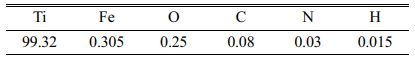
A titanium metal matrix composite reinforced with 6% tungsten carbide was fabricated using 99% pure titanium as the base material. Titanium has excellent mechanical strength, machinability, and corrosion resistance. Tungsten carbide was used as a reinforced material, and its size was roughly 40 microns. The chemical composition of the titanium was presented in Table 1.
Methods
Stir casting is the best process to make titanium metal matrix composites enhanced with tungsten carbide particles. Stirrer speed, temperature and composition of alloying elements are affected the fabrication of material. Titanium was heated over 1700 oC owing to its high melting point. Reinforced particles were preheated and added to the molten titanium alloy. The stirrer was run at 250 rpm for 6 minutes to create a homogenous mixture of titanium with reinforced WC particles.
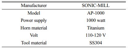
Particle size of the WC is 150 microns. Consequently, homogeneous dispersion of particles across the composite was accomplished. After the end of the casting process, as per the ASTM standard, nine samples were made with the dimensions of 10 mm × 10 mm and 55 mm in length. The second part explicates the experimental work carried out by employing an ultrasonic vibration-assisted milling machine. Ultrasonic machining is one of the subtractive manufacturing methods, where the material is removed from the component by high-frequency, low-amplitude vibrations in the presence of small abrasive particles. The ultrasonic mill runs at a frequency of 20 kHz and amplitude of 25 microns. A boron carbide abrasive particle with a grain diameter of 34 µm was utilized. At room temperature, 60 grams of abrasive particles were added to one litre of water (the slurry medium). Slurry concentration, feed rate and power rating are the factors to affect the machining rate. A stainless steel 304 stepped tool brazed with silver was considered. The details of USM are shown in Table 2.
The material is removed by impact erosion. The metal eroded from the work piece by the combination of tool vibration and abrasive slurry. Slots have been created over the composite in this technique using a milling cutter with a diameter of 5 mm. The machining dimension of 30 mm in length, 5 mm in slot width, and 0.5 mm in cut depth was taken into consideration. An ultrasonic vibrator was fixed to that machine to create vibrating action against the work piece, and at the same time, the abrasive action of slurry particles began to remove the material in a continual way. Power rating, slurry concentration, and grit size are termed the input factors.
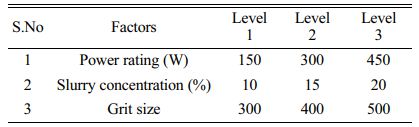
Three levels have been utilized, and the values are given in Table 3. The rate of material removal and surface finish is the output of this study. The output findings are reported in Table 4.
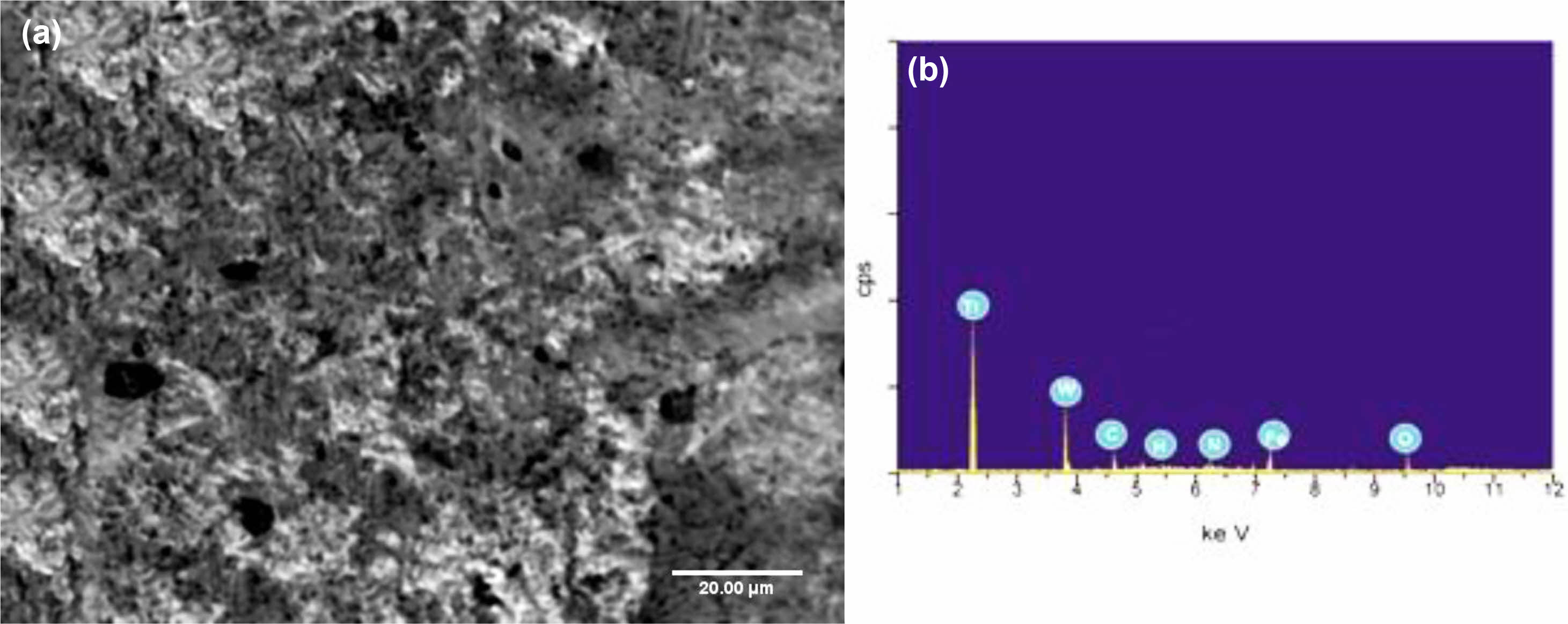
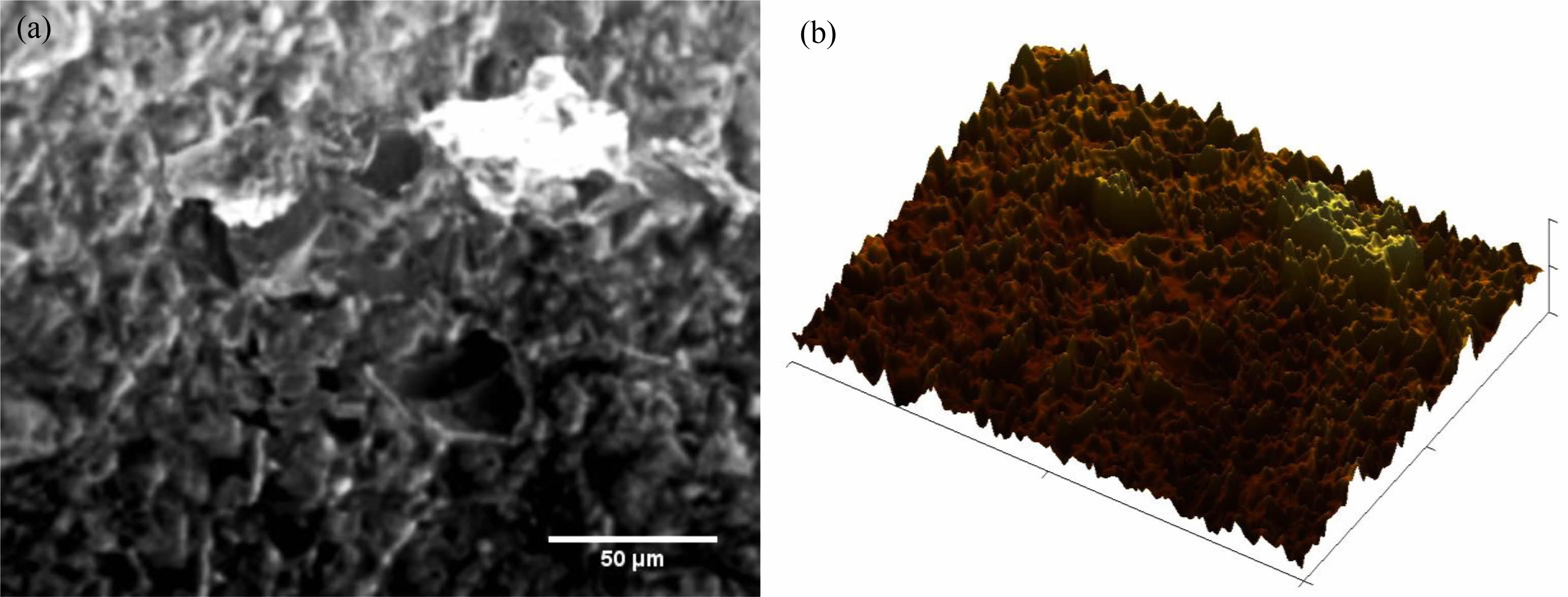
A neatly illustrated SEM image of the fabricated Ti-5%WC composite is presented in Fig. 1(a). The tungsten carbide particles were plainly visible encrusted on the surface. EDAX analysis of the composite is given in Fig. 1(b). It demonstrates that titanium is the most essential element with a high peak. Also verified was the existence of tungsten, carbon, and iron components, which had the least amount of contribution evident with a modest peak profile.
Titanium-based metal matrix composites are particularly difficult to machine using traditional machining processes owing to their high hardness. For machining Ti-6%WC composites, innovative machining procedures like as ultrasonic vibration aided milling were utilized. Micro milling processes were carried out for nine samples utilizing USM. The milling process requires three distinct levels of input variables. Power rating, slurry concentration, and grit size were regarded the input factors. For estimating optimal parameters, an experimental order was built using a L9 orthogonal array [21]. The USM type AP-1000 was utilized in this machining operation. The power supply of this machine was stated at 1000 watts.Titanium and SS304 are utilized as horn and tool materials, respectively. High-pulsed electrical energy is turned into vibrating or oscillating energy in the tool holder. Horn is used to transfer the vibrations from transude to the work piece. On the workpiece, the vibrating action is paired with the abrasive action of slurry particles. Slot milling was carried out on each sample. At the end of each step, the rates of material removal and surface finish were determined. The rate of material removal was assessed by estimating the change in weight before and after the machining operation per minute. A digital weigh machine was utilized to accurately measure the weight of the material. Surface finish was calculated at 3 unique spots across the surface, and the average value was reported by utilizing a surf tester. Measuring range of the tester is 0.05 to 10 µm. Cut off length is 0.8 mm and measuring length is 1.25 mm.
|
Fig. 1 (a) SEM image of Titanium with reinforced tungsten carbide particles, (b) EDAX analysis. |
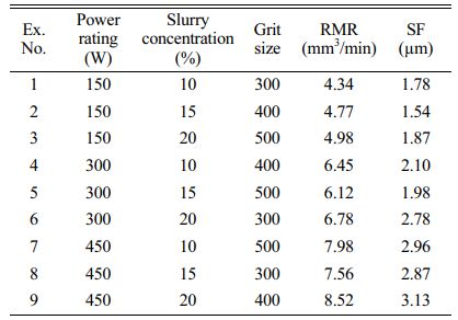
The experimental outcomes of the USM are mentioned in the Table 4. The rate of metal removal and surface finish observations were recorded by the combined effect of abrasive slurry and mechanical vibrations. The rate of metal removal was steadily increased by the increase of input constrains. Experimental design was followed by L9 orthogonal array.
Optimization method for RMR
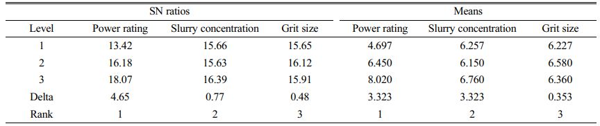
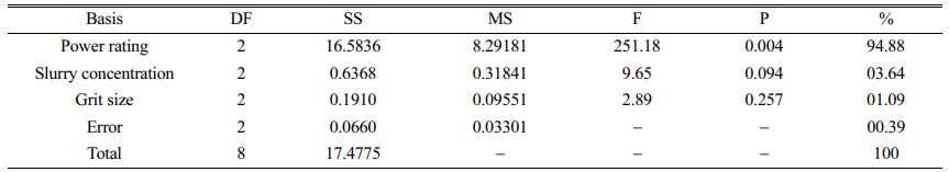
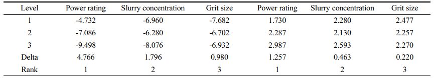
The experimental research of the rate of metal removal from titanium composite was planned as per the L9 orthogonal array. To attain a higher rate of metal removal, a larger the better criteria was selected. The signal-to-noise ratio (SN) and means were determined as per criteria. The input variables such as power rating, slurry concentration, and grit size and their levels are indicated in Table 5.
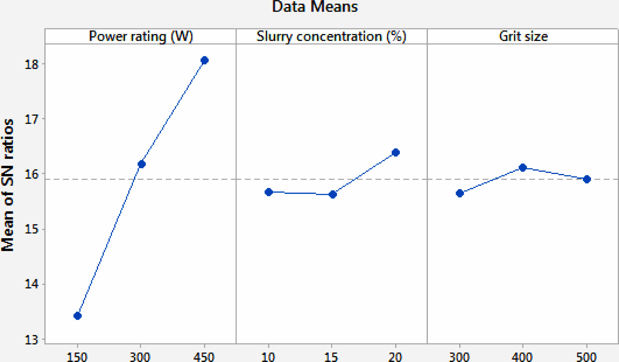
Fig. 2 demonstrates the influence of the SN ratio on the surface polish of titanium composite. As per the goal of the experimental investigation, it was at the minimum level. The optimum RMR was achieved at 150 W of power rating, 15% of slurry concentration, and a grit size of 300. The optimal factor level of A1B2C1 was selected for ultrasonic machining of titanium composites. Table 6 demonstrates the influence and involvement of each factor on the rate of metal removal. The impacts of power rating, slurry concentration, and grit size are 94.88%, 3.64%, and 1.09%, respectively.
Optimization method for SF
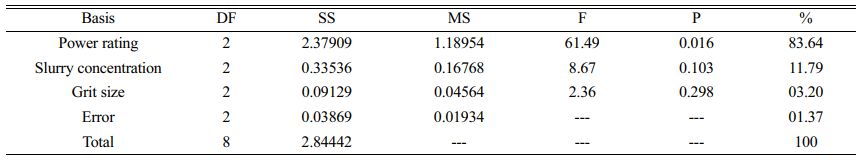
According to the L9 orthogonal array, the experimental investigation of the rate of metal removal from titanium composite was proposed. Larger the better criteria was adopted to attain a high amount of metal removal. Lower the better criterion was applied for SR in taguchi approach. The signal-to-noise ratio (SN) and means were determined as per criteria. The input variables such as power rating, slurry concentration, and grit size and their levels are presented in Table 7.
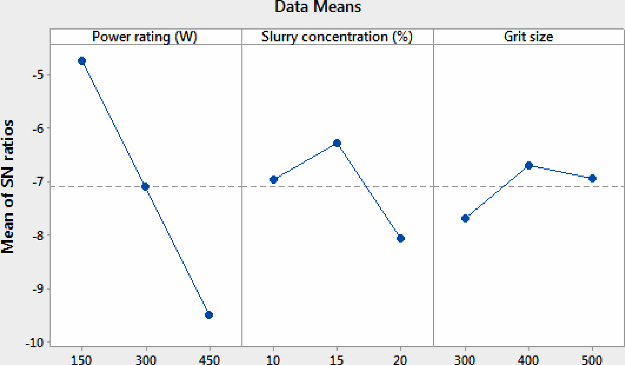
Fig. 3 demonstrates the influence of the SN ratio on the surface finish of titanium composite. The rate of metal removal was at its highest, which was the purpose of the experimental investigation. The optimum RMR was performed at 450 W of power rating, 15% slurry concentration, and a grit size of 400. The optimal factor level of A1B2C2 was selected for ultrasonic machining of titanium composites. Table 8 indicates the influence and importance of each component on the rate of metal removal. The impacts of power rating, slurry concentration, and grit size are 83.64%, 11.79%, and 3.20%, respectively. Power rating was the dominant factor in RMR and SR.
|
Fig. 2 SN ratio effect for titanium composite -RMR. |
|
Fig. 3 SN ratio effect for titanium composite-SF |
The most important work was microstructural characterization of the machined part to assess defects and evaluate the impacts of power rating, slurry concentration, and grit size during ultrasonic machining.
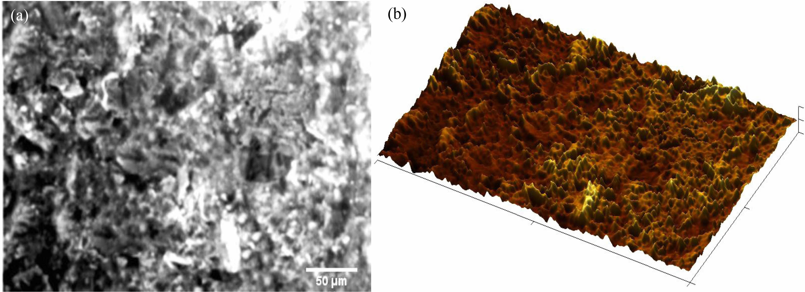
Fig. 4(a) depicts the SEM image of the milled specimen of titanium reinforced with 6% tungsten carbide particles. The milling operation was carried out on the USM with a power rating of 300, a slurry concentration of 15%, and a grit size of 500 as the input variables. Fig. 4(b) depicts the atomic force microscopic image of the related SEM image. In this work, AFM is largely focused on visualizing the surface of the milled surface. The AFM image displayed a surface structure comprised of peak and valley features. Due to their greater power rating and maximum slurry concentration, abrasive particles increase the material removal rate and affect the surface finish. It was plainly evident in the SEM image, which has a sharp edge extremely near to the surface's deeper grooves.A larger chunk was also observed in the image. It demonstrates that more material was removed, as indicated by Fig. 4(b), which displays a collection of highlighted peak profiles. The propagation of cracks originates and creates deeper grooves on the surface. It was largely because of the aggressive action of abrasive particles impacting against the work material owing to the vibrating action of the tool holder. Deeper grooves deteriorate the surface, as shown by the roughness values [9]. Deeper grooves imply the rate of material removal looks high owing to the highest slurry concentration [10]. The ductile mode area revealed in the SEM image suggests the smooth region was improved owing to the abrasive effect of small particles during the ultrasonic machine-assisted milling process [11]. It was also established that the small abrasive particles increase the surface finish of the specimen in specific distinct spots. Fig. 4(b) displays a lesser number of spike profiles because of the bulky particles that have grown owing to granular fractures. The valley profile in the AFM image was generated in several locations on the surface, suggesting the growth of deeper grooves. Bulky materials developed as slurry concentration rose, resulting in a poor surface finish [12].
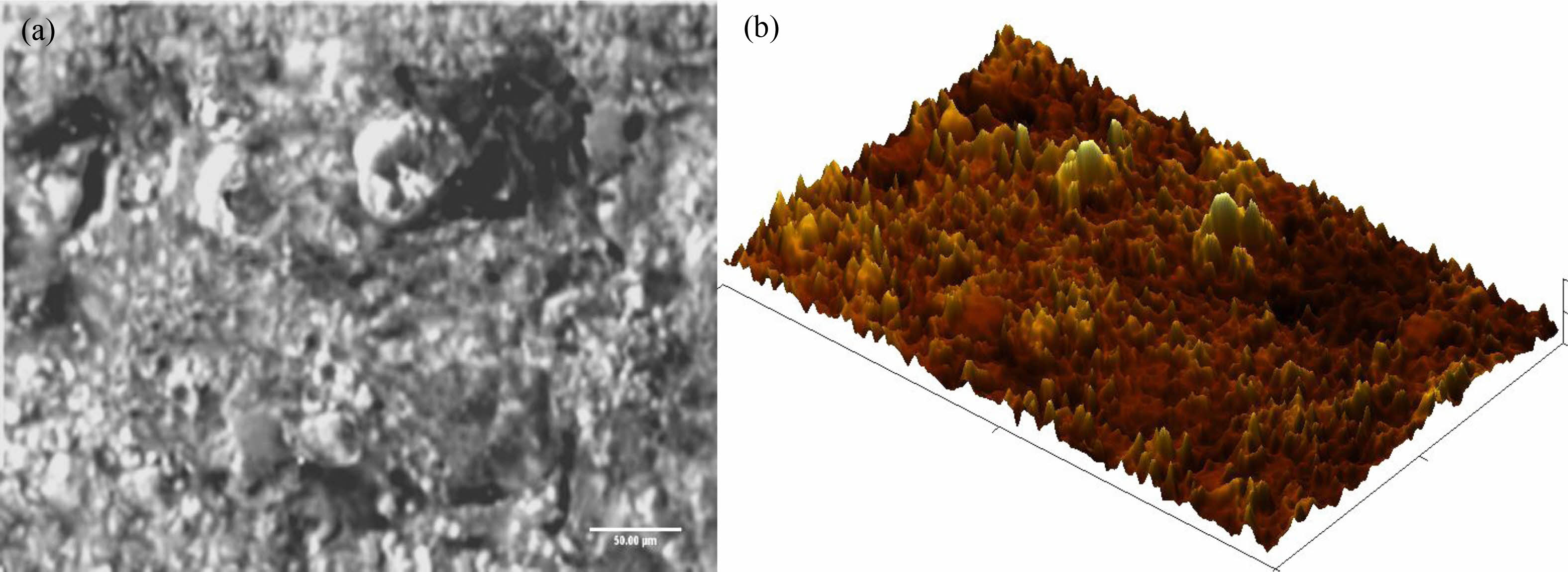
Fig. 5(a) displays the SEM image of the sample being machined at a power rating of 450, a slurry concentration of 10%, and with the aid of abrasive particles with a grit size of 300. Fig. 5(b) shows the AFM image of the comparable SEM image. In the SEM image, micro cracks were scattered throughout the surface and detected in the figure. It was owing to the maximum power rating in the milling process. A hammering effect occurs in the USM process as a result of vibration, which generates microcracks and voids on the surface. A sharp edge formation was also noticed. A larger quantity of material removal causes the sharp edge creation and exacerbates the fragility attribute of the material, which deteriorates the surface. Due to cyclic stress, a crack extends across the surface and generates the sharp edge portions [13]. Sharp edges were developed due to the effect of reinforced particles presence in the materials [14]. The built-up edge was seen in the image and was corroborated by the AFM image. The greatest power rating was found to have the maximum material removal rate; it initiates coarse surface erosion, resulting in shear fracture on the machined surface [15]. A built-up edge extruded across the surface with a high spike profile, as clearly visible in Fig. 5(b). These kinds of occurrences were noticed in Fig. 5(a). The pulling of grains was also noticed. Pulling of grains occurs as a consequence of the severe indentation of abrasive particles. which was encircled in Fig. 5(a). A cavity profile was identified in Fig. 5(b) owing to a shear fracture that was detected. Plastic deformation was also seen in some spots.
Fig. 6(a) depicts the SEM image of the machined samples under the experimental setting with a power rating of 450, a slurry concentration of 20%, and a grit size of 400. This experimental condition pertains to the ninth experiment. From the data reported in Table 4, a maximum rate of material removal of 8.52 mm3/min and a worse surface finish value of 3.13 microns were reached at this experimental condition. Based upon the findings, it was recommended that only RMR be subjected to maximum function. However, it proved unsuitable for the other response variable of surface finish. The SEM image was clearly displayed in Fig. 6(a). It was clearly seen that due to the maximum power rating and modest ultrasonic frequency, the vibration was formed on the tool that hammered on the work surface. The hammering action is responsible for the creation of surface fractures [16]. The hammering impact also resulted in the development of the cavity profile, which is clearly seen in Fig. 6(b). AFM displays the valley profile created by the detected cavity. It was extremely evident that the power rating contributed significantly to the rate of material removal in USM [17]. It was proven with this investigation that the power rating contribution % is around 94.8, as stated in Table 6. Grain pull-off also takes happen in certain areas. Slurry concentration was also regarded the most essential element in enhancing the rate of material removal. The abrasive particles provided greater abrasive action as the slurry concentration rose, resulting in more material removal [18]. As a consequence, vibration is significant in USM for material removal rate. The vibration of a tool delivers kinetic energy to the work surface by way of impact. Abrasive particles participating in this machining process release this energy over the surface, which results in plastic deformation [19]. And also owing to the continual impact of the hammering action, a plastically deformed zone was developed. A greater power rating increases the RMR as well as the plastic deformation on the surface. Not only this, but raising the tool temperature leads in plastic deformation [20-21]. The rate of metal removal and surface texture is related to the properties of the materials and level of machining input constrains of the process [22-24]. Adhesion of the titanium matrix was found in the SEM image indicated in Fig. 6(a). Grain pull-off also took place, and it was extruded from the surface, as was clearly noticed in the AFM image. The maximum material removal rate was identified in the ninth experiment, which is primarily determined by the maximum power rating and slurry concentration. Metal was bonded together, and binding of material was detected owing to the long duration of machining time. It was clearly demonstrated in Fig. 6(b), and it was validated by the peak profile across the surface as seen in AFM. Tungsten carbide particles were plainly observed embedded across the specimen.
|
Fig. 4 SEM image of the machined titanium composite at the experiment run 5. (a) SEM image, (b) AFM image. |
|
Fig. 5 SEM image of the machined titanium composite at the experiment run 7. (a) SEM image, (b) AFM image. |
|
Fig. 6 SEM image of the machined titanium composite at the experiment run 9. (a) SEM image, (b) AFM image. |
In the current research study carried out on the experimental investigation and machinability behavior of synthesized titanium metal matrix, the outcomes that were achieved after the experimental study:
• A tungsten carbide based titanium metal matrix was fabricated by the stir casting process.
• The machining parameters of the USM process and its optimal response value were reached by Taguchi optimization.
• The best values of A1B2C1 for the maximization of RMR and A1B2C2 for the minimization of surface finish were determined by Taguchi analysis.
• The most influential parameter is the power rating, with a contribution percentage larger than 83% for the response variables such as RMR and SF.
• The optimal solution for RMR was reached at a power rating of 450 W, a 20% slurry concentration, and a grit size of 400. Surface finish was reached at a power rating of 150 W, 15% slurry concentration, and grit size of 400.
• Microscopical investigation was successfully done on the machined samples to examine the material behavior following USM.
• Atomic force microscopy study was also carried out to observe the surface parameters in a 3D image.
• Microcracks were typically discovered in all the samples, which induced the deeper groove and shear failure.
• Grain pull-off was seen at its greatest in all the samples owing to the strong impact of tool action during machining.
• Surface finish was enhanced by 43% in the machining process when low power was employed against high power.
• During the USM process, the rate of material removal increased by 50% at high power ratings compared to low power ratings.
No participation of humans takes place in this implementation process
No violation of Human and Animal Rights is involved.
No funding is involved in this work.
Conflict of Interest is not applicable in this work.
There is no authorship contribution
There is no acknowledgement involved in this work.
- 1. H. Zha, P. Feng, and J. Zhang, Int. J. Adv. Manuf. Technol. 97 (2018) 2099-2109.
-

- 2. H. Li, T. Chen, and Z. Duan, J. Mech. Sci. Technol. 36 (2022) 3631-3642.
-
- 3. J. Wang, J. Zhang, and P. Feng, Compos. Pt. B-Eng. 129 (2017) 233-242.
-
- 4. Y. Xu, F. Gao, and P. Zou, J. Mech. Sci. Technol. 34 (2020) 3791-3806.
-
- 5. M.Y. Tsai, C.S. Fang, and M.H. Yen, Int. J. Adv. Manuf. Technol. 97 (2018) 297-304.
-
- 6. S. Das, S. Kumar, B. Doloi, B. Bhattacharyya, J. Adv. Manuf. Technol. 86 (2016) 829-839.
-
- 7. A. Abdelkawy, J. Eng. Appl. Sci. 69 (2022) 50-55.
-
- 8. D. Sindhu, L. Thakur, and P. Chandna, Silicon 11 (2019) 2033-2044.
-
- 9. D. Sindhu, L. Thakur, and P. Chandna, Silicon 12[3] (2020) 629-643.
-
- 10. R.P. Singh, and S. Singhal, Proc. Inst. Mech. Eng. L P I MECH ENG L-J MAT. 232[12] (2018) 967-986.
-
- 11. R.P. Singh and S. Singhal, J. Eng. Res. 6[1] (2018) 60-65.
- 12. T. Hegade, J. RK, L.R. Nagarjuna, P.P. Babu, A.K. Srikanth, and T.S. Nanjundeswaraswamy, Int. J. Eng. Res.Technol. 8[11] (2019) 1-10.
- 13. R.P. Singh, and S. Singhal, Mater. Manuf. 32[3] (2017) 309-326.
-
- 14. J. Wang, K. Shimada, M. Mizutani, and T. Kuriyagawa, Precis. Eng. 51 (2018) 373-387.
-
- 15. H. Zha, P. Feng, J. Zhang, D. Yu, and Z. Wu, Int. J. Adv. Manuf. Technol. 97[5] (2018) 2099-2109.
-
- 16. D. Popli and M. Gupta, Mach. Sci. 22[3] (2018) 427-453.
-
- 17. C. Sivakandhan, G.B. Loganathan, G. Murali, P.S. Prabhu, S. Marichamy, G.S. Krishnan, and R. Pradhan, Mater. Res. Express. 7[1] (2020) 150-156.
-
- 18. B. Stalin, T.V. Vardhan, S. Marichamy, J. Vairamuthu, M. Ravichandran, and V. Dhinakaran, AIP Conf. Proc. 2283[1] (2020) 301-308.
-
- 19. S. Kumar and A. Dvivedi, J. Braz. Soc. Mech. Sci. Eng. 41[10] (2019) 1-16.
-
- 20. M. Kumar and P. Kumar, Optim. Eng. Res. 1[2] (2020) 40-54.
-
- 21. J.H. Biswas, N.A. Jagadish, and A. Ray, Int. J. Mach. Mach. Mater. 21[1-2] (2019) 115-137.
-
- 22. M. Kumar, S.K. Tamanga,Dipika Devi, M. Dabia, K.K. Prasad, and R. Thirumalai, J. Ceram. Process. Res. 23 (2022) 373-382.
-
- 23. R. Srinivasan, B.S. Babu, P. Prathap, R. Whenish, R. Soundararajan, and G. Chandramohan, J. Ceram. Process. Res. 22[1] (2021) 16-24.
-
- 24. M. Kannaiyan, J.G.T Raghuvaran, K. Govindan, and E.P. Annamalai, J. Ceram. Process. Res. 21[1] (2020) 26-34.
-
 This Article
-
2023; 24(3): 453-460
Published on Jun 30, 2023
- 10.36410/jcpr.2023.24.3.453
- Received on Dec 19, 2022
- Revised on Feb 13, 2023
- Accepted on Feb 14, 2023
Services
- Abstract
introduction
experimental method and material
result and discussion
micro structure analysis
conclusion
- Ethics Approval and Consent to Participate
- Human and Animal Rights
- Funding
- Conflict of Interest
- Author Contributions
- Acknowledgements
- References
- Full Text PDF
Shared
Correspondence to
- R. Vinothkumar
-
Department of Mechanical Engineering, Nehru Institute of Engineering and Technology, Coimbatore, Tamilnadu 641105, India
Tel : +919944121507 - E-mail: auvinothmech@gmail.com
Clean-Energy Research Institute(CRI), Hanyang University, 222, Wangsimni-ro, Seongdong-gu, Seoul, 04763, Korea
E-mail: jcpr@hanyang.ac.kr