


- Studies of structural and electrical properties of La-Mg-Mn-Ti-O ceramic
Siti Hashimah bt Mohamad Hanifa, Walter Charles Primusa,*, Khamirul Amin Matorib, Josephine Liew Ying Chyib and Aaliyawani Ezzerin Sinina
aDepartment of Science and Technology, Faculty of Humanities, Management and Science, Universiti Putra Malaysia Bintulu Campus, 97008 Bintulu, Sarawak, Malaysia
bDepartment of Physics, Faculty of Science, Universiti Putra Malaysia, 43400 Serdang, Selangor, MalaysiaThis article is an open access article distributed under the terms of the Creative Commons Attribution Non-Commercial License (http://creativecommons.org/licenses/by-nc/4.0) which permits unrestricted non-commercial use, distribution, and reproduction in any medium, provided the original work is properly cited.
The samples with chemical formula La1-xMgxMn0.4Ti0.6O3 (x = 0.30, 0.40 and 0.50) were synthesized using solid-state reaction method. XRD of the samples shown the samples pattern attributed to the cubic structure with ‘a’ = 3.8943 and its space group Pm3m. The SEM images display microstructure of the sample were porous and the grains are merged with unequal sizes distributed inhomogeously throughout the samples with irregular boundaries. The sample of x = 0.4 was the most porous than the others. The electrical properties were measured using LCR meter with the frequency range from 0.01 Hz until 100 KHz and in a temperature range of 313 K until 373 K. The electrical properties of the samples were study by analyzed the dielectric constant, ε’, dielectric loss, ε”, and tan δ. The results for dielectric constant and dielectric loss showed the higher values were located at lower frequency region which suggest that the samples were having interfacial polarization. Tan δ shows the lower value at higher frequency and lower temperature. By doping Mg, it decreases the dielectric loss and increasing the Mg doping it increases the dielectric constant
Keywords: Mg2+ Doping, Dielectric, Ceramic, Solid state reaction method
Ceramics are well known due to their characteristics such as the ability to prevent corrosion, steady chemically, high melting points, and non-conductors of heat and electricity. Advanced ceramics are mass-produced to be used in electrical components, high-temperature applications, and in body-worn armor [1]. As reported by Das et al, the classification of ceramics is according to their compositions as oxides, carbides, nitrides, and Borides [2]. As one of the most important structural ceramics, Aluminum oxide (Al2O3) is used as an electrical insulator and biocompatible medical devices, as well as applied for technical uses as a result of its high chemical and thermal resistance [3]. To have the robustness and notable refractoriness type of ceramic composite, this requirement can be met using light elements such as Be, B, N, O, Mg and Al because performable ceramics have one or more of the stated elements to be constituents [4, 5] such as MgTiO3. As a microwave dielectric material, Magnesium titanate (MgTiO3) ceramic has a dielectric constant as high as 17, a quality factor value as high as 160 000 GHz, and a resonance frequency temperature coefficient, τf indicating a negative value (-50 × 10–6/oC) [6]. It has been found that MgTiO3 also has low dielectric loss and had been used as dielectric resonators in integrated circuits for wireless networks, global positioning systems, and mobile phones [7]. The crystalline system for pure MgTiO3 is Hexagonal space group R3 and known for the ilmenite structure of MgTiO3 with lattice parameters, a = 5·05 Å and c = 13·86 Å [8-10]. Another Mg base compound, LaTiMgO3 shows low-loss dielectric material and has a distorted cubic structure [11]. From report by Zhao et al., by doping 0.005LaTi0.5Mg0.5O3 to (Bi0.5Na0.5)TiO3.(Sr0.7Bi0.3)TiO3, leads to stable dielectric constant (2170±15%) at high-temperature range of 35-363 oC [12]. From Yang et al., studies, fabrication of La1-xMgxTiO3 by solid state method, shows the composites is preferable for industrial applications as high temperature negative temperature coefficient (NTC) thermistors over a 400-1200 °C [13]. Oxides based on LaMnO3, are well-known for their ferromagnetic behavior as well for their giant-magnetoresistance [14]. It is known too that doped lanthanum manganite materials R1-xAxMnO3 where R is a trivalent rare earth ion and A is a divalent ion are interesting because of its negative colossal magnetoresistance (CMR), magnetic transition, and metal-insulator phase transition [15]. La1-xCax Mn1-yFeyO3 (x=0.37,0.53 y=0.2) was found to have suppression of ferromagnetism and metallic conduction in the compound due to the presence of Fe [16]. Introduction of tetravalent Ti ion at B-site of perovskite manganite, La0.1Ca0.9Mn1-xTixO3 was been investigated affecting the transport properties and was found a weakening of the cation-anion-cation overlapping [17]. Thus, based on literature reviews, we conduct research in order to study the effect of adding Mg to the A-site of LaMnTiO3 material; La1-xMgxMn0.4Ti0.6O3 (x = 0.30, 0.40, and 0.50) and study its structural and electrical properties in temperature of 40 oC until 200 oC. The electrical statistics were analyzed in complex permittivity, and tan δ. It is expected by doping Mg would decrease the dielectric loss and increasing Mg doping would increase the dielectric constant.
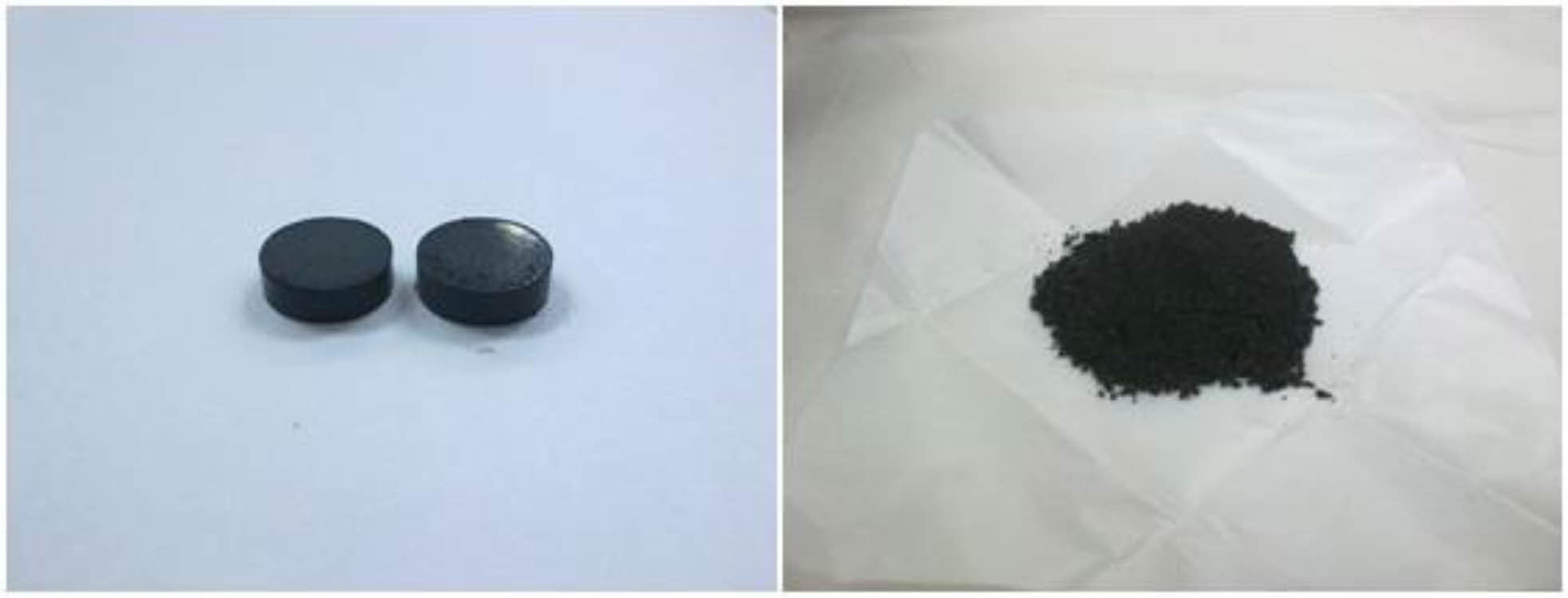
Solid-state reaction method were used with high quality oxide powder; lanthanum oxide, La2O3 (CAS No.: 1312-81-8), magnesium oxide, MgO (CAS No.: 1309-48-4), manganese oxide, MnO2 (CAS No.: 1313-13-9), and titanium oxide, TiO2 (CAS No.: 13463-67-7) to create La1-xMgxMn0.4Ti0.6O3 where composition x = 0.30, 0.40, and 0.50. The samples preparation is following the method in previous preparation of La1-xSrxMn0.4Ti0.6O3 [18, 19] and La0.70Ba0.30Mn0.40Ti0.60O3 [20]. The stoichiometric ratios of the reactant required were weighed accordingly and then mixed with distilled water as their medium for 24 hours. The samples goes for the drying process in 48 hours at temperature of 80 oC and afterward grounded for 30 minutes. The calcination was performed in two stages where first stage of calcination started at 800 oC for 12 hours and the second stage at 1000 oC for 12 hours, before sintered at 1200 oC for 12 hours. Half of the samples were in pellet form and half of it in powder form. Fig. 1 shows what the final sample will look like.
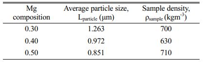
The sample in powder form was used for XRD analysis while the pellet sample was for dielectric measurement. As for SEM analysis, a small fracture of the pellet was used. The characterization analysis for their crystalline phase exist in the sample was carried out using the X-ray powder diffractometer, Phillips PW 3040/60 X’pert Pro (λCu=1.5406 Å) with a scanning angle of 20°-80° at room temperature. As for the surface morphology of the samples has been studied using Scanning Electron Microscope, JEOL JSM-6390. Inductance-capacitance-resistance LCR meter, Hioki 3522-50 LCR HiTESTER was used to measure the electric properties of capacitance (C) and conductance (G) with the frequency range set up from 0.01 Hz until 100 kHz and in a temperature range of 40 oC until 200 oC. The pellet dimension for dielectric analysis is measured by calculation in Equation (1) where εo permittivity free space, A surface area range; (5.62- 7.76) × 10-5 m2 and d thickness range; (0.002-0.003) m of pellet. From the result of the LCR meter, the data then be transformed into permittivity values to find out their electrical properties. To support the SEM analysis, samples density and average particle size of the samples also been studied. The sample density was determined using the Archimedes method. The pellets were submerged into distilled water and the changes in water volumes ∆V, and masses ∆m were recorded. The average particle size was gathered using a linear intercept method and can be seen in Table 2.

|
Fig. 1 Form of samples in pellet and powder. |
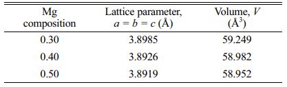
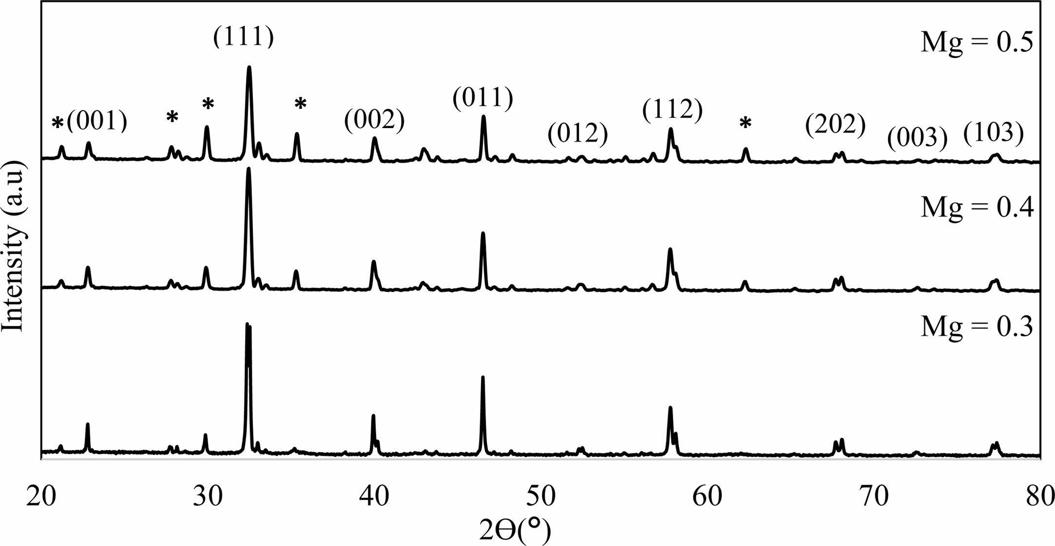
After fabrication of La1-xMgxMn0.4Ti0.6O3 (x = 0.30, 0.40 and 0.50) samples using solid-state method, structural and electrical analysis were performed. X-ray diffraction showed the sample’s lattice structure. From Fig. 2, by using CHECKCELL software, the sample’s crystalline system is in a cubic structure with a space group of Pm3m. The finding of the patterns can be found similar to SrTiO3 [21], (La0.4Ba0.4Ca0.2) Mn0.4Ti0.6O3 [22], and LaxSr1-xTiO3 (x = 0.0-0.4) [23]. There is the existence of a few peaks from the presence of reactants which is the existence of La2Ti2O7 [24]. The second phase increases as the Mg content increase. The values of lattice parameter and structure volume were tabulated in Table 1. The lattice parameter, a=b=c decreases as the Mg content increase and this shows that there is the rearrangement of the atoms in the lattices [24]. The same goes to its unit cell volume to decrease as the Mg content increase due to the replacement of the small size of Mg2+ ions (72 pm) [25] by larger size La3+ ions (103.2 pm) at the A-site of the sample structure [23].
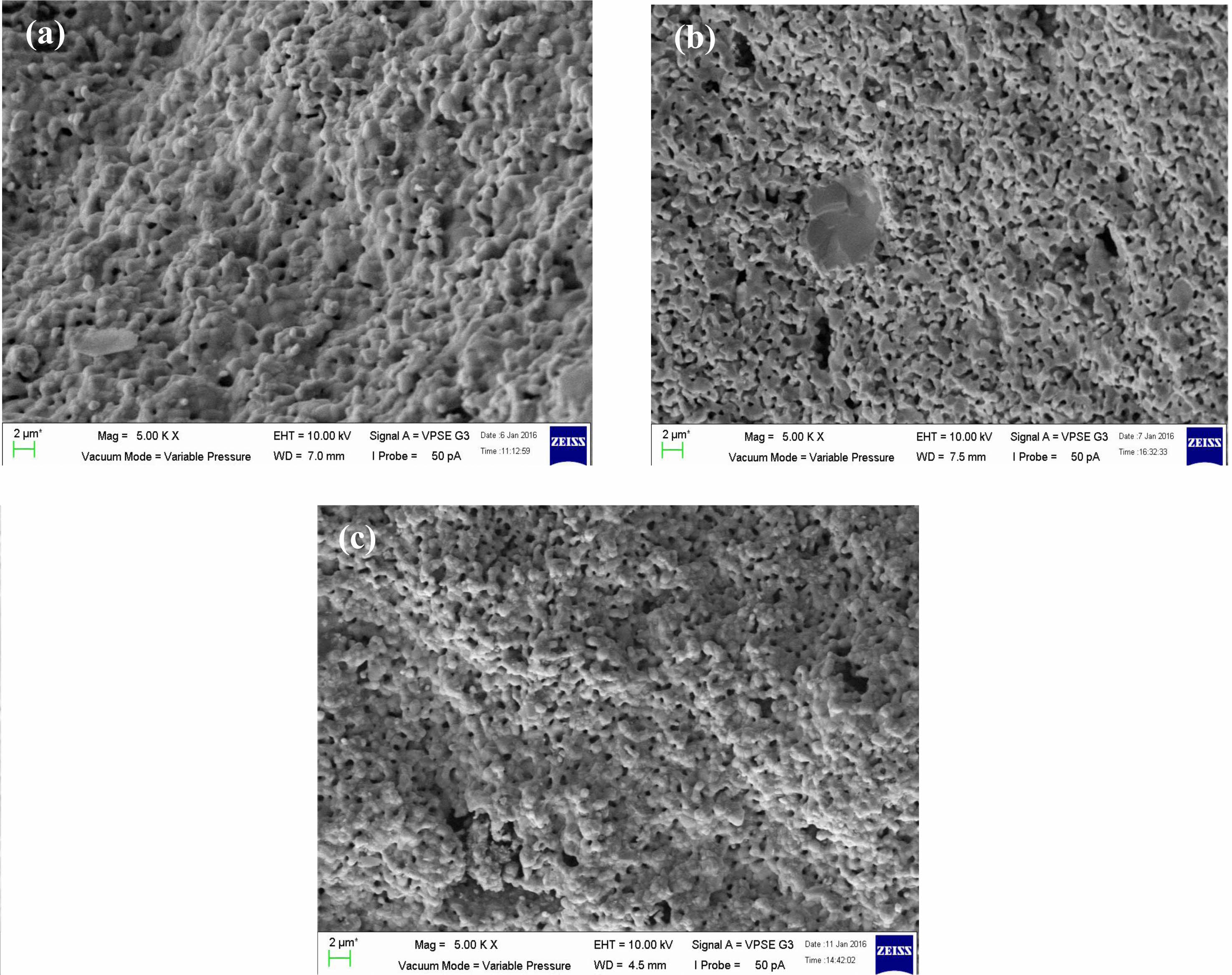
Fig. 3(a-c) shows SEM images exhibit microstructure of the sample were porous and the grains are merged with unequal sizes distributed inhomogeneously throughout the samples with irregular boundaries. Although the sizes of the samples were different from each other, the difference was small. For sample x = 0.4, it seems more porous than x = 0.3 and 0.5. This is proven by sample density in Table 2 where sample x = 0.4 is the lowest among the three samples which shows the samples are less dense. The sizes of the particles are aligned with the appearance in Fig. 3(a-c). Even though the density of the sample in Fig. 3(b) has less density, the average particle size is bigger than in Fig. 3(c) due to some of the particles merging and melting to form bigger particles. There is more void space between the grains and this fact supported the sample x = 0.4 is more porous than other samples.
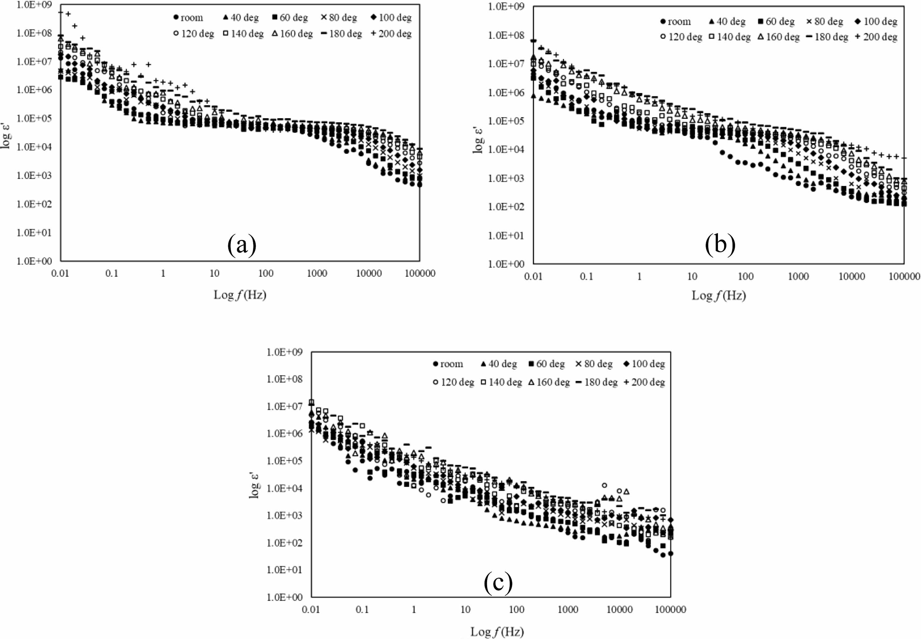
For electric properties, the data gained from the LCR meter which is capacitance (c) and conductance (G) were transformed into permittivity, ε*, and is shown in equation 2. Permittivity analysis is an analysis to know the ability of a material to polarize in the electric field. The real part, ε’ is known as the dielectric constant and is shown in Fig. 4(a-c) while the imaginary part, ε” is for dielectric loss of the sample shown in Fig. 5(a-c). For Fig. 4(a-c), the dielectric constant decreases as frequency increases in all temperatures due to dielectric dispersion [26]. This phenomenon can be explained based on space charge polarization largely eased by the movement of free space charge carriers in the form of Mn+3 and Mn+4 [26, 27]. The highly steep of dielectric constant in Fig. 4(a-b) at the frequency range 0.01 Hz-1 Hz is due to interfacial polarization that could happen because of inhomogeneities where the hoping electron are trapped [28]. At a certain frequency range of 1 Hz until 1 kHz, the value of ε’ is in plateau form due to the polarization phenomenon where the samples maintain the charges separation. As the temperature increased, the plateau condition also shifted to a higher frequency area which shows that the charge separation maintain at higher frequency. As in Fig. 4(c), ε’ decreases linearly as the frequency increase. The condition was due to polarization mechanisms no longer being able to follow the rapidly changing field which shows that the samples are having dielectric relaxation. As the temperature increase from 40 oC to 200 oC, the value of ε’ increases. The increment of ε’ with temperature could be due to enhanced drift velocity caused due to the thermal activation of hopping of the electrons [29]. It is clearly showing that the space charge polarization occurs at lower frequency and as the temperature increase, it influences the dielectric constant of all the samples. The dielectric constant decreases at frequency range after 1 kHz until 100 kHz is due to electronic polarization [30]. Dielectric loss derives from leakage conductivity, dielectric relaxation or intrinsic loss [31].

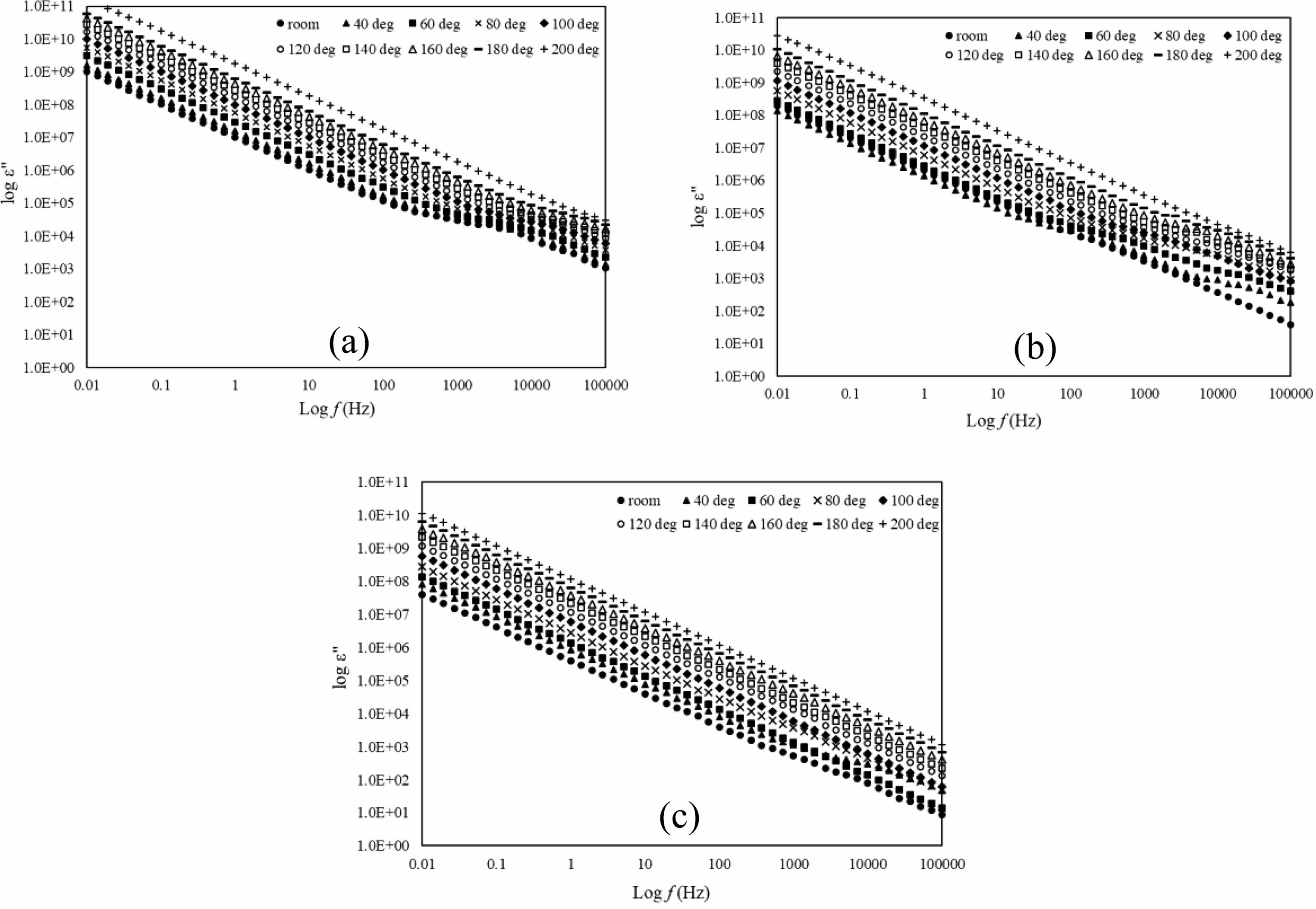
As for Fig. 5(a-c), the dielectric loss, ε” is linear with frequency with the slope is nearly -1 and this characteristic shows the samples are near d.c. conductivity [18]. At lower frequencies, dielectric loss for all samples shows higher value and increase as the temperature increases. At higher frequency between 1 kHz and 10 kHz the samples shown humps that is slowly disappear as the temperature increases. This is due to the interfacial polarization and the total charge carrier exaggerated as the temperature rise [32]. The humps also slowly dissapear as the Mg doping increases. This could be that Mg reduce the range between atoms consequently promotes change in mobility. The increase of dielectric loss as the frequency decrease may be due to the leak of conductance [33, 34].
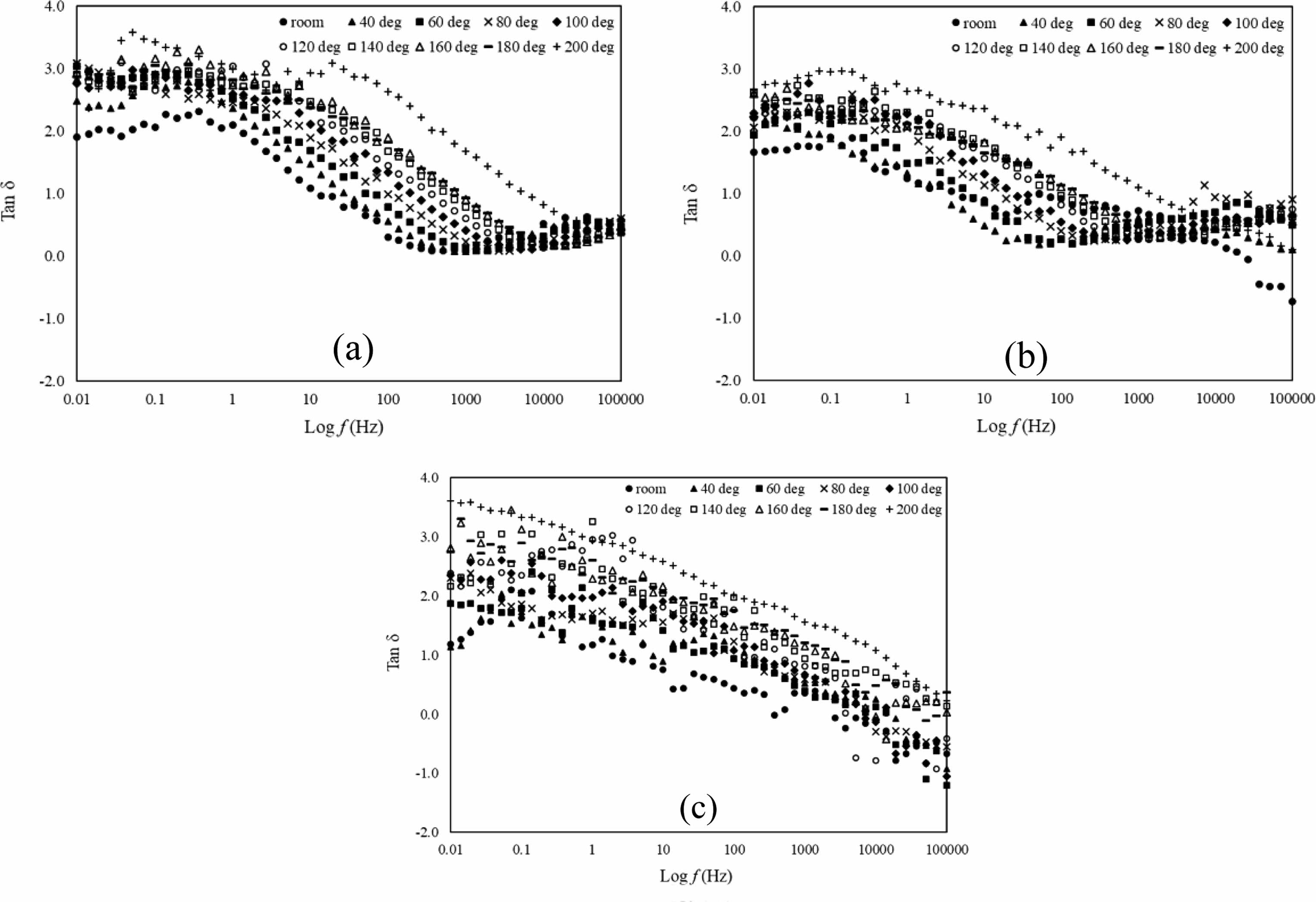
Another way to get dielectric loss information is by plotting graph of tan δ against log f which are shown in Fig. 6(a-c). Tan δ shows the value of dissipation of electrical energy due to electrical conduction, dielectric relaxation, loss from non-linear processes and dielectric resonance. In this paper, the tan δ value having plateau stage from 0.01 Hz until 1 Hz in all samples. Then it started to decrease rapidly from frequency range 1 Hz until 100 Hz and it is shifted to higher frequency as the temperature increases. High value of tan δ shows that the samples having more dielectric loss primarily due to the polarisation of the dielectric lagging behind the applied field, which causes an interaction between the field and polarisation, which in turn causes heating. For application reason, lower tan δ values are desired.
|
Fig. 2 X-ray diffraction patterns of La1-xMgxMn0.4Ti0.6O3 samples (Mg composition, x = 0.3, 0.4 and 0.5). The asterisk ‘*’ indicates the secondary phase. |
|
Fig. 3 The SEM images of La1-xMgxMn0.4Ti0.6O3 where composition x = (a) 0.30, (b) 0.40, and (c) 0.50. |
|
Fig. 4 log ε’ versus log f of La1-xMgxMn0.4Ti0.6O3 where composition x = (a) 0.30, (b) 0.40, and (c) 0.50 with temperature range from room until 200oC. |
|
Fig. 5 log ε” versus log f of La1-xMgxMn0.4Ti0.6O3 where composition x = (a) 0.30, (b) 0.40, and (c) 0.50 with temperature range from room until 200oC. |
|
Fig. 6 Tan δ versus log f of La1-xMgxMn0.4Ti0.6O3 where composition x = (a) 0.30, (b) 0.40, and (c) 0.50 with temperature range from room until 200oC. |
The samples La1-xMgxMn0.4Ti0.6O3 (x = 0.30, 0.40 and 0.50) were fabricate by using solid-state method. X-ray diffraction data confirmed its crystalline system is in a cubic structure with a space group of Pm3m. The SEM images exhibit microstructure of the samples was porous, and the grains are merged with unequal sizes distributed inhomogeneously throughout the samples with irregular boundaries. The dielectric constant of all samples at low-frequency range 0.01 Hz until 1 Hz are affected by interfacial polarization while at high-frequency range 1 kHz until 100 kHz was due to electronic polarization. The dielectric constant of all the samples is thermally activated. As for dielectric loss, it increases as the frequency decrease due to leakage of conductivity. From the tan δ graph, the value seems decreases as the frequency increase and it shows that at a lower temperature the sample is preferable for electronic device such as capacitor at lower frequency.
The author would like to thank Universiti Putra Malaysia for providing research facilities and providing grant (grant vote no: 9674100) for the financial support.
- 1. Z. Xiu, W. Yang, G. Chen, L. Jiang, K. Ma, and G. Wu, Mater. Des. 33 (2012) 350-355.
-

- 2. S. Das, S. Datta, A.K. Mukhopadhyay, K.S. Pal, and D. Basu, Mater. Chem. Phys. 122 (2010) 574-581.
-
- 3. Y. Hagedorn, in “Laser additive manufacturing of ceramic components: Materials, processes, and mechanisms” (Woodhead Publishing, 2017) p. 163-180.
-
- 4. D. Feng, X. Luo, G. Zhang, and Z. Xie, Mater. Chem. Phys. 185 (2017) 1-5.
-
- 5. S.P. Ratnayake, in “In Interfaces in Particle and Fibre Reinforced Composites” (Woodhead Publishing, 2020) p. 369-389.
-
- 6. M. Zhang, L. Li, W. Xia, and Q. Liao, J. Alloys Compd. 537 (2012) 76-79.
-
- 7. T. Santhosh Kumar, P. Gogoi, A. Perumal, P. Sharma, and D. Pamu, J. Am. Ceram. Soc. 97 (2014) 1054-1059.
-
- 8. V. Shanker, S. Kumar, and T. Surendar, Bull. Mater. Sci. 35 (2012) 1165-1171.
-
- 9. V.S. Samyuktha, R.P. Suvarna, and T.S. Rao, Int. J. Eng. Res. Technol. 5[5] (2016) 245-249.
-
- 10. C.L. Huang, C.H. Shen, and C.L. Pan, Mater. Sci. Eng. B. 145 (2007) 91-96.
-
- 11. D. Zheng and R. Zuo, J. Eur. Ceram. Soc. 37 (2017) 413-418.
-
- 12. N. Zhao, H. Fan, L. Ning, J. Ma, and Y. Zhou, J. Am. Ceram. Soc. 101 (2018) 5578-5585.
-
- 13. J. Yang, H. Zhang, X. Sang, A. Chang, and Z. Su, J. Mater. Sci.: Mater. Electron. 31 (2020) 7067-7075.
-
- 14. H. Asano, J. Hayakawa, and M. Matsui, Phys. Rev. B. 56 (1997) 5395.
-
- 15. E. Dagotto, T. Hotta, and A. Moreo, Phys. Rep. 344 (2001) 1-153.
-
- 16. K.H. Ahn, X.W. Wu, K. Liu, and C.L. Chien, Phys. Rev. B. 54 (1996) 15299.
-
- 17. H. Taguchi, M. Sonoda, M. Nagao, and H. Kido, J. Solid State Chem. 126 (1996) 235-241.
-
- 18. S.H. Mohd Hanif, W.C. Primus, A.H. Shaari, and J. Hassan, Adv. Mater. Res. 1107 (2015) 278-282.
-
- 19. S.H.B.M. Hanif, W.C. Primus, and A.E. Sinin, AIP Conf. Proc. 2332 (2021) 40003.
-
- 20. A.E. Sinin, W.C. Primus, A.H. Shaari, Z.A. Talib, and S. Hamdan, Adv. Mater. Res. 1107 (2015) 45-52.
-
- 21. L.M. Feng, L.Q. Jiang, M. Zhu, H.B. Liu, X. Zhou, and C.H. Li, J. Phys. Chem. Solids. 69 (2008) 967-974.
-
- 22. P. Jha, S. Rai, K.V. Ramanujachary, S.E. Lofland, and A.K. Ganguli, J. Solid State Chem. 177 (2004) 2881-2888.
-
- 23. S. Singh, P.A. Jha, S. Varma, and P. Singh, J. Alloys Compd. 704 (2017) 707-716.
-
- 24. Z. Zalita and S.A. Halim, Adv. Mater. Res. 501 (2012) 86-90.
-
- 25. Metallic, Covalent and Ionic Radii(r). https://www.wiredchemist.com/chemistry/data/metallic-radii. (accessed 31 Dec 2021).
- 26. B. Dhanalakshmi, K. Pratap, B.P. Rao, and P.S. Rao, J. Magn. Magn. Mater. 404 (2016) 119-125.
-
- 27. S. Ke, H. Fan, W. Wang, G. Jiao, H. Huang, and H.L.W. Chan, Composites, Part A. 39 (2008) 597-601.
-
- 28. M.H. Abdullah and A.N. Yusoff, J. Mater. Sci. 32 (1997) 5817-5823.
-
- 29. V.V. Soman, V.M. Nanoti, D.K. Kulkarni, and V.V. Soman, Phys. Procedia. 54 (2014) 30-37.
-
- 30. N. Adhlakha, K.L. Yadav, and R. Singh, Smart Mater. Struct. 23 (2014) 105024.
-
- 31. H. Moradmard, S.F. Shayesteh, P. Tohidi, Z. Abbas, and M. Khaleghi, J. Alloys Compd. 650 (2015) 116-122.
-
- 32. M.H. Abdullah and A.N. Yusoff, Pertanika J. Sci. Technol. 6 (1998) 95-105.
- 33. P.S. Neelakanta, J. Phys.: Condens. Matter. 2 (1990) 4935.
-
- 34. Y.B. Feng, T. Qiu, and C.Y. Shen, J. Magn. Magn. Mater. 318 (2007) 8-13.
-
 This Article
-
2023; 24(3): 446-452
Published on Jun 30, 2023
- 10.36410/jcpr.2023.24.3.446
- Received on Sep 27, 2022
- Revised on Feb 10, 2023
- Accepted on Feb 23, 2023
Services
- Abstract
introduction
materials and methods
results and discussion
conclusion
- Acknowledgements
- References
- Full Text PDF
Shared
Correspondence to
- Walter Charles Primus
-
Department of Science and Technology, Faculty of Humanities, Management and Science, Universiti Putra Malaysia Bintulu Campus, 97008 Bintulu, Sarawak, Malaysia
Tel : +6086-855741 Fax: +6086-855428 - E-mail: walter@upm.edu.my
Clean-Energy Research Institute(CRI), Hanyang University, 222, Wangsimni-ro, Seongdong-gu, Seoul, 04763, Korea
E-mail: jcpr@hanyang.ac.kr