


- Effect of hybrid ceramic addition on Al7075 for prompt utilization
P. Sathiamurthia,*, K.S. Karthi Vinithb, A. Sivakumara and N. Bagath Singhc
aDepartment of Mechanical Engineering, Kongu Engineering College, Perundurai, Erode, India
bDepartment of Automobile Engineering, Kongu Engineering College, Perundurai, Erode, India
cDepartment of Mechanical Engineering, Kurinji College of Engineering and Technology, Manapparai, Trichy, IndiaThis article is an open access article distributed under the terms of the Creative Commons Attribution Non-Commercial License (http://creativecommons.org/licenses/by-nc/4.0) which permits unrestricted non-commercial use, distribution, and reproduction in any medium, provided the original work is properly cited.
In recent engineering applications, lightweight aluminium composites are becoming more popular as an alternative for ferrous metals. The high cost of component manufacture has kept particulate metal matrix composites from being widely used in engineering applications. The goal of this research is to characterize stir cast Al-7075/B4C/Si3N4 reinforced hybrid composites. Hard ceramic reinforcements increase the microstructure, mechanical, and wear qualities of the material. B4C and ZrB2 particles were incorporated into the Al matrix at different weight percents, such as 2, 4, 6, and 8. The microstructure, and properties of mechanical as well as wear of ZrB2 and B4C particle composition were examined. In addition, SEM and XRD were used to investigate the castings' morphology. As a result, hardness and strength rise as the amount of B4C-ZrB2 in the composite increases. The Al7075 + 8% B4C + 1% ZrB2 composite outperform all the considered composition. Furthermore, with increasing sliding distances, the specific wear rate increases and the coefficient of friction decreases. Because of its outstanding mechanical and wear properties, the hybrid Al7075-B4C-ZrB2 material is the excellent choice of upper wing requirements
Keywords: Al7075-B4C-ZrB2 hybrid composites, Wear properties, Microstructure, Compression test, Friction
Many different forms of aluminium composites were used in a variety of applications, including automotive, aviation, maritime, infrastructure, and healthcare, due to their improved mechanical properties, greater corrosion and wear resistance [1-3]. Aluminium composites with secondary particles have better mechanical qualities than other materials [4]. Aluminium composites reinforced with ceramics have key properties such as toughness, endurance; wear resistance, and dimensional consistency. Moreover, several factors influence the increase of properties [1]. Over last two decades, researchers have focused on incorporating various ceramic particles with aluminium material to increase its properties [5, 6]. In addition, materials from the Al 7075 series have been utilized to make camping knives, aircraft, missile tail cones, and internal combustion engine casings [7, 8]. These materials are strong, lightweight, and long-lasting. In a range of industries, researchers who switched from single unified to matrix composites had addressed worldwide requirements on great efficiency, relatively inexpensive and excellent quality materials [9, 10]. Al-7075 alloy has been utilized as a composite materials and augmented by appropriate individual and numerous strengthening elements including such SiC, B4C, ZrB2, TiB2, fly ash, and other materials to produce composites with enhanced durability than that of the basic metals [11]. Among the aluminium alloy groups, Al7075 has excellent material characteristics. This has the most often utilised alloying material due to their superior strength structural applications, so this is commonly found in aircraft and automobile parts [12]. Aluminium metal matrix composites were fabricated by utilizing powder metallurgy processes. Stir casting had remained the most investigated process of manufacturing selected materials, because of their inexpensive easy
process. However, several experts have found that stir casting improves the wettability of molten metal with ceramic particles [13, 14]. Wear has been a significant factor in a wide range of engineering applications. Despite the fact that, wear as well as friction performance of a variety of alloying materials is un lubricated circumstances has been thoroughly investigated using single reinforcement [15, 16]. Furthermore, wear behaviour of Al 7075 reinforced with ZrB2 as well as B4C elements was investigated using sliding wear experiments with a pin-on-disc device. The findings of the experiment demonstrate that composites have reduced wear rates [17-20]. Al 7075 reinforced with TiB2-B4C has achieved a yield strength of 522 MPa and improved wear resistance [21]. The Zn-Al2O4 ceramics achieve the maximum dielectric permittivity of 220 at 10 kHz and the lowest leakage current of 3.9810-6 A/cm2 at 0.25 kV/cm, which is better than that of the single sintering ceramics [22]. Likewise, to the manner in which steam pressure was influenced, aluminium metal matrix composite [23]. According to SEM images and BET results, uniform Co: MgAl2O4 nano powder analysis results reveal that the particles' specific surface area reached 36 m2/g and their primary particle size was 39 nm [24]. The impact of the MgO-CaO-Al2O3-SiO2 ceramic study reveals that the maximum relative density of the MCAS-doped samples sintered at 1500 and 1600 °C was 99.7%, with a density of more than 98%. Because further doping caused excessive grain growth, the sample prepared with 3 wt% MCAS and sintered at 1500 °C for 1 h had the highest hardness (18 GPa) [25]. Furthermore, Higher brake thermal efficiency (BTE) and lower specific fuel consumption were achieved by an alumina (Al2O3) thermal barrier coated with partially stabilized zirconia (PSZ) and yttria stabilized zirconia (YSZ) [26]. However, research on these hybrid composites manufactured from reinforced ceramics has been limited. Using the stir casting technique, an attempt is made to manufacture Al7075-ZrB2-B4C hybrid composites and characterise their properties.
Materials and Fabrication
Al 7075 was used in this investigation because it contains magnesium and silicon as main hybrid composite elements. Other aluminium composites were heavier than hybrid aluminum-magnesium composites. In aircraft production, reinforced Hybrid Composites composed mostly of aluminium have played a key role. The chemical composition of Al 7075 has been seen in Table 1. Likewise, physical properties of Al 7075 have been described in Table 2. The melting point of Al7075 is 660 °C.
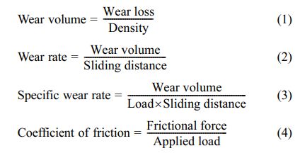
Ceramics are inorganic, nonmetallic materials that are often crystalline oxide, nitride, or carbide. Likewise, Ceramics include components like carbon and silicon. Furthermore, ceramics have a brittle hardness, are strong in compression, but weak in shearing and tension. Ceramics can tolerate temperatures ranging from 1000 °C to 1600 °C. Zirconium Di-boride (ZrB2) and Boron carbide (B4C) supplemental reinforcing was provided by granules size of 10-15 µm. ZrB2 has a
hexagonal crystal shape and can be an extremely covalent refractory ceramic material with a melting point of 3246 °C, ZrB2. Typically, ZrB2 pieces are hot pressed and then machined to shape. The covalent nature of ZrB2 and the presence of surface oxides, which increase grain coarsening before densification during sintering, make it difficult to sinter. Likewise, B4C would be a covalent ceramic used in tank armour, bulletproof vests, engine sabotage powders, and a variety of other industrial uses. Behind cubic boron nitride and diamond, it is one of the hardest known materials. Because of its capacity to absorb neutrons without generating long-lived radionuclides, boron carbide seems to be a promising absorber for neutron radiation from nuclear power plants and anti- personnel neutron bombs. The Fig. 1a-b describes ZrB2 and B4C respectively.
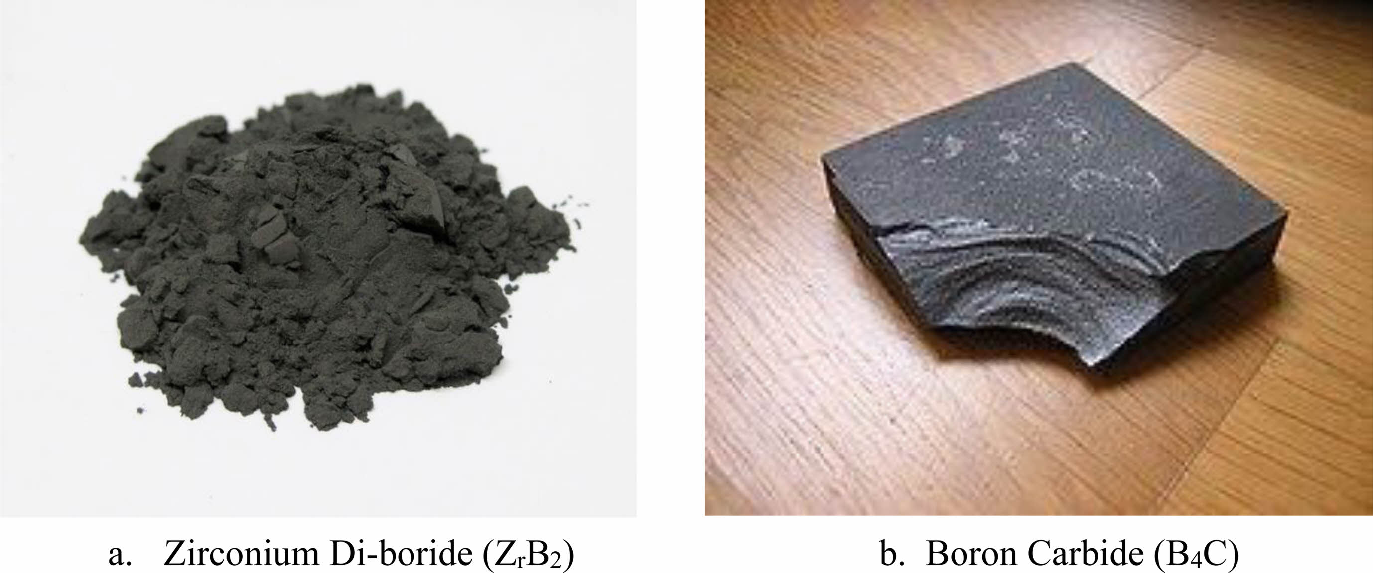
The stir casting method has been utilized to fabricate the specimen. To create different cast morphologies, a mechanical stir caster was designed and built. The quasi material has been crushed inside this hot fibrous space among grooved rotor and crucible. The viscoelastic measurements were made possible by connecting the churning rotor to the propeller with an autonomous in-line torque metre. Four resistance heating elements were used to heat the caster furnace. Fig. 2a depicts the stir casting apparatus in detail. The temperature readings were shown on control panel, and the furnace was heated to a high degree to flake the metal. The base metal has been placed in the crucible, followed by the reinforcements for the casting process. The temperature readings were shown on control panel of this equipment. The maximum temperature allowed was 700 °C, with temperature gradient control within the limited area of crucible where shearing takes place. Linear drive was make available to rotor, allowing stir caster to be evacuated after chosen shear period. The gadget also served as a tachometer during shear when the rotor was in the lower position. In addition, moulding often known as moulding, has been the technique of shaping liquid or malleable raw material using a rigid frame known as a mould or matrix. This could have been
created from a pattern or model of the final product. For the moulding procedure, a rectangular steel mould is employed. The rectangular steel mould is 8 mm thick and measures 100×100 mm in size. The crucible mixture was poured into the rectangular steel mould after it had been stirred. Fig. 2b describes moulding process. The next step is solidification. The liquid mixture injected into the mould solidifies during the solidification process. Atoms from the liquid mixture begin to link together and form crystals during solidification. Multiple crystals begin to develop in the liquid mixture as it begins to harden. Solidification is the process of turning a liquid into a solid below the melting point. The hardened composite material is taken from the mould when it has solidified.
Microstructure Measurement
Microstructure is the structure of a prepared surface or thin foil of materials as seen under a microscope at magnifications greater than 25x. The microstructure of a material can be examined for physical attributes such as endurance, hardness, rigidity, corrode, and wear resistance, which control the application of these materials in industrial practise. The Fig. 3 describes optical microscope apparatus.
Surface preparation and Diamond polishing
The specimen was processed on finer emery sheets from 120 to 1000 grit to get a rather smooth surface. This was lubricated with water to keep it cool and eliminate the grinding products. Some material may need to be removed on the lathe or grinding machine first if the sample wasn't flat. The sample should be dragged forward and backward on the paper until the entire surface was covered in unidirectional scratches. Following that, the paper gets cleaned under running water to remove any dirt associated with the paper grade. It's then ground on a finer paper such that the
scratches are at right angles to the ones created by the previous one. This makes it simple to tell when the scratches from the coarser paper have been removed completely. This process was done for each of the papers accessible. Undercutting was prevalent during the fabrication of finely lapped surfaces unless certain safeguards are taken. It's the process of removing softer constituents more quickly than tougher constituents, causing the harder material (typically the aggregate) to rise above the softer components. The slice rides on the high, hard regions of the lapping process, while grinding compound gathers under the soft portions. The rounded border of hard aggregate standing above an undercut paste increases the visible aggregate area. At the point when the theoretical flat-lapped surface transforms to a slope down into the paste, there is no sharp line or change in surface texture. In such a slice, no amount of reasoning or mental reconstruction of the surface can allow an accurate calculation of the paste aggregate boundary or paste-aggregate ratio. The paste-aggregate boundary is smoothed over where the surface falls below the theoretical true surface and cannot be identified by a view from above, such as through a microscope. The length of each doubtful region was indicated by arrows.
Diamond paste comes in a variety of sizes. Polishing can begin with 1 μm, 0.5 μm, or 25 μm if necessary. When the surface is satisfactory, the polishing is continued with smaller diamond paste. For the various sizes, separate wheels must be utilised. Check the appropriateness of diamond paste for a certain material's polishing process. A variety of grinding pastes are available. In most circumstances, two polishing, namely 6 μm and 1 μm, should enough. The first wheel has 6 μm diamond paste, while the second contains 1 m diamond paste. Both polishing wheels were lubricated with an organic liquid, and water must not come into touch with them. First, the 1 μm diamond wheel was employed. The specimen was forced down onto the polishing wheels, which have been lubricated. It's vital not to keep the specimen in one orientation for too long, as this will
cause some micro structural components to “dragging”. Small spherical particles, for example, can generate a comet-like "tail." To avoid this, the specimen was continuously oscillated around the vertical axis.
Wear Test
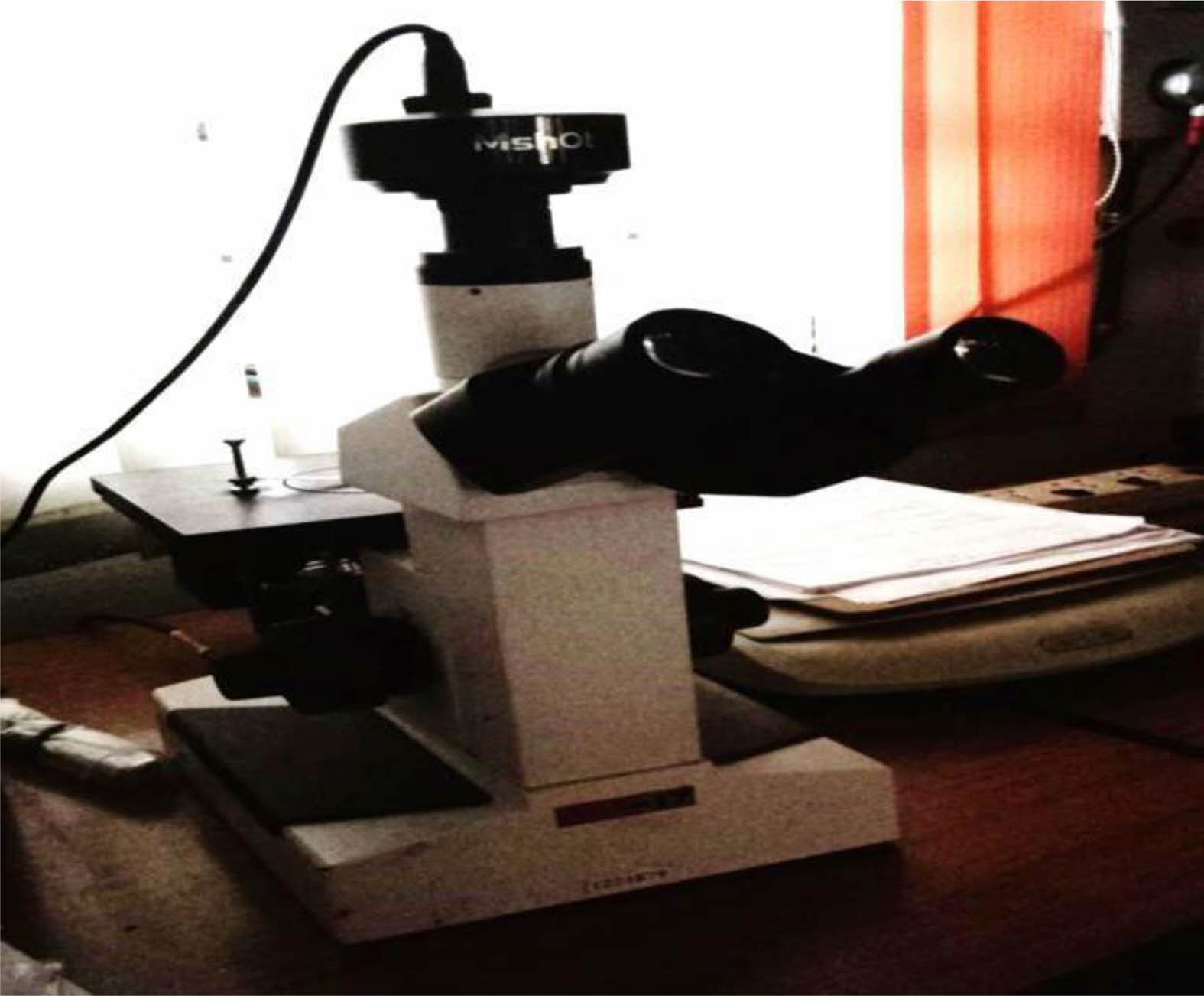
A pin on disc tester has been utilized to conduct dry sliding wear tests. Powder metallurgy billets were machined into pin specimens has diameter and length of 8 mm, 25 mm respectively. Grinding has been performed using silicon carbide paper. Likewise, washing has been done using to prepare the contact surfaces. The stationary pins were loaded vertically on to a spinning EN 31 steel disc with a hardness of HRC 64 using a pin holder. All of the trials were done in a controlled environment. Load has been delivered to specimen via cantilever mechanism while sliding, and get into make contact with rotating disc at a track radius of 70 mm. Three separate investigative situations of load, sliding distance, and sliding velocity were used to measure wear and friction. The applied dead weights were 5, 10, and 15 N. Likewise, sliding distances were 400, 800, 1200, 1600, and 2000 m. This has been achieved by keeping sliding speed as constant at 1.41 m/s. The pins were thoroughly cleaned after each experiment and measured with a sensitive electronic scale with a weight loss of 0.1 mg. For composites with 5, 10, and 15% Fly ash percentages, weight loss data was converted to volume loss data using the density of pure Copper 8940 kg/m3 and density of 9455.50 kg/m3, 9971 kg/m3, and 10486.50 kg/m3 correspondingly. From observed frictional force and applied load, the coefficient of friction (COF) was calculated. This technique has been carried out of each test situations. The ASTM G99 is used for the wear test studies. The following equations (1)-(4) was used to calculate wear volume,
wear rate, specific wear rate, and coefficient of friction.
|
Fig. 1 Ceramic materials |
|
Fig. 2 Fabrication Apparatuses |
|
Fig. 3 Optical Microscope Apparatus. |
Stir Casting Fabrication
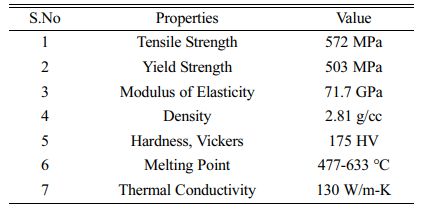
Stir casting has been used to make the Al7075-ZrB2-B4C metal matrix composite. The Al7075 micro powder is melted in a crucible by heating it at 750 °C in a resistive furnace until the matrix material was entirely melted. After melting the matrix material in an inert atmosphere for about 20 minutes, automatic stirring was performed with the help of a Motor at a stirring rate of 600 RPM. By using appropriate feeding attachments, the ZrB2-B4C particles are evenly fed into the molten metal alloy at this stage. In the meantime, a stirrer spinning at 400 rpm creates a vortex out of the scattered treated molten Al7075 alloy. At a pouring temperature of 700 °C, the dispersion treated Al7075 is poured straight into the mould. After that, the mould is held still to solidify. The weight percentage of ZrB2-B4C in the matrix alloy was changed between 2%, 4%, 6%, and 8% as shown in Fig. 4. Furthermore, the Fig. 5 shows optical microscope image of fabricated specimen weight percentage of 2%, 4%, 6%, and 8% respectively.
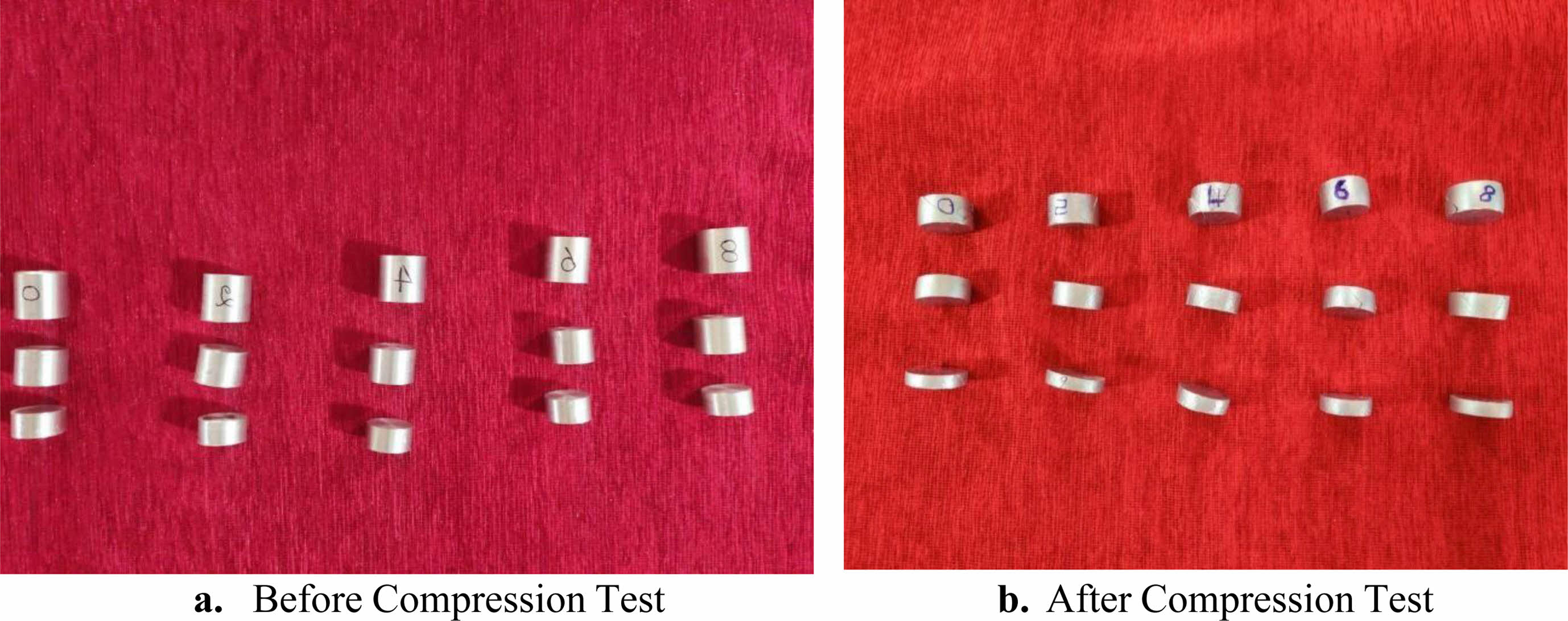
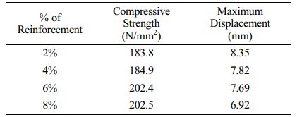
On a specimen with an 18 mm diameter and 18 mm, 13.5 mm, and 9 mm length, compression tests are performed in the same way as tension testing. The Universal Testing Machine has been used
for the testing. Each load interval's length change was measured and recorded until the load breaks. The behaviour of the test specimen for compression test is analyzed using ASTM D695 standard. The Fig. 6a-b shows before and after compression test specimens. Furthermore, Table 3 describes Compression test results. Based on the compression test results, it revealed that the maximum load it can be accommodated before the fracture.
Effect of Specific Wear rate on sliding distance
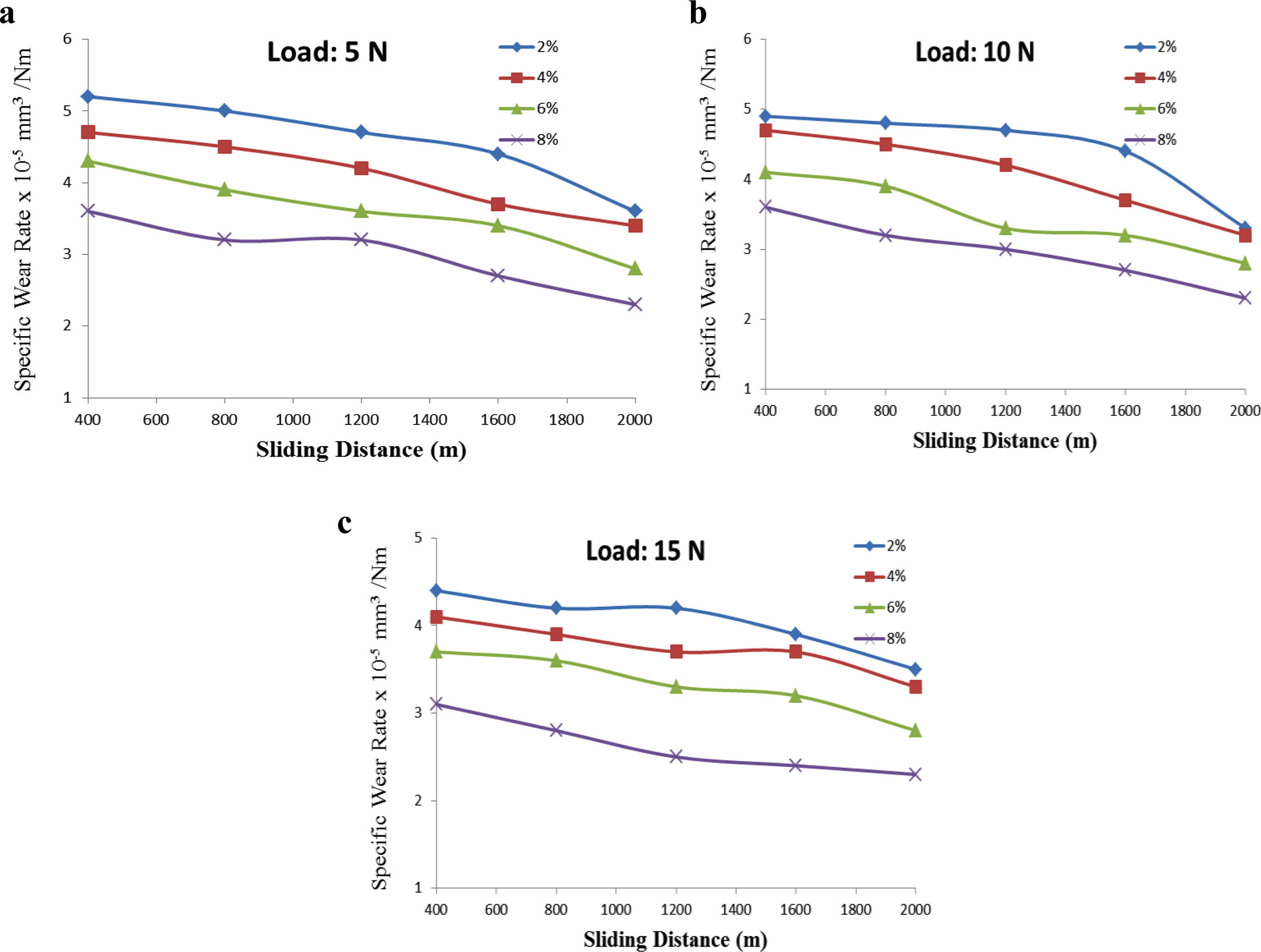
The effects of load (5, 10, and 15 N, respectively) on specific wear rate with respect to sliding distance were seen in Figs. 7a-c. The sliding distance has been shown by the x-axis, while the wear rate represented by the y-axis. The coating time was 30 minutes, rotating speed was 500 rpm, and temperature remained constant throughout the process. The track diameters were 20, 25, 30, and 35 mm, with sliding distances of 62.83, 78.53, 94.25, and 109.96 metres. Specific wear rates for sliding distances with a 5 N load were 0.10202, 0.16325, 0.22205, and 0.23317 × 10⁻⁵ (mm3/Nm). At a 10N load, the specific wear rates for sliding distances were 0.20372, 0.27208, 0.28197, and 0.31071 × 10⁻⁵ (mm3/Nm). Similarly, with regard to the sliding distance, the curve of 10 N load reflecting specific wear rate increases progressively. The wear rates for sliding distances were 0.61215, 0.71624, 0.91591, and 0.99934 × 10⁻⁵ (mm3/Nm) at 15 N load. With respect to the sliding distance, the curve of 5 N load reflecting specific wear rate grows steadily, lowers somewhat, and then increases again. With regard to the sliding distance, the 15 N load curve, which represents wear rate, steadily increases.
Effect of coefficient of friction on sliding distance
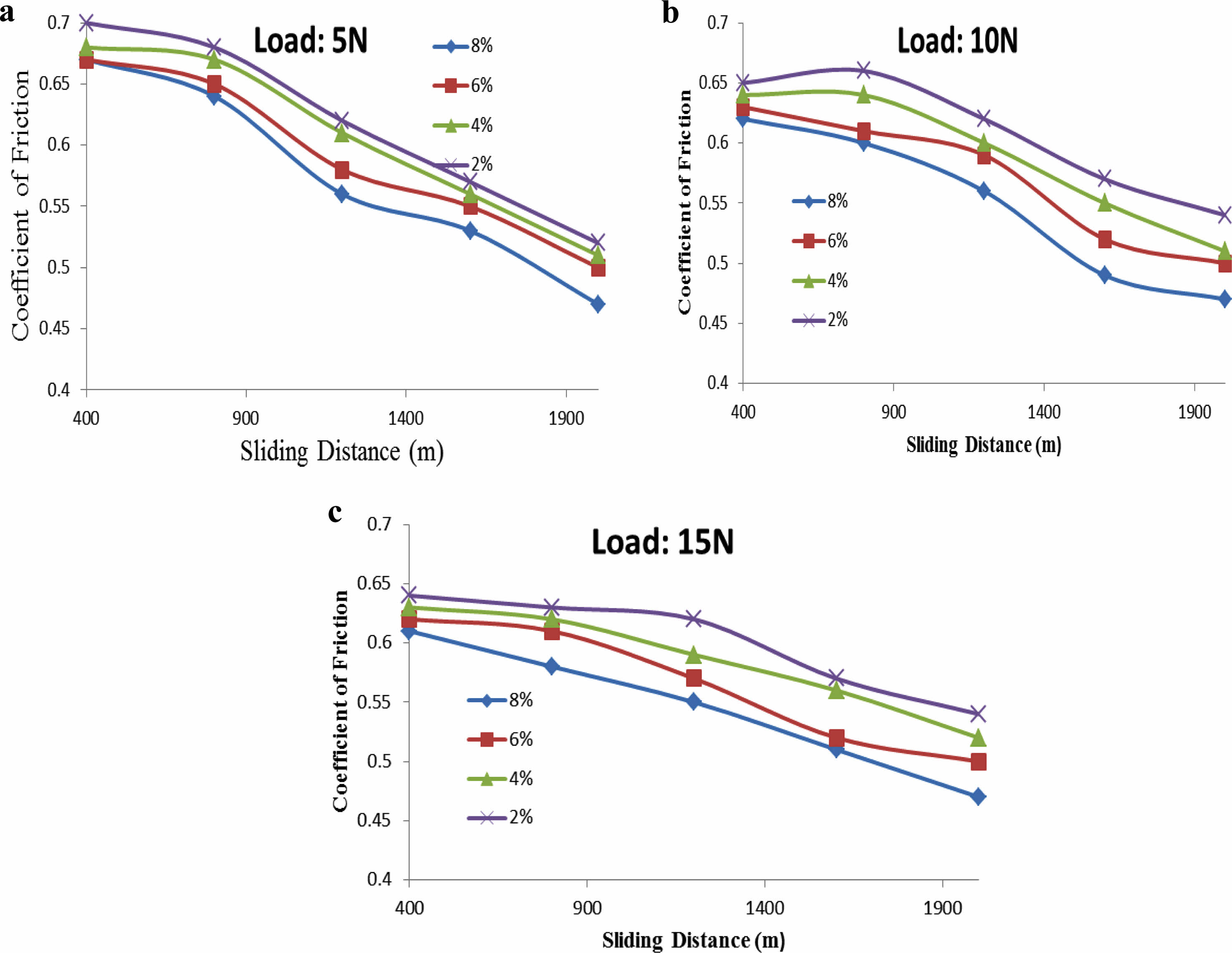
Fig. 8a-c depicts the COF as a function of sliding distance for a 5 N load, a 70 mm track radius, and a 1.4 m/s sliding velocity. COF diminishes as sliding distance increases, as shown in the figure. While sliding, friction warmed the contact areas. Frictional heating continues when the counter
surfaces were in relative motion because there was inadequate time for heat dissipation. Furthermore, due to reduced temperature, gradient of specimen surfaces with respect to the bulk specimen and its surroundings has been minimised. This also results in a slower rate of heat dissipation; but, after a certain amount of time, temperature rises dramatically, and temperature gradient rises, resulting in a faster rate of heat dissipation. Sliding action is increased due to the greater flow ability of the material on the specimen surface; this minimises frictional heating and, thus, reduces the COF.
Worn surface topography
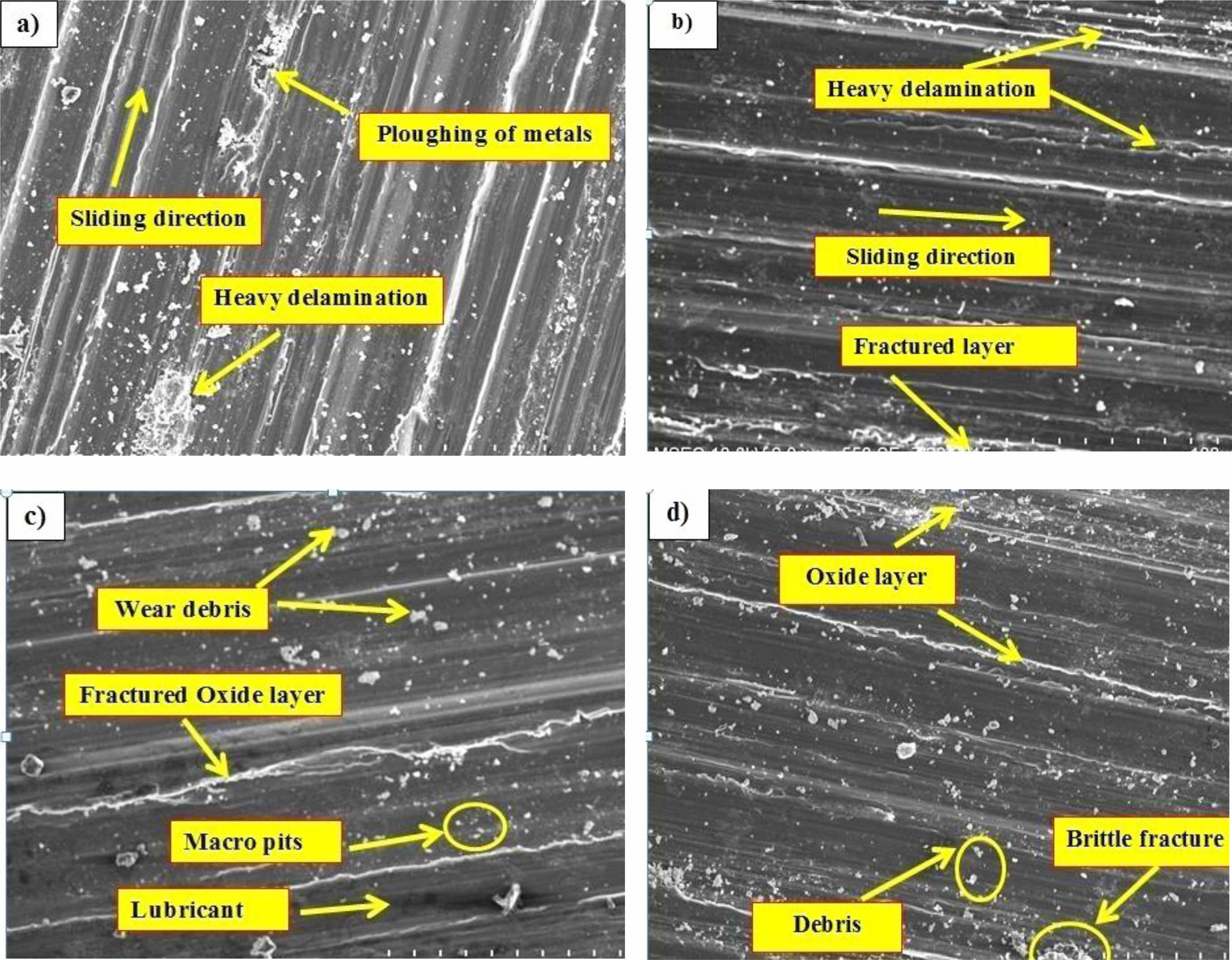
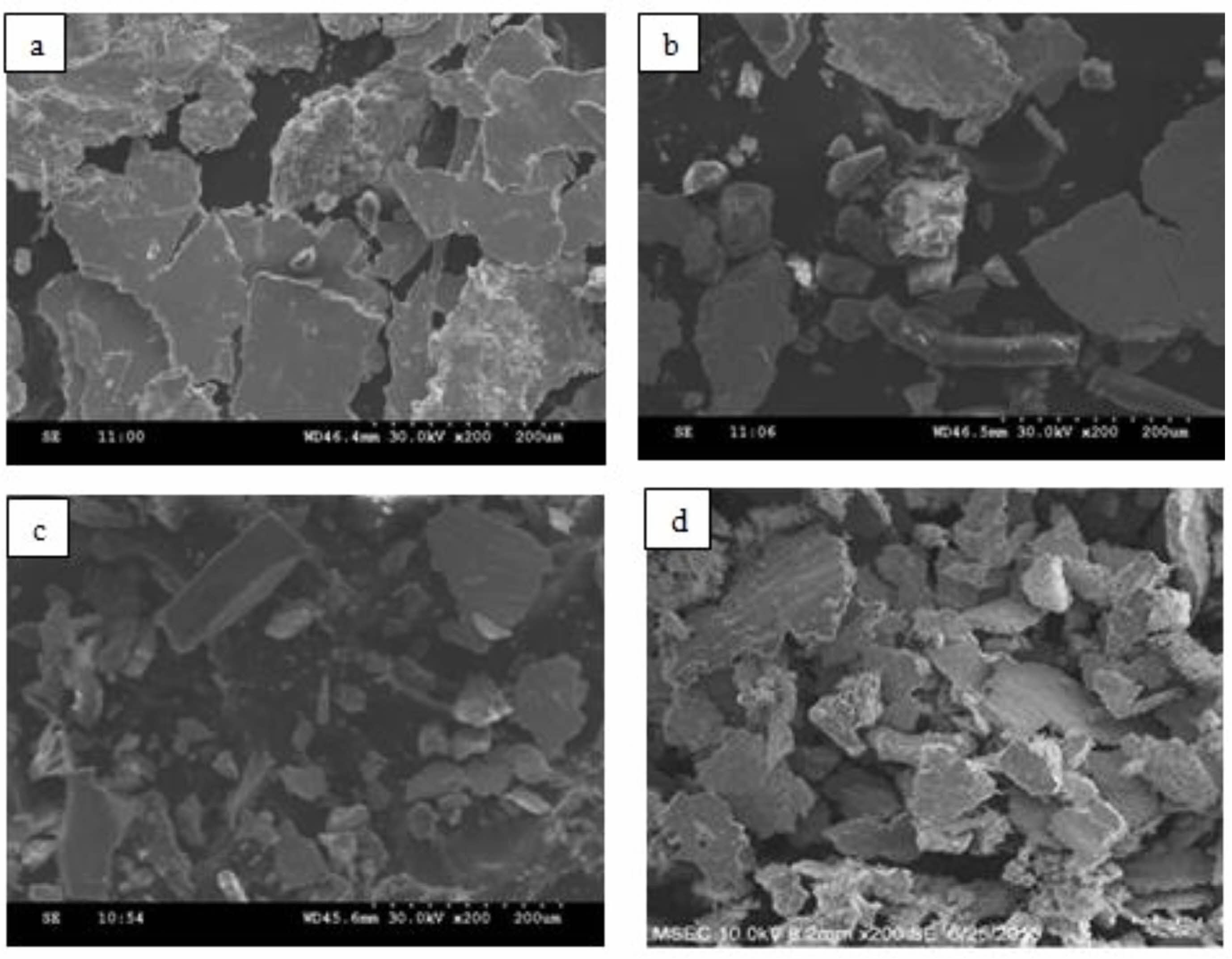
Scanning Electron Micrographs (SEM) was used to conduct a comprehensive micro structural analysis of worn surfaces of Al-7075 and its composites. Figs. 9a-d shows SEM results of Al7075-ZrB2-B4C composite worn surfaces. After testing, SEM surface photos at high load 15 N have been chosen and examined fully to highlight the difference in wear process. Over the sliding surface, a transfer layer of compacted wear debris may be seen, as well as wear tracks. Before being detached, this layer reaches a certain thickness, resulting in the formation of wear debris. The load and sliding speed define the area of cover provided by this transfer layer, which rises with increasing load due to higher frictional heating and thus better compaction. Another explanation for composites' reduced wear rate is their higher hardness compared to pure copper, which results in a smaller actual area of contact and thus a lower wear rate. Excessive delimitation of aluminium surface layers results in high wear loss, which increases as the sliding distance increases, as described in Fig. 9a. Adding 15% B4C-ZrB2 particles to the aluminium matrix significantly increased hardness of composite and reduced extent of plastic deformation of the matrix. Composite's wear loss is significantly minimised in this scenario. At higher loads, a closer examination of the surface exposes agglomerates of loose and small debris particles that formed.
Larger debris particles fracture under increasing stresses, resulting in finer debris particles. A closer look on SEM analysis in Fig. 9b-d exposes grooves running with wear direction. During wear, strong bearing steel ball counter body ploughs into tribo layer, forming grooves. Tribo layer on worn Al-7075 was thick in nature along transverse direction, and deep grooves on the surface are readily visible in comparison to other cases.
Wear debris Analysis
The wear debris particles were collected during testing at a maximum load of 15 N and discussed more below. SEM was used to investigate the microstructure of wear debris made of Al-7075 and its composites in detail. Wear debris of Al-7075-percent B4C-ZrB2 composite is shown in SEM images (Fig. 10a-d). When comparing pure Al-7075 to Al-7075-B4C-ZrB2 composites, SEM inspection of debris confirms the existence of Oxide, while close observation of the scar reveals a dense stack of layers, indicating increased wear volume. When compared to all Al7075-B4C-ZrB2 composite materials at 15 N loads, the creation of tribo layer and its area of coverage increased with the rise in load observed in Fig. 9(a-d). On the thick tribo layer, brittle break can be seen pretty clearly. Although the strengthening of W increases its hardness, it also causes wear debris to smear. The poor cohesive strength of the Al7075 matrix and the B4C-ZrB2 reinforcement could explain this.
|
Fig. 4 Fabricated specimens. |
|
Fig. 5 Optical microscope image of fabricated specimen. |
|
Fig. 6 Compression test specimens. |
|
Fig. 7 Sliding Distance Vs Specific Wear Rate. |
|
Fig. 8 Sliding Distance Vs coefficient of friction. |
|
Fig. 9 Worn purpose image of tested specimen. |
|
Fig. 10 Wear debris image of tested specimen |
1. Stir Casting Technique was used to make the Al7075-B4C-ZrB2 composites. Using JCPDS files, the XRD pattern of Al7075-B4C-ZrB2 was validated by the various peak intensities.
2. The hardness of the Al7075-B4C-ZrB2 composites varied mostly related on the reinforcing particle weight percentage. The hardness value grew as the fraction of B4C-ZrB2 increased. In comparison to pure Al7075, it shows an improvement of 8%.
3. The specific wear rate of Al7075-B4C-ZrB2 composites has been investigated using dry sliding wear on an EN31 steel counter face.
4. Specific wear rate for hybrid composites reduces as (B4C-ZrB2) reinforcement has been added, and grows linearly as applied stress and sliding distance increase.
5. Steady state COF for Al7075-B4C-ZrB2 composites reduces with load in the 5-15 N range.
Effect of B4C reinforcement on steady state COF was observed at lower loads, albeit insignificant.
6. Microstructures of Al7075-B4C-ZrB2 composites have revealed that increasing load reduces porosity and increases stresses, Poisson ratio, and strain, as well as reduced aspect ratio specimens with high load carrying ability.
The authors are grateful to respective author’s college management for their support in successful completion of this project work.
- 1. F. Nturanabo, L. Masu, and J. Baptist Kirabira, Al Alloys and Comp. 13 (2020) 1-24.
-

- 2. A. Chandrashekar, B.V. Chaluvaraju, A. Afzal, D.A. Vinnik, A.R. Kaladgi, S. Alamri, C. Ahamed Saleel, and V. Tirth, Symmetry 13[4] (2021) 1-38.
-
- 3. Nirala, S. Soren, N. Kumar, Y. Shrivastava, R. Kamal, A.I. Al-Mansour, and S. Alam, Materials. 15[6] (2022) 1-20.
-
- 4. K.K. Alaneme, A.V. Fajemisin, and N.B. Maledi, J. Mater. Res. Technol. 8[1] (2019) 670- 682.
-
- 5. D.M. Shinde, P. Sahoo, and J.P. Davim, Adv. Compos. 29(28) (2020) 1-28.
-
- 6. S. Pan, K. Jin, T. Wang, Z. Zhang, L. Zheng, and N. Umehara, Friction 10 (2022) 1596-1634.
-
- 7. E.E. Feldshtein, L.N. Dyachkova, and J. Patalas- Maliszewska, Materials, 14[1] (2021) 1-12.
-
- 8. A.S. Mohammed, O.S. Aljebreen, A.S. Hakeem, T. Laoui, F. Patel, and M.M. Ali Baig, Materials, 15[3] (2022) 2-13.
-
- 9. D.K. Rajak, D.D. Pagar, P.L. Menezes, and E. Linul, Polymers 11[10] (2019) 1-37.
-
- 10. Mirabedini, A. Ang, M. Nikzad, B. Fox, K.T. Lau, and N. Hameed, Adv. Sci. 7[11] (2020).
-
- 11. D.J. Joseph, L.S. Mageshwaran, and G.S. Neveen, Int. J. Eng. Res. Technol. 7[6] (2019) 1-7.
- 12. Kloeckner metals, Comparing 7075 Aluminum Vs 6061. (2021) 1-8.
- 13. S. Gudipudi, S. Nagamuthu, K.S. Subbian, and S.P.R. Chilakalapalli, Eng. Sci. Technol. an Int. J. 23[5] (2020) 1233-1243.
-
- 14. E.W.A. Fanani, E. Surojo, A.R. Prabowo, and H.I. Akbar, Metals 11[12] (2021) 1-30.
-
- 15. K. Friedrich, Adv. Indus. and Engg. Poly. Res. 1[1] (2018) 3-39.
-
- 16. M. Niemczewska-Wójcik, M. Pethuraj, M. Uthayakumar, and M.S.A. Majid, Materials. 16[1] (2023) 1-23.
-
- 17. R. Suresh, J. Mech. Behav. Mater. 29[1] (2020) 57-68.
-
- 18. R. Gupta, T. Nanda, and O.P. Pandey, T. Nonferr. Metal. Soc. 31[12] (2021) 3613-3625.
-
- 19. K.V.S.L. Dathathreya, T. Ravindra Andukuri, V. Lakshmi Prathyusha, and T.V.R. Ramakoteswara Rao, Int. J. Eng. Res. Technol. 11[1] (2022) 161-167.
-
- 20. K.M. Senthil Kumar, A. Sivakumar, Rohokale Milind Shivaji, S.K. Tamang, and M. Giriraj, J. Ceram. Process. Res. 23[2] (2022) 233-236.
-
- 21. R. Malkiya Rasalin Prince, D. Arulkirubakaran, Tapas Debnath, S.P. Arunkumar, N. Bagath Singh, R.B. Jeen Robert, and I. Living Prephet, Adv. Mater. Process. 8[4] (2022) 4209-4228.
-
- 22. Yuze Xue, Mingwei Zhang, Le Xin, Luchao Ren, Panpan Lv, Hang Zhan, Jing He, and Jiwei Zhai, J. Ceram. Process. Res. 24[2] (2023) 336-341.
-
- 23. R. Santhanakrishnan, V.S. Thangarasu, R. Arravind, and V. Ramachandiran, J. Ceram. Process. Res. 24[1] (2023) 174-181.
-
- 24. Wang Chuanyun, Yang Wei, Wang Zhiqi, Liu Bina, Li Shihua, Lu Taoa, Li Xueren, Miao Weipeng, and Luo Wei, J. Ceram. Process. Res. 24[2] (2023) 374-378.
-
- 25. D. Lee, H.S. Hong, H. Jeong, and S.-S. Ryu, J. Ceram. Process. Res. 23[2] (2022) 149-153.
-
- 26. P. Mohan Kumar, V.C. Uvaraja, and P. Madhu, J. Ceram. Process. Res. 23[5] (2022) 647-655.
-
 This Article
-
2023; 24(3): 429-438
Published on Jun 30, 2023
- 10.36410/jcpr.2023.24.3.429
- Received on Jun 29, 2022
- Revised on Feb 7, 2023
- Accepted on Feb 7, 2023
Services
- Abstract
introduction
experimental details
result and discussion
conclusions
- Acknowledgements
- References
- Full Text PDF
Shared
Correspondence to
- P. Sathiamurthi
-
Department of Mechanical Engineering, Kongu Engineering College, Perundurai, Erode, India
Tel : +91-9894157003 Fax: 04294-225777 - E-mail: sathiam10@gmail.com
Clean-Energy Research Institute(CRI), Hanyang University, 222, Wangsimni-ro, Seongdong-gu, Seoul, 04763, Korea
E-mail: jcpr@hanyang.ac.kr