


- Research progress on the interfacial phases of ceramic matrix composites
Weina Guo and Yantao Gao*
School of Textiles and Fashion, Shanghai University of Engineering Science, Shanghai 201620, China
This article is an open access article distributed under the terms of the Creative Commons Attribution Non-Commercial License (http://creativecommons.org/licenses/by-nc/4.0) which permits unrestricted non-commercial use, distribution, and reproduction in any medium, provided the original work is properly cited.
Continuous fiber toughened ceramic matrix composites (CMCs) have a wide range of applications in fields of aerospace vehicles and nuclear power plants because of their excellent properties. As one of the basic components of CMCs, the interfacial phase plays a great role in the performance of CMCs. By adjusting the interfacial phase, the toughening mechanisms such as fiber pull-out and debonding of CMCs can be brought into full play. The paper introduced the design principles of interfacial engineering of CMCs. The methods of interfacial preparation and interfacial strength testing of CMCs were summarized, and then the advantages and disadvantages of each methods were analyzes. The recent status of interface phase of CMCs was also reviewed. Finally, the development direction of interface phase of CMCs was prospected
Keywords: CMCs, Interface, Preparation, Optimization, Development
CMCs is a new type of material with ceramic matrix (carbide, nitride and oxide, etc.) as the continuous phase of the material and fiber (carbon fiber, SiC fiber, Si3N4 fiber and oxide fiber, etc.) as the reinforcement, which has advantages of high temperature resistance, low density, high specific strength, high specific modulus, etc. It can be applied to aero-engines, thermal protection systems for aerospace vehicles, braking systems for aircraft/high-speed trains, nuclear power plants, space exploration, photovoltaics and electronics, etc. [1-3]. CMCs has obvious advantages in performance designability: their fiber/interface/matrix components and microstructure can be optimally designed at multiple scales to achieve synergistic enhancement of material toughness and multifunctionality (radiation resistance, ablation resistance and electromagnetic shielding effectiveness), and effectively improving their service performance in coupled environments [4-6].
The interface layer is a thin layer between the fiber and matrix of composite. Although it accounts for less than 10% of the volume fraction in composites, it is a critical factor affecting the mechanical properties, resistance to environmental erosion, and other properties of the composite [7]. For example, the bending strength of SiCf/SiC composites prepared by untreated Nicalon SiC fibers by chemical vapor infiltration (CVI) process was only 85 MPa, while the SiCf/SiC composite interface was significantly improved and the bending strength increased to 420 MPa after the fiber surface was treated with chemical vapor deposition carbon coating [8].
For CMCs, one of the roles of the interfacial phase is to transfer the load effectively from matrix to fiber, so that the high strength and toughening of fiber can be effectively performed. Among them, the bonding strength of the interfacial phase with the matrix and fiber is the most critical [9]. The bonding strength of the interface between the fiber and matrix can’t be too small, otherwise the load cannot be effectively transferred and the high strength of the fiber cannot be effectively exerted [10, 11]. On the other hand, the bonding can’t be too strong, otherwise, when the matrix crack expands to the vicinity of the fiber or interfacial phase, the interfacial phase can’t dissociate from the fiber or matrix, the stress concentration at the crack tip will destroy the fiber, the toughening mechanisms of CMCs, such as fiber pull-out and crack deflection, can’t be effectively obtained [10, 11]. Besides the role of load transfer, the interfacial phase also serves to protect the fibers from harmful chemical reactions, antioxidant effects and to relieve thermal stresses caused by the different thermal expansion coefficients of the fiber and matrix [12]. Zhou et al. [13] prepared C/SiC by Si infiltration process, the strength of C/SiC was 67.4 MPa without SiC interfacial coating to block the reaction between gas phase Si and fiber, which decreased about 72% compared to the strength of C/SiC with interfacial coating (239.5 MPa). Therefore, a suitable interfacial phase not only deflects the matrix microcracks and enables toughening mechanisms such as fiber pull-out, but also protects the fiber and reduces fiber damage during the preparation of CMCs.
Due to the above reasons, the study of interfacial layer (interfacial layer material, structure and optimization) has been one of research highlights in the research of CMCs. However, compared to resin matrix composites, the summary on interfacial layer of CMCs is relatively lacking. Therefore, this paper summarized the preparation and strength test method of CMCs interfacial phase based on the design principle of CMCs interfacial phase, then the research status of CMCs interfacial phase is introduced and the prospect of this field is prospected.
The interface is the "link" between ceramic matrix and fiber, and the "heart" of composites. It has the function of connecting fiber and matrix and transferring the stress of matrix to fiber, and its structure directly affects the properties of composites [14, 15]. Therefore, interface design has become a key aspect of composite research. According to the requirements of CMCs for the interfacial phase between fiber-matrix, the ideal interface should be designed around the following design concepts.
Load transfer
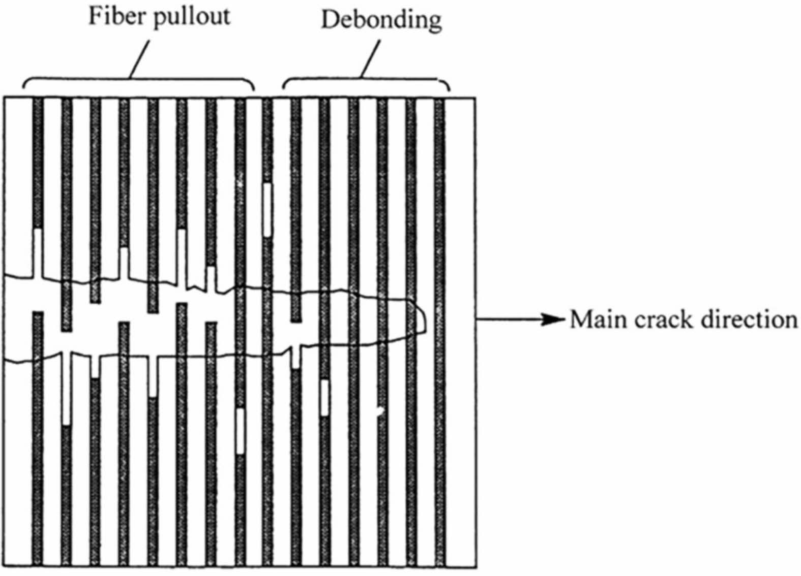
Since the fiber is the main load-bearing unit, the interface phase must have enough strength to act as a bridge between the matrix and fiber to achieve load transfer between the matrix and the fiber [16, 17]. From this point of view, weak interfacial bonding tends to cause interface debonding at lower stresses, making it difficult to transfer load effectively, so that the fiber can’t give full play to its reinforcing effect (Fig. 1), resulting in low mechanical properties of composites. In the case of strong interfacial bonding, the interfacial cannot adjust the stress distribution, and the local stress concentration will lead to low stress fracture of composites. Therefore, only when the interface bonding is moderate, the interface can play the role of transferring load and regulating stress at the same time, so as to improve the mechanical properties of the composite material well [18, 19].
Physical and chemical compatibility
For CMCs, their service conditions are generally high temperature environments, so their interface design should consider not only the interfacial bonding strength, but also the physical and chemical compatibility of the interface. On the one hand, the interface should be well matched with the thermal expansion coefficient of the fiber and matrix, which can relieve the interface residual stress caused by thermal expansion mismatch between fiber and matrix and improve the interface behavior between them [20, 21]. On the other hand, the interface should be chemically compatible with the fiber and matrix, i.e., the fiber-interface-matrix can coexist, and the chemical composition of the whole system is thermodynamically stable, or no interfacial chemical reactions that reduce strength and toughness during the molding and use [22, 23].
Prevent or inhibit oxidation
CMCs inevitably experiences high temperature environment during their preparation or use, especially their service environment, which generally is an oxidizing atmosphere [24]. However, the mutual diffusion between matrix and fiber at high temperatures and the erosion of the oxidizing atmosphere can substantially reduce the fiber properties [25]. Therefore, the interface should be able to play a protective role in the fiber under high temperature conditions. On the one hand, it can prevent or inhibit the atomic mutual diffusion and chemical reaction between the fiber and the matrix, and it can prevent or slow down the erosion of the oxidizing atmosphere, so as to improve the high temperature oxidation resistance of the fiber and even the composite [10, 25, 26].
|
Fig. 1 Partial toughening mechanism of fibers [17]. |
In CMCs, the fiber surface coating is the prerequisite to obtain the interfacial layer. Therefore, the preparation method of the fiber surface coating directly affects the phase composition, microstructure and interfacial bonding of the interfacial layer. Currently, the commonly used coating preparation methods are chemical vapor deposition (CVD), precursor infiltration pyrolysis (PIP), sol-gel and in situ synthesis.
CVD method is to transport several gases to the fiber surface where chemical reactions take place, and the reaction products are deposited on the fiber surface to form a coating [27]. The deposition effect of the interfacial phase prepared by this method is affected by the size of the preform, deposition rate, deposition temperature and other factors [28-30]. In general, the method has strong adaptability to the surface shape of the matrix material and can deposit uniform interfacial phases on the surface of complex shaped matrix, and can control the composition, thickness and structure of interfacial phase by adjusting the process parameters, which gives great flexibility in the design and control of the interfacial phases [31-33]. Therefore, CVD process is an effective method for preparing interfacial phases of CMCs. However, the CVD process has the disadvantages of low preparation efficiency and high energy consumption, so it is not suitable for the preparation of interfacial phases of large braids.
PIP method is to first impregnate the fibers with a precursor, then cross-link and cure the precursor to coat the fibers and obtain a coating on the fiber surface after high temperature cracking [34]. The method is simple and suitable for the preparation of 2D fiber braided surface coating. However, due to the differences in impregnation ability and wettability of the precursor, its suitability in 3D fiber braided parts is poor. Therefore, ultrasonic vibration and vacuuming are needed to improve the impregnation ability of the precursor in 3D fiber braided parts. Currently, this method is mainly applied to the preparation of PyC and SiC coatings on fiber surfaces [35]. However, the PIP process is accompanied by the escape of gas during the precursor cracking process, which causes the formation of defects such as micropores and microcracks inside the coating, making it difficult to obtain a uniform coating on the surface of the fibers and poor repeatability. Meanwhile, the SiC interfacial layer prepared by the PIP process can cause thermal stress damage and structural damage to the fibers, which makes the mechanical properties of the fibers seriously degraded [36]. Taguchi et al. [37] studied the effect of carbon interface prepared by PIP process and CVD process on mechanical properties of 2D SiC/SiC composites. The reinforcement used was a plain fabric of Hi-Nicalon fibers. The results showed that the carbon interface composites prepared by the PIP method underwent brittle fracture, and their fracture toughness and bending strength were lower than those of the carbon interface composites prepared by the CVD method.
Sol-gel method is to dissolve alkoxide or its mixture in solvent to impregnate fiber, and then the solution is "gelatinized" to form colloid (i.e. sol). After a certain period of time, the sol hydrolyzes into gel, which is heated by evaporation to remove the liquid phase and sintered into a coating at a certain temperature [38, 39]. The coating material that can be formed is nitride or oxide. Sol-gel method equipment process is simple and low cost; the coating with accurate composition and high purity can be obtained, and even amorphous coatings can be obtained by adjusting the purity of raw materials and controlling the reaction process [40]. Additionally, multi-layer composite coatings can be prepared by using different formulations in the cycle. In addition to the above advantages, the sol gel method also has a major problem, that is, the gel contains a lot of liquid phase, and the shrinkage of liquid phase after evaporation will form defects such as microcracks or pores in the coating, making it difficult to get uniform coating on the fiber surface. However, if properly controlled, porous interface phase can also be obtained by this method.
There are two main types of in situ synthesis methods: one is not to directly prepare a coating on the fiber surface, but to obtain an interfacial layer with a composition and microstructure different from that of the fiber and the matrix by diffusion of elements between the matrix and the fiber. In this process, a small amount of chemical reaction can enhance the bonding between the fiber and the matrix, while too much chemical reaction will lead to strong interfacial bonding, and the generation of brittle phases at high temperatures where the interfacial products can’t be effectively controlled will cause a serious decrease in the mechanical properties of the fiber [41]. The other is to prepare the coating on the fiber surface by in-situ reaction. The interface bonding of the coating prepared by this method is strong and also causes damage to the fiber, but the phenomenon can be mitigated by interfacial modulation.
Interface bonding strength is a bridge to construct the interface properties and macroscopic mechanical properties of CMCs composites, and also a wind vane to guide the preparation and process optimization of the interface phase of CMCs composites. At present, there are four main methods to measure the bonding strength of ceramic matrix interface: fiber pull-out length statistics, crack statistics, single fiber push-out and single fiber push-in.
Fracture pull-out fiber length statistics method
The statistical method of fiber length is the simplest method to evaluate the interfacial bonding strength. The interfacial bonding strength τ can be calculated according to equation (1) [42-44].

Where S0 and m represent the Weibull parameters for the in situ strength of fibers in CMCs, respectively, r is the fiber radius, and h is the statistical value of fiber pull-out length.
According to equation (1), the following problems are found in this method. First, the Weibull parameter of fiber in situ strength is difficult to test due to the difficulty of peeling the fibers of CMCs, which is generally replaced by the Weibull parameter of the original fiber strength, resulting in low accuracy of the assessed interfacial bond strength. Second, the statistical workload of the fracture fiber pull-out length was large, subjective and arbitrary, and the data accuracy was not high. Therefore, this method is generally used as a qualitative analysis method for interfacial bond strength.
Crack statistics method
The crack statistics method is generally applied to Minicomposites (Mini-composites), including the crack number statistical method and the statistical method of saturated crack spacing.
Crack number statistic method
The number of cracks statistic method is to load the bundle wire composites cyclically and calculate the interfacial bond strength using the width of the last loading-unloading return line before the failure of the bundle wire (δ∆) and the number of matrix cracks within the test span after failure (N), which is calculated by equation (2-4) [45-47].
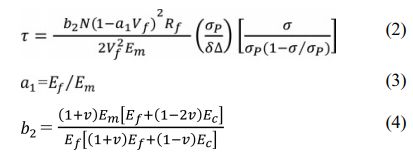
Where σP is the initial unloading stress, σ is the last loading-unloading cycle stress before filament failure, Rf is the fiber radius, Vf is the fiber volume fraction, Ef, Em, Ec are the fiber, matrix and filament composite modulus, respectively, and v is the Poisson's ratio (vf = vm = vc).
It can be found from the above process that the crack number statistic method is complicated and requires cyclic loading, and cyclic loading is required, and each loading-unloading process is somewhat random. Besides, the number of matrix crack is subjective, with a large workload and prone to the problem of omission.
Crack spacing statistic method
Similar to the crack number statistic method, the crack spacing statistic method also calculates the interfacial bonding strength by counting the cracks after the failure of the Minicomposites, but the process is relatively simple and can be loaded directly without the use of cyclic loading. The interfacial bonding strength is calculated by counting the spatial distance (ls) of matrix crack saturation, which is calculated by equation (5) [45, 46].
Where σs is the stress at matrix crack saturation, which is extracted by load-displacement curve, Rf is the fiber radius, Vf is the fiber volume fraction, Ef, Em are the fiber and matrix modulus, respectively.
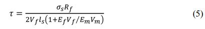
Although the loading process of the crack spacing statistic method is relatively simple, it is necessary to read the load-displacement curve (Fig. 2) of stress at matrix crack saturation. In the specific implementation process, there are relatively subjective factors in the reading of crack saturation region. Therefore, the crack spacing statistic method is similar to the crack number statistic method, which also suffers from the problems of subjectivity and inaccuracy.
Single fiber push-out method
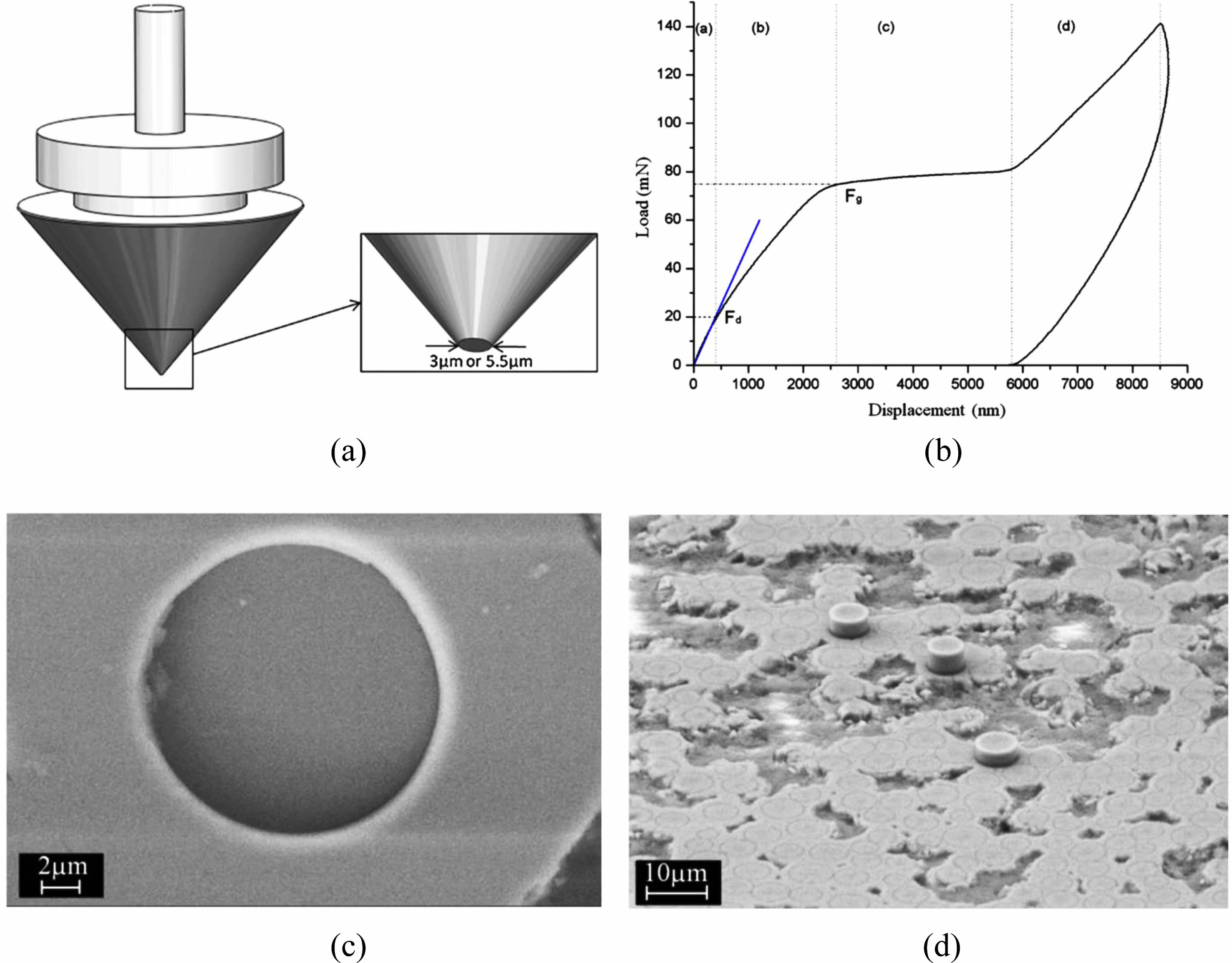
Compared to the above two methods, the single-fiber push-out method is an accurate method to measure the interfacial strength of composites [48, 49], i.e., the composite thin sheets with thickness less than 100 μm are prepared first, then the single fiber is loaded using nano indentation (flat head), and the load-displacement curve is recorded (Fig. 3). Finally, the interface bonding strength of the composite is calculated according to equation (6) [48]

Where Fg is the debonding load, Rf is the fiber radius, and lf is the sample thickness.
The single fiber push-out test is applicable for composite materials with various fiber braided structures, only need to ensure that the test sheet fiber axially parallel to the indenter loading direction. This method is simple to calculate, the parameters can be accurately read, and the interfacial bond strength of composites can be accurately measured. However, it has two disadvantages: first, the high hardness and brittleness of CMCs make it difficult to prepare thin samples containing several intact fibers; second, the mechanical environment of the composites is easily damaged during the grinding and preparation of thin sheets, resulting in changes in interfacial bond strength and even interfacial debonding, which affects test results. The above two disadvantages make the application of fiber push-out method less and less.
Single fiber push-in
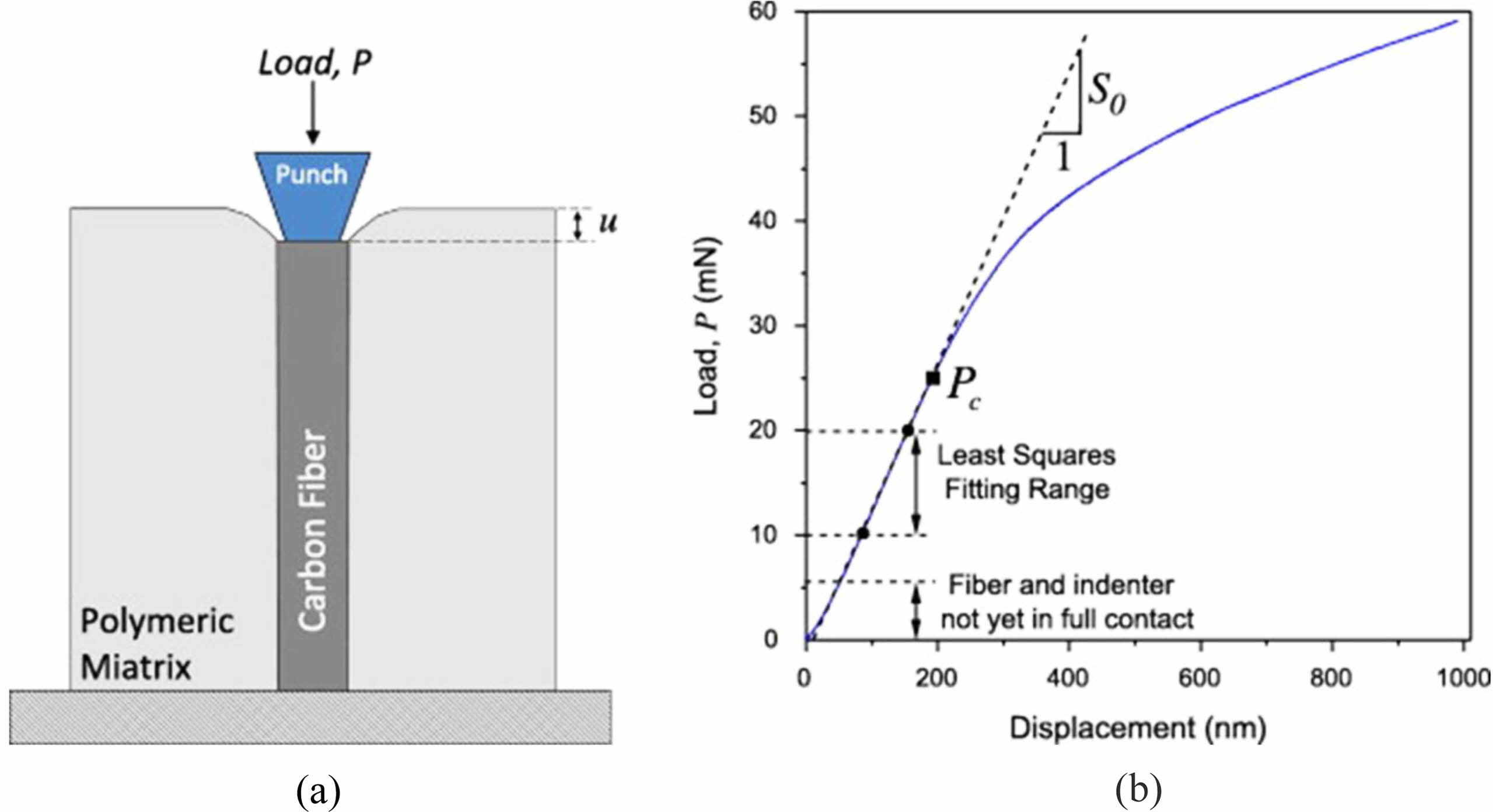
The single-fiber jacking method is implemented by first taking a sample in the composite material so that the fiber cross section is parallel to the sample surface, polishing it and then loading the single fiber using a flat indenter (Fig. 4(a)), and recording the load-displacement curve. Typical load-displacement curves show an "S" shape (Fig. 9(b)), where the initial segment of the curve corresponds to the contact process between the indenter and the fiber, the middle segment (slope S0) corresponds to the elastic deformation of the fiber, and the later segment corresponds to the debonding process at the fiber/matrix interface [50]. According to the Shear-lag model, the interfacial bonding strength of composites can be calculated [10-19], and the calculation formula is Equation (7).

Where Rf is the fiber radius, Pc is the critical load, characterizing the onset of interfacial debonding (Fig. 9(b)), and Ef is the fiber modulus.
Through the above testing process, it can be found that the single fiber push-in method can accurately measure the interfacial bonding strength, avoid the problem of influencing the interfacial mechanical environment during the preparation of small thickness samples compared to the single fiber push-out method, and the implementation process is simple. The above advantages make the single-fiber push-in method a common tool for interfacial bonding strength measurement of CMCs. Liu et al. [51-53] carried out a large number of studies on the interfacial bonding strength of CMCs using the single-fiber push-in method.
|
Fig. 2 Typical features of the load-deformation curve of Minicomposites [45]. |
|
Fig. 3 (a) Schematic drawing of flat punch diamond indenter used for the single fibre push-out tests; (b) Typical load-displacement push-out test curve; Scanning electron micrographs of the (c) frontside surface and (d) backside surface of a SiC/SiC minicomposite sample after push-out test using a flat punch indenter [48]. |
|
Fig. 4 (a) Schematic of the fiber push-in test; (b) Representative load-displacement push-in test curve [50]. |
|
Fig. 5 Crystallinity gradient BN interfacial phase diagram [59]. |
|
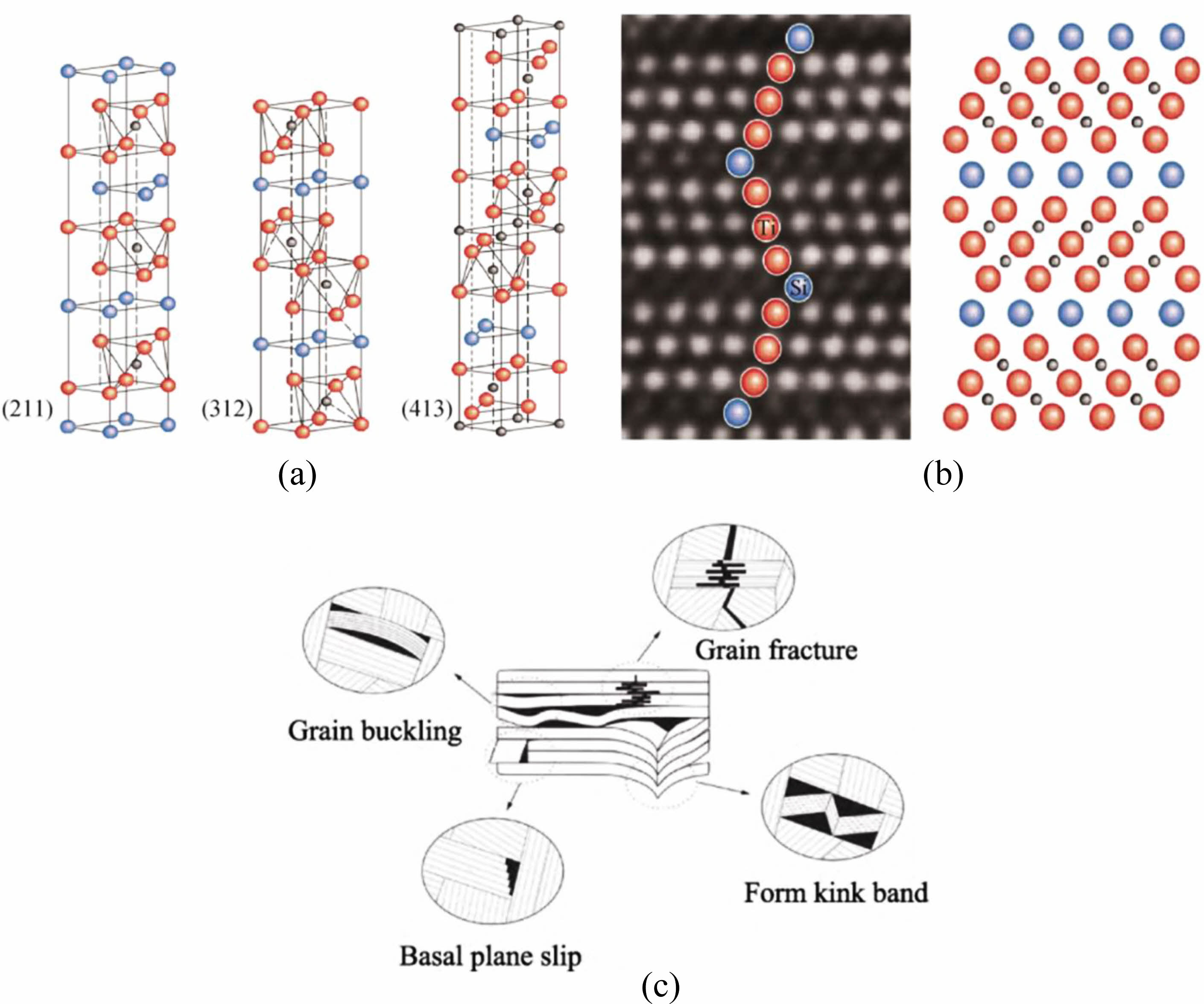
Fig. 6 Crystal structure (a), high-resolution transmission electron micrograph (b) and microzone deformation mechanism (c) of MAX phase [86, 87]. |
PyC interface
PyC is considered to be the most ideal interfacial phase material for modulating the mechanical properties of CMCs, but the PyC interface has poor oxidation resistance and starts to oxidize at about 500 °C to generate gaseous oxides, which makes the interfacial phase lose its interfacial modulation and protection function. In order to improve the oxidation resistance of PyC interfacial phase, doping PyC interfacial phase was proposed. At present, the main PyC dopants reported are B and SiC. The doping of B can not only improve the crystallinity of carbon, but also generate flowing B2O3 glass phase to cover the active part of carbon and hinder the oxidation of carbon at the medium temperature (800±200 ℃) [54]. Jacques et al. [55] showed that the oxidation mass loss of the B-doped PyC interface was significantly reduced in dry air at 700 ℃ and 800 ℃, and the oxidation resistance of PyC was significantly improved. Unlike PyC(B), the doping of PyC by SiC nanocrystals does not change the crystallinity and microstructure of PyC, but the amount of doping has a great influence on the modification effect. Wang et al. [56] found by doping SiC in PyC that the room temperature tensile strength of SiC/PyC(SiC)/SiC composites increased by 51% compared to SiC/PyC/SiC when the doping amount was appropriate, and the ductile fracture characteristics were obvious. However, when the doping amount was too much, the interfacial phase brittleness of PyC increased, and the room temperature tensile strength of SiC/PyC(SiC)/SiC composites decreased by 14.7% compared with SiC/PyC/SiC, and the ductile fracture characteristics are also significantly weakened.
BN interface
BN has a layered crystal structure similar to PyC, which can repair fiber surface defects and deflect cracks, significantly improve the mechanical properties of CMCs, and has better oxidation properties than PyC [57]. Therefore, BN is a well-studied antioxidant interfacial phase for CMCs. However, BN interfacial phase has a pair of contradictory factors. The low crystallinity of BN interfacial phase and the frequent presence of impurities such as C and O can reduce the high temperature stability of BN interfacial phase. However, BN with low crystallinity has high binding ability to fibers and is not easy to debond, which is in line with the layered structure interface design concept. To reconcile this contradiction and improve the oxidation resistance of BN, researchers have explored four improvement approaches.
First, BN homogeneous double coating: the inner sublayer uses a low crystallinity BN coating so that it retains its characteristics of strong bonding to the fiber. The outer sublayer uses an improved high crystallinity BN coating to increase its resistance to oxidation. Rebillat et al. [58] used this method to prepare CMCs with internal cracks deflected within the double coating to meet the interfacial phase design requirements of the layered structure.
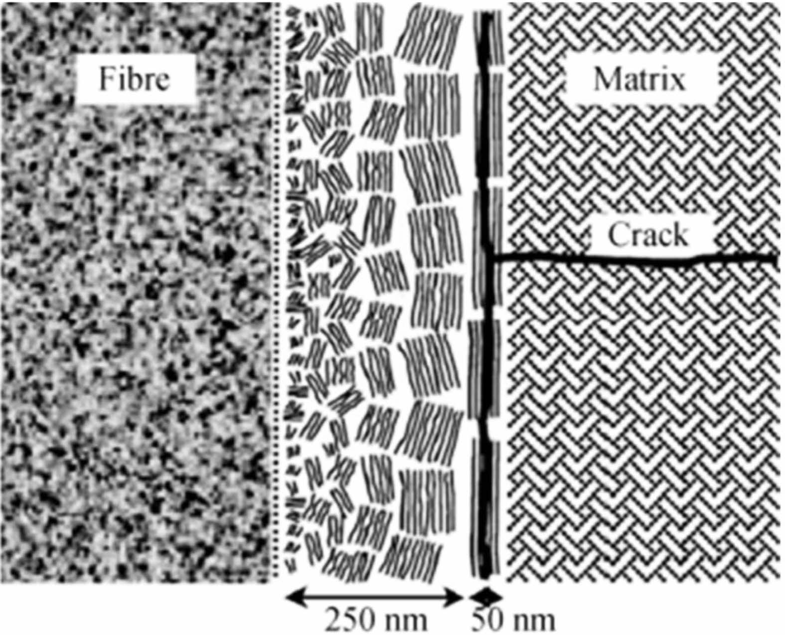
Second, crystallinity gradient BN coating: using the temperature gradient CVD method, a crystallinity gradient BN interfacial coating is prepared on the fiber surface, as shown in Fig. 5, from inside to outside, BN gradually changes from isotropic to anisotropic, and the purpose is also to form a microstructure with tight bonding against the fiber side and good oxidation resistance against the substrate side. Jacques et al. [59] used this method to prepare CMCs with static tensile lifetimes 133 and 37 times of SiC/PyC/SiC in dry and moist air at 700 ℃, respectively.
Third, using new BN precursors, Jacques et al. [60] prepared the BN interfacial phase of CMCs by using halogen-free organometallic precursor, whose interfacial bonding strength was significantly improved and interface shear stress was up to 230 MPa.
Fourth, doped BN interfacial phase, such as Si doped BN interfacial phase. Moore [61] et al. found by Si-doped BN that the oxidation rate of Si-doped BN was 2-3 orders of magnitude lower than that of undoped BN in oxygen at 1200 °C or air at 1500 °C. However, the process temperature of Si-doped BN is as high as 1400 °C [62], which places high demands on the high temperature resistance of SiC fibers. Meanwhile, the Si-doped BN is amorphous, which deviates from the design concept of interfacial phase of the layered structure. Therefore, Morscher et al. [63] proposed the idea of double-layer interface phase design with an inner layer of highly crystalline BN as a mechanically regulated layer and an outer layer of Si-doped BN as an antioxidant layer.
Carbide coating
The temperature resistance and oxidation resistance of the carbide coating represented by SiC are better than BN, which adapts to the development of oxidation resistant interface layer. CVD is a typical method for preparing SiC coatings, which can significantly improve the mechanical and oxidation resistance properties of SiC/SiC composites at suitable thickness [64]. However, SiC deposition tends to cause local protrusions, which become a source of stress concentration and cause a significant decrease in fiber strength. This problem can be avoided by using low concentration ceramic precursor solution immersion cracking to prepare SiC coating [65].
Carbides are hard and brittle substances with no mechanism for deflecting cracks by themselves, and are not used too much as an interface phase alone. To introduce the crack deflection mechanism, researchers have proposed methods to prepare into porous coatings, multilayer carbide structures, or alternate coating structures.
(X-Y)n composite interface
The above methods of optimizing the interfacial phases of CMCs are all carried out on the basis of homogeneous interfacial phases. The appearance of (X-Y)n type composite interfacial phase extends the concept of interfacial phase of layered structure from monolayer interfacial phase to multilayer interfacial phase and the scale of regulation from atomic scale to micro-nano scale, which makes the properties of CMCs more highly tunable. The currently reported interfacial phases of the composites are mainly in the form of alternating layered crystal structure sublayers and self-healing sublayers, specifically (PyC-SiC)n, (BN-SiC)n, (PyC-TiC)n, etc.
Compared with the pure PyC interfacial phase, the (PyC-SiC)n interfacial phase does not significantly improve the room temperature mechanical properties of the CMCs, but forms a stronger fiber-matrix interfacial bond, which deflects the cracks within the PyC sublayer. As the crack extension path increases, the oxygen diffusion path also increases, which slows down the progress of fiber erosion by oxygen [66]. Therefore, the high-temperature static and dynamic lifetimes of the (PyC-SiC)n interfacial phase modified CMCs are longer than those of the pure PyC interfacial phase modified CMSs. Bertrand et al. [67], by implementing mechanical experiments on SiC/(PyC-SiC)10/SiC composites and SiC/PyC/SiC composites, found that the tensile fatigue life (load 120 MPa) of 2D-SiC/(PyC-SiC)10/SiC composites at 600 °C and 1200 °C was 3.97 and 3.37 times of that of 2D-sic/PyC/SiC composites. The (BN-SiC)n composite interfacial phase contains BN, which can heal cracks in the medium temperature range and has better oxidation resistance than the (PyC-SiC)n interfacial phase [66, 68]. (PyC-TiC)n is different from the above composite interfacial phases, its oxidation resistance mechanism is that each sublayer contains a nano-TiC-reinforced PyC layer, which forms a stronger fiber-matrix interfacial bond, thus preventing the diffusion of oxygen and protecting the SiC fibers. As a result, the static tensile life of its modified CMCs in air at 700 °C (>300 h) is much higher than that of the pure PyC interfacial phase modifiedCMCs (20 h) [69].
Refractory oxide interface
With the increasing requirements for oxidation resistance and service life of CMCs, the need for oxidation resistant interface coatings has become more and more urgent. Therefore, oxide ceramic coatings with high refractoriness and low oxygen diffusion coefficient have become a research hotspot in recent years. The coating composition includes ZrO2 [70], Al2O3 [71], Al2O3-SiO2 [72], MgO-SiO2 [73], ZrO2-SiO2 [74], etc. The preparation techniques of these coatings are mainly CVD method and sol-gel method.
ZrO2 is the most studied oxide interfacial coating. It is worth noting that: first, the effect of oxygen partial pressure on nucleation and structure of ZrO2 should be paid special attention when preparing ZrO2 by CVD method [75]. Second, in the process of sol-gel preparation of ZrO2, the influence of the physical state of SiC fiber surface on the morphology and stability of ZrO2 cannot be ignored [76-78]. When ZrO2 is combined with SiC fiber, it is very easy to form Zr-O-Si bond, so that the fibers and interfaces form strong bond [78], which can be improved by ZrO2 homogeneous multilayer interfacial phase. Utkin et al. [79, 80] modified SiC/SiC composites by this method showed non-brittle fracture characteristics and obvious fiber pulling out phenomenon. Third, multiple coatings with low concentration sol is necessary to obtain uniform and dense ZrO2 coating. For composite phase coating, the uniformity of composite phase sol has a great influence on the uniformity of composition and microstructure of the coating, which in turn affects the oxidation resistance [81]. Studies have shown that no matter which method is used to prepare ZrO2 coating, the strength of SiC fiber is basically not damaged [78]. When the ZrO2 coating reaches the ideal structure, the SiC/SiC composite fiber pulls out obviously, showing the same or better oxidation resistance and damage life than BN coating composite [75].
Current studies on ZrO2 coatings have also found that the mechanism of ZrO2 coating is closely related to its phase transition process. However, the phase transition is detrimental to the coating integrity. To improve this problem, Baklanova et al. [81] proposed that the phase composition, degree of phase transformation, and morphology of the ZrO2 coating need to be precisely controlled before the composite matrix, so as to obtain the ideal dense coating under compressive stress without debonding within the layer.
New interface
Hot end components in aero engines often face complex and extreme service environments, including ultra-high temperature, thermal shock, water vapor corrosion, etc. In this harsh environment, the degradation of the organization of the conventional interfacial phase is one of the important reasons for the degradation of the performance of CMCs composites. In order to meet the demand for interfacial phases in CMCs, some researchers have started to explore new interfacial phases that can replace the conventional interfaces such as BN and PyC. Currently, the proposed new interfacial phases mainly include Y2Si2O7 [82], LaPO4 [83], CaWO4 [84], AlPO4 [85] and MAX phase [86].
At present, more research is conducted on the MAX phase, which has a layer structure similar to PyC and h-BN, as well as a high c/a value and low interlaminar shear stress, and usually shows micro-regional plastic deformation such as slip, buckling and kinking under the applied stress (as shown in Fig. 6), so the MAX phase can be used as a weak interfacial layer, which can effectively deflect cracks and consume a large amount of fracture energy [86-87]. Meanwhile, the MAX phase has higher interlayer bonding strength compared with PyC and h-BN, which can effectively improve the load transfer efficiency. Therefore, the MAX phase can be regarded as a "strong" weak interface, which can help to achieve the synergistic improvement of strength and toughness of CMCs.
Regarding the MAX phase, a lot of research work on the preparation of MAX phase coating has been carried out at home and abroad. Li et al. [88] used high-temperature molten salt as a medium to generate a TiC/TiAlC composite interfacial layer on the surface of carbon fiber cloth using the in situ reaction between C and Ti and Al. The interfacial layer can play a good antioxidant role below 800 °C, but at temperatures above 1000 °C, the interfacial layer will be rapidly oxidized and lose the protective effect on the fiber. Jacques et al. [89, 90] of the University of Lyon, France, used CVD for the preparation of MAX phase coatings, which was accompanied by the formation of many by-products during the preparation process. It can be seen that the preparation process of MAX phase is still immature compared with PyC and h-BN, and further optimization is needed to achieve engineering applications.
Compared with conventional interfacial phases such as PyC and BN, the new interfacial phases show significant potential for use as antioxidant interfacial phases [91-93], but there are some problems in terms of thermal expansion coefficient matching, high temperature stability and preparation methods [94, 95]. Therefore, a more in-depth study of the antioxidant mechanism of fiber-reinforced ceramic matrix composites containing new interfacial phases is needed.
In summary, the interfacial phase is one of the key factors affecting the performance of CMCs. In order to meet the development of CMCs, the study of interfacial phase of CMCs has undergone a change from the merely pursuit of mechanical properties to the combination of antioxidant and mechanical properties, and the form of interfacial phase has also changed from single-component to complex multi-component, single-layer form to multi-layer combination form, and the types of materials of the studied interfacial phase have increased year by year. However, in the face of the growing demand for CMCs in various fields, there is still a lot of work to be done in the interface phase of CMCs in the future.
In the aspect of CMCs interfacial phase preparation, only CVD process can meet the practical engineering application at present. Although other preparation processes are relatively simple and some can be used to construct special interfacial phases, it is difficult to obtain uniform coating on the surface of the fiber. Researchers can further explore the technical potential of the existing interfacial phase preparation processes (such as Sol-Gel process) to solve the defects in uniformity and density of the prepared interfacial phase. At the same time, a combination of the existing preparation process can be considered to give full play to the advantages of different preparation methods.
In the aspect of CMCs interface phase strength testing, the current characterization and evaluation techniques still suffer from difficulties in sample preparation and data dispersion. To solve this problem, more perfect testing methods should be built to minimize the error between experimental data and actual strength.
In terms of the development of CMCs interfacial phases, complex multi-component forms, multi-layer combination forms and new interfacial phases can give CMCs better mechanical properties and oxidation resistance compared with traditional interfacial phases. However, most of the new interfacial phases (such as MAX) have some problems in thermal expansion coefficient matching, high temperature stability and preparation methods. Therefore, future research on new interface phases should focus on: 1) Different new interfacial phases should be selected according to different fiber and ceramic matrix; 2) The preparation method should be optimized to prepare continuous, uniform and dense interfacial phases without damaging the fiber strength while improving the overall performance of CMCs; 3) Further research is needed on the mechanism of CMCs containing new interfacial phases.
- 1. R. Naslain, Compos. Sci. Technol. 64[2] (2004) 155-170.
-

- 2. N.A. Nasiri, N. Patya, N. Ni, D.D. Jayaseelan, and W.E. Lee, J. Eur. Ceram. Soc. 36[14] (2016) 3293-3302.
-
- 3. H. Liu, J.H. Yang, Y.R. Zhou, X.X. Liu, Z. Qi, and J. Jiao, J. Mater. Eng. 46[11] (2018) 1-12.
- 4. X.W. Yin, L.F. Cheng, L.T. Zhang, N. Travitzky, and P. Greil, Int. Mater. Rev. 62[3] (2017) 117-172.
-
- 5. W. Krenkel, and F. Berndt, Mater. Sci. Eng. 412[1] (2005) 177-181.
-
- 6. Q.S. Ma, H.T. Liu, Y. Pan, and W.D. Liu, J. Inorg. Mater. 28[3] (2013) 247-255.
-
- 7. H.B. Guo, B. Wang, G.J. Jiao, and Y.S. Liu, J. Mater. Eng. 17[5] (2013) 83-88.
- 8. J.H. Miller, P. Liaw, and J.D. Landes, Mater. Sci. Eng. A 317[49] (2001) 49-58.
-
- 9. R. Naslain, O. Dugne, and A. Guette, J. Am. Ceram. Soc. 74[10] (1991) 2482-2488.
-
- 10. R.R. Naslain, Composites Part A 29[9-10] (1998) 1145-1155.
-
- 11. Y.F. Zhang, J.K. Guo, P.N. Zhu, H.M. Yang, and S.Z. Huang, J. Inorg. Mater. 10[2] (1995) 231-235.
- 12. H.P. Qiu, M. Sun, H.Y. Ding, and L.J. Han, Bull. Chin. Ceram. Soc. 1 (2006) 63-65.
- 13. Q. Zhou, S.M. Dong, Y.S. Ding, X.Y. Zhang, Z. Wang, Z.R. Huang, and D.L. Jiang, J. Inorg. Mater. 22[6] (2007) 1142-1146.
-
- 14. G.F. Lu, J. Chin. Ceram. Soc. 40[8] (2012) 1169-1173.
- 15. L. Longbiao, Compos. Interface. 27[6] (2020) 551-557.
-
- 16. J. Zhang, Y. Liu, L. Cheng, H. Zhao, and J. Wang, J. Eur. Ceram. Soc. 39[15] (2019) 4609-4616.
-
- 17. K.K. Chawla, J. Eur. Ceram. Soc. 28[2] (2008) 447-453.
-
- 18. S. Daggumati, A. Sharma, A. Kasera, and N. Upadhyay, J. Mater. Eng. Perform. 29[4] (2020) 2049-2060.
-
- 19. L. Li, Ann. Mater. Sci. Eng. 2020 (2020) 1-17.
- 20. D. Congalton, Fire Mater. 23[5] (1999) 223-226.
-
- 21. F.W. Zok, J. Am. Ceram. Soc. 89[11] (2006) 3309-3324.
-
- 22. X.W. Yin, L.F. Cheng, L.T. Zhang, N. Travitzky, and P. Greil, Int. Mater. Rev. 62[3] (2017) 117-172.
-
- 23. K. Chawla, C. Coffin, and Z. Xu, Int. Mater. Rev. 45[5] (2000) 165-189.
-
- 24. V. Sabelkin, S. Mall, T.S. Cook, and J. Fish, J. Compos. Mater. 50[16] (2016) 2145-2153.
-
- 25. Q. Ma and L. Cai, J. Adv. Ceram. 6[4] (2017) 360-367.
-
- 26. L. Li, Ceram. Int. 46[17] (2020) 27031-27045.
-
- 27. S. Jacques, H. Vincent, C. Vincent, A. Lopez-Marure, and Bouix, J. Solid State Chem. 162[2] (2001) 358-363.
-
- 28. S. Jacques, A. Lopez-Marure, C. Vincent, H. Vincent, and J. Bouix, J. Eur. Ceram. Soc. 20[12] (2000) 1929-1938.
-
- 29. H. Hannache, J.M. Quenisset, R. Naslain, and L. Heraud, J. Mater. Sci. 19[1] (1984) 202-212.
-
- 30. C.Y. Hu and J.H. Li, J. Rare Met. 25[5] (2001) 364-368.
- 31. H.P. Zhang and A.D. Tang, Carbon Tech. 23[5] (2004) 1-5.
- 32. Y.Z. Zhu, Z.R. Huang, S.M. Dong, M. Yuan, and D.L. Jiang, New Carbon Mater. 22[4] (2007) 327-331.
-
- 33. Y. Xiang, W. Li, S. Wang, and Z.H. Chen, Mater. Sci. Eng. 558 (2012) 451-455.
-
- 34. Y.Z. Zhu, Z.R. Huang, S.M. Dong, M. Yuan, and D.L. Jiang, Ceram. Int. 34[5] (2008) 1201-1205.
- 35. H.T. Liu, L.W. Yang, X. Sun, H.F. Cheng, C.Y. Wang, W.G. Mao, and J.M. Molina-Aldareguia, Carbon 109 (2016) 435-443.
-
- 36. D. Ding, W. Zhou, F. Luo, and M.L. Chen, Ceram. Int. 38[5] (2012) 3929-3934.
-
- 37. T. Taguchi, N. Igawa, R. Yamada, and S. Jitsukawa, J. Phys. Chem. Solids 66[2-4] (2005) 576-580.
-
- 38. R.A. Caruso, J.H. Schattka, and A. Greiner, Adv. Mater. 13[20] (2001) 1577-1579.
-
- 39. M.K. Cinibulk and R.S. Hay, J. Am. Ceram. Soc. 79[5] (1996) 1233-1246.
-
- 40. V. Liedtke, I. Huertas Olivares, M. Langer, and Y.F. Haruvy, J. Eur. Ceram. Soc. 27[2-3] (2007) 1267-1272.
-
- 41. S.M. Jeng, J.M. Yang, and J.A. Graves, J. Mater. Res. 8[4] (1993) 905-916.
-
- 42. I.J. Davies, T. Ishikawa, M.Shibuya, T. Hirokawa, and J. Gotoh, Composites Part A 30[4] (1999) 587-591.
-
- 43. I.J. Davies, T. Ogasawara, and T. Ishikawa, J. Eur. Ceram. Soc. 25[5] (2005) 599-604.
-
- 44. J. Brandstetter, H. Peterlik, K. Kromp, and R. Weiss, Compos. Sci. Technol. 63[5] (2003) 653-660.
-
- 45. S. Bertrand, P. Forio, R. Pailler, and J. Lamon, J. Am. Ceram. Soc. 82[9] (1999) 2465-2473.
-
- 46. C. Sauder, A. Brusson, and J. Lamon, Int. J. Appl. Ceram. Technol. 7[3] (2010) 291-303.
-
- 47. G.N. Morscher and J. Martinez-Fernandez, J. Am. Ceram. Soc. 82[1] (1999) 145-155.
-
- 48. E. Buet, C. Sauder, D. Sornin, S. Poissonnet, J.-N. Rouzaud, and C. Vix-Guterld, J. Eur. Ceram. Soc. 34[2] (2014) 179-188.
-
- 49. W.M. Mueller, J. Moosburger-Will, M.G.R. Sause, and S. Horn, J. Eur. Ceram. Soc. 33[2] (2013) 441-451.
-
- 50. M. Rodriguez, J.M. Molina-Aldareguia, C. Gonzalez, and J. LLorca, Compos. Sci. Technol. 72[15] (2012) 1924-1932.
-
- 51. H.T. Liu, L.W. Yang, X. Sun, H.F. Cheng, C.Y. Wang, W.G. Mao, and J.M. Molina-Aldareguia, Carbon 109 (2016) 435-443.
-
- 52. H.T. Liu, L.W. Yang, S. Han, H.F. Cheng, W.G. Mao, and J.M. Molina-Aldareguia, J. Eur. Ceram. Soc. 37[3] (2017) 883-890.
-
- 53. L.W. Yang, J.Y. Wang, H.T. Liu, R. Jiang, and H.F. Cheng, Composites Part B 119 (2017) 79-89.
-
- 54. D.W. McKee, C.L. Spiro, and E.J. Lamby, Carbon 22[6] (1984) 507-511.
-
- 55. S. Jacques, A. Guette, X. Bourrat, F. Langlais, C. Guimon, and C. Labrugere, Carbon 34[9] (1996) 1135-1143.
-
- 56. H.R. Wang, Z.K. Chen, R.Q. Zhang, Z.B. He, Y. Wu, Y.H. Chen, and X. Xiong, Ceram. Int. 46[14] (2020) 22297-22306.
-
- 57. L.H. Cai, Q.S. Ma, H.T. Liiu, and R.J. Liu, Bull. Chin. Ceram. Soc. 32[5] (2013) 878-883, 889.
- 58. F. Rebillat, J. Lamon, and A. Guette, Acta Mater. 48[18] (2000) 4609-4618.
-
- 59. S. Jacques, A Lopez-Marure, C. Vincent, H. Vincent, and J. Bouix, J. Eur. Ceram. Soc. 20[12] (2000) 1929-1938.
-
- 60. S. Jacques, B. Bonnetot, M.P. Berthet, and H. Vincent, Ceram. Eng. Sci. Proc. 25[4] (2008) 123-128.
- 61. A.W. Moore, H. Sayir, S.C. Fanner, and G.N. Morscher, Ceram. Eng. Sci. Proc. 16[4] (1995) 409-416.
-
- 62. G.N. Morscher and J.D. Cawley, J. Eur. Ceram. Soc. 22[14-15] (2002) 2777-2787.
-
- 63. G.N. Morscher, Ceram. Eng. Sci. Proc. 18[3] (1997) 737-745.
- 64. Y.M. Qin, C.X. Liu, C. Zheng, B. Chen, J. Zhang, S.L. Feng, H.F. Huang, and X.Q. Li, Corros. Sci. 204 (2022) 110411.
-
- 65. Y.Q. Wang, Z.M. Wang, J.Y. Yang, F.Q. Zhang, and B.L. Zhou, Compos. Manuf. 6[2] (1995) 103-106.
-
- 66. S. Bertrand, R. Pailler, and J. Lamon, J. Am. Ceram. Soc. 84[4] (2001) 787-794.
-
- 67. S. Bertrand, F. Germain, R. Pailler, and J. Lamon, Adv. Compos. Lett. 8[6] (1999) 1-7.
-
- 68. S. Bertrand, O. Boisron, R. Pailler, J. Lamon, and R. Naslain, Key Eng. Mater. 164-165 (1999) 357-360.
-
- 69. O. Rapaud, S. Jacques, H. Di-Murro, H. Vincent, M.P. Berthet, and J. Bouix, J. Mater. Sci. 39[1] (2004) 173-180.
-
- 70. H. Li, G.N. Morscher, J. Lee, and W.Y. Lee, J. Am. Ceram. Soc. 87[9] (2004) 1726-1733.
-
- 71. S. Parola, M. Verdenelli, C. Sigala, J.P. Scharff, K. Velez, C. Veytizou, and J.F. Quinson, J. Sol-Gel Sci. Technol. 26[1] (2003) 803-806.
-
- 72. M. Verdenelli, S. Parola, F. Chassagneux, J.M. Letoffe, H. Vincent, J.P. Scharf, and J. Bouix, J. Eur. Ceram. Soc. 23[8] (2003) 1207-1213.
-
- 73. N. Igawa, T. Taguchi, R. Yamada, Y. Ishi, and S. Jitsukawa, J. Nucl. Mater. 367-370 (2007) 725-729.
-
- 74. W.Y. Lee, E. Lara-Curzio, and K.L. More, J. Am. Ceram. Soc. 81[3] (1998) 717-720.
-
- 75. H. Li, G.N. Morscher, J. Lee, and W.Y. Lee, J. Am. Ceram. Soc. 87[9] (2004) 1726-1733.
-
- 76. N.I. Baklanova, B.A. Kolesov, and T.M. Zima, J. Eur. Ceram. Soc. 27[1] (2007) 165-171.
-
- 77. N.1. Baklanova, B.N. Zaitsev, and A.T. Titov, J. Eur. Ceram. Soc. 27[6] (2007) 2503-2511.
-
- 78. N.1.Baklanova, O.I. Kiselyova, A.T. Titov, and T.M. Zima, J. Eur. Ceram. Soc. 28[8] (2008) 1687-1696.
-
- 79. A.V. Utkin, A.A. Matvienko, A.T. Titov, and N.I. Baklanova, Inorg. Mater. 47[10] (2011) 1066-1071.
-
- 80. A.V. Utkin, A.A. Matvienko, A.T. Titov, and N.I. Baklanova, Surf. Coat. Technol. 205[8-9] (2011) 2724-2729.
-
- 81. N.1. Baklanov, A.T. Titov, A.I. Boronin, and S.V. Kosheev, J. Eur. Ceram. Soc. 26[9] (2006) 1725-1736.
-
- 82. Y. Xu, X.X. Hu, F.F. Xu, and K.W. Li, Ceram. Int. 43[8] (2017) 5847-5855.
-
- 83. Y. Hikichi and T. Nomura, J. Am. Ceram. Soc. 70[10] (1987) C252-C253.
-
- 84. R.M. Hazen, L.W. Finger, and J.W.E. Mariathasan, J. Phys. Chem. Solids. 46[2] (1985) 253-263.
-
- 85. Y.H. Bao and P.S. Nicholson, J. Am. Ceram. Soc. 89[2] (2010) 465-470.
-
- 86. M.W. Barsoum and T. EI-Raghy, Am. Sci. 89[4] (2001) 334-344.
- 87. Y.Z Ma, X.W. Yin, X.M. Fan, P.F. Ju, and X.L. Dang, Mat. Sci. Eng. A 712 (2018) 397-405.
-
- 88. M. Li, K. Wang, J. Wang, D.W. Long, Y.Q. Liang, L. He, F. Huang, S.Y. Du, and Q. Huang, J. Am. Ceram. Soc. 101[11] (2018) 5269-5280.
-
- 89. H. Fakih, S. Jacques, O. Dezellus, M.P. Berthet, F. Bosselet, M. Sacerdote-Peronnet, and J.C. Viala, J. Phase Equilib. Diffus. 29[3] (2008) 239-246.
-
- 90. S. Jacques, H. Fakih, and J.C. Viala, Thin Solid Films 518[18] (2010) 5071-5077.
-
- 91. K.A. Keller, T.I. Mah, T.A. Parthasarathy, E.E. Boakye, P. Mogilevsky, and M.K. Cinibulk, J. Am. Ceram. Soc. 86[2] (2003) 325-332.
-
- 92. E.E. Boakye, P. Mogilevsky, T.A. Parthasarathy, K.A. Keller, R.S. Hay, and M.K. Cinibulk, J. Am. Ceram. Soc. 99[2] (2015) 415-423.
-
- 93. P. Mogilevsky, T.A. Parthasarathy, and M.D. Petry, Acta Mater. 52[19] (2004) 5529-5537.
-
- 94. B.B. Wu, N. Ni, X.F. Zhao, X.H. Fan, P. Xiao, and F.W. Guo 40[8] (2020) 2801-2810.
- 95. B.B. Wu, N. Ni, X.H. Fan, X.F. Zhao, F.W. Guo, Q. Ding, and P. Xiao, Ceram. Int. 47[2] (2021) 1693-1703.
-
 This Article
-
2023; 24(2): 379-389
Published on Apr 30, 2023
- 10.36410/jcpr.2023.24.2.379
- Received on Jul 11, 2022
- Revised on Nov 23, 2022
- Accepted on Dec 20, 2022
Services
- Abstract
introduction
interface design concept of cmcs
interface preparation method of cmcs
interface bonding strength test method of cmcs
research status interface phase optimization of cmcs
conclusions and prospects
- References
- Full Text PDF
Shared
Correspondence to
- Yantao Gao
-
School of Textiles and Fashion, Shanghai University of Engineering Science, Shanghai 201620, China
Tel : 18217155467 Fax: 02167791486 - E-mail: gaoyantao@sues.edu.cn
Clean-Energy Research Institute(CRI), Hanyang University, 222, Wangsimni-ro, Seongdong-gu, Seoul, 04763, Korea
E-mail: jcpr@hanyang.ac.kr