


- Improved temperature stability of Ba0.5Sr0.5TiO3/ZnAl2O4 ceramics by controlling microstructure with sintering behavior
Yuze Xuea, Mingwei Zhanga,*, Le Xinb, Luchao Rena, Panpan Lva, Hang Zhana, Jing Hea and Jiwei Zhaic
aSchool of Materials Science and Engineering, Shandong University of Technology, Zibo 255049, Shandong, People’s Republic of China
bPrimary Education, Zibo Normal College, Zibo 255130, Shandong, People’s Republic of China
cSchool of Materials Science and Engineering, Tongji University, Shanghai 201804, Shanghai, People’s Republic of ChinaThis article is an open access article distributed under the terms of the Creative Commons Attribution Non-Commercial License (http://creativecommons.org/licenses/by-nc/4.0) which permits unrestricted non-commercial use, distribution, and reproduction in any medium, provided the original work is properly cited.
0.2ZnAl2O4/0.8Ba0.5Sr0.5TiO3 ceramics with good dielectric temperature stability were synthesized by controlling sintering behavior. The relationship between sintering conditions, microstructure, and dielectric properties of ceramics was studied. Cubic structures were confirmed in all ceramics. Double sintering (DS) behavior can effectively improve the density, and the grain size has no obvious change compared with non-repeated sintering. The maximum dielectric permittivity (220 at 10 kHz) and minimum leakage current (3.98×10⁻⁶ A/cm2 at 0.25 kV/cm) are obtained in the DS ceramics, which is superior to those of the single sintering ceramics. This can be ascribed to the higher relative density of the DS ceramics in contrast to the single sintering ceramics. More importantly, the temperature stability of the DS sample in all samples is optimal due to the high surface energy at grain boundaries and improved density. This work demonstrates a route to produce ceramics with weak temperature sensitivity for microwave applications
Keywords: Ceramic composites, Dielectrics, Microstructure, Sintering
With the rapid development of science and technology, the demand for high-performance electronic communication equipment has been rising [1]. Microwave dielectric ceramics have relatively low permittivity, high quality factor (Q×f ), high tunability and a temperature coefficient of permittivity (TCP) near 0, which make them an important branch of high-performance electronic devices [2]. In practical applications, electronic components are often used in extreme temperature environments [3], such as universe exploration, oil drilling, Antarctica, and the Arctic Ocean; thus, the high-temperature stability of microwave dielectric ceramics is particularly important to satisfy industry requirements.
Ba0.5Sr0.5TiO3 (BST) has attracted much attention owing to its high tunability, low tand, and suitable dielectric permittivity [4, 5]. However, the high permittivity (>4000) and temperature stability (TCP = 0.086) of BST limits its application [6]. Combining linear dielectric materials with low permittivity has become an effective approach to reduce the permittivity enhance temperature stability of BST [7-9]. ZnAl2O4 (ZA) with low dielectric permittivity and low loss could be used as the second element composite material with BST for reducing dielectric permittivity of BST. Liang et al. found that the dielectric permittivity decreased from 7500 to 3500 after the combination ZA (content increased from 0 to 20%) with Ba0.55Sr0.45TiO3, but the dielectric permittivity was still very high [10]. Wang et al. studied the (1-x) Ba0.4Sr0.6TiO3/xZnAl2O4 system and found that the dielectric permittivity decreased to 875 (when x = 0.3), and the temperature stability was slightly improved (TCP only decreased from 0.086 to 0.037) [11]. Although the addition of ZA effectively reduces the dielectric permittivity, there is still a certain gap between the temperature stability and the practical application. The dielectric properties and temperature sensitivity of ferroelectric ceramics can also be improved by adjusting the sintering process parameters [12-15]. It is well known that increasing the sintering times could change the density, and hardness of ceramic materials [16-19]. For example, Fang et al. found that the relative density of Ba(Mg1/3Ta2/3)O3 calcined repeatedly was about 1% higher than that of Ba(Mg1/3Ta2/3)O3 calcined only once [20]. However, the effect of sintering times on the dielectric properties and thermal stability has rarely been studied.
In this study, 0.8BST/0.2ZA composite powders were prepared. Using double sintering method, extending holding time, increasing sintering temperature to be burn into a composite ceramic, then divided into double sintering group (double sintering method) and single sintering group (increasing sintering temperature, extending holding time). The phase compositions, microstructure and dielectric properties of the ceramics were well studied.
0.8Ba0.5Sr0.5TiO3/0.2ZnAl2O4 (BST/ZA) powders were prepared by a traditional solid-phase method and hydrothermal method. BaTiO3 (99.5%), SrTiO3 (99.5%), Al2(SO4)2·18H2O (99.0%), H2NCONH2 (99.0%), ZnSO4·7H2O (99.5%), and C12H25O3S·Na (90%) were selected as the starting materials.
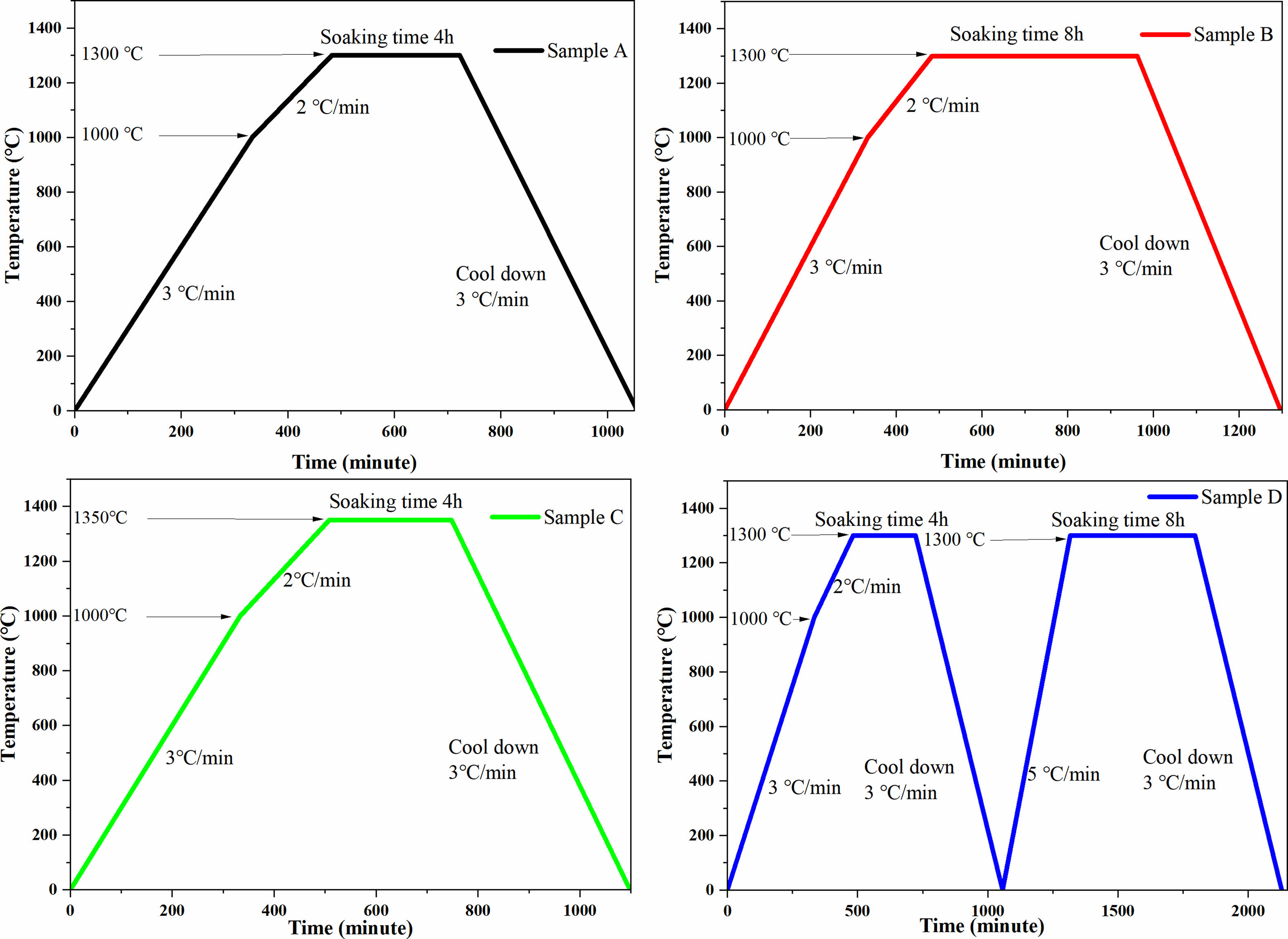
BaTiO3 and SrTiO3 powders were stoichiometrically weighed and mixed for 12 h using ethanol and ZrO balls after drying. The mixtures were prefired at 1250 °C for 4 h and then sieved using a 300-mesh screen. After that, Al2(SO4)2·18H2O, ZnSO4·7H2O, H2NCONH2, and C12H25O3S·Na were dissolved in distilled water, and then BST was added to the solution according to the ZA/BST molar ratio of 2:8 with ultrasonic treatment for 15 min. Subsequently, the dispersed solution was poured into a hydrothermal kettle, which was placed in a vacuum drying oven at 160 ℃ and reacted for 8 hours. After that, the hydrothermal powders were filtered, centrifuged, ground, and calcined at 1100 °C for 4 hours. After sieving, the polyvinyl butyral binder was added to the powders for granulation and then pressed into cylindrical green bodies. Next, heat treatment (550 °C) was applied to the green bodies for 4 h to burn the binders off. As shown in Fig. 1, some of the debindered samples were sintered at 1300 ℃ for 4 hours (Sample A) and 8 hours (Sample B) and at 1350 ℃ for 4 hours (Sample C) for continuous grain growth. To successfully carry out double sintering, we sintered ZA/BST at 1300 ℃ and 1350 ℃, among which the sample sintered at 1350 ℃ showed intergranular fracture. Therefore, 1300 ℃ was selected as the first sintering temperature. Therefore, the remaining samples were first sintered at 1300 ℃ for 4 hours and further resintered at 1300 ℃ for 8 hours (Sample D) for the double sintering group.
X-ray diffraction (XRD, Bruker AXS D8 Advance, Germany) was used to analyse the phase composition of the ceramics. The microstructure and element distribution of the sample were tested by scanning electron microscopy (SEM, Quanta 250 USA) and energy dispersive spectrometry (EDS). An impedance analyser (Tonghui 2827C, China) was used to measure the dielectric properties of the ceramics. The leakage current of ceramic samples was tested by a ferroelectric analyser (Radiant, YQ094244 USA). The sample density and hole fraction were measured using the Archimedes drainage method.
|
Fig. 1 Different sintering systems: Sample A (sintering at 1300 °C for 4 h), Sample B (sintering at 1300 °C for 8 h), Sample C (sintering at 1350 °C for 4 h), and Sample D (sintering at 1300 °C for 4 h and then sintering at 1300 °C for 8 h). |
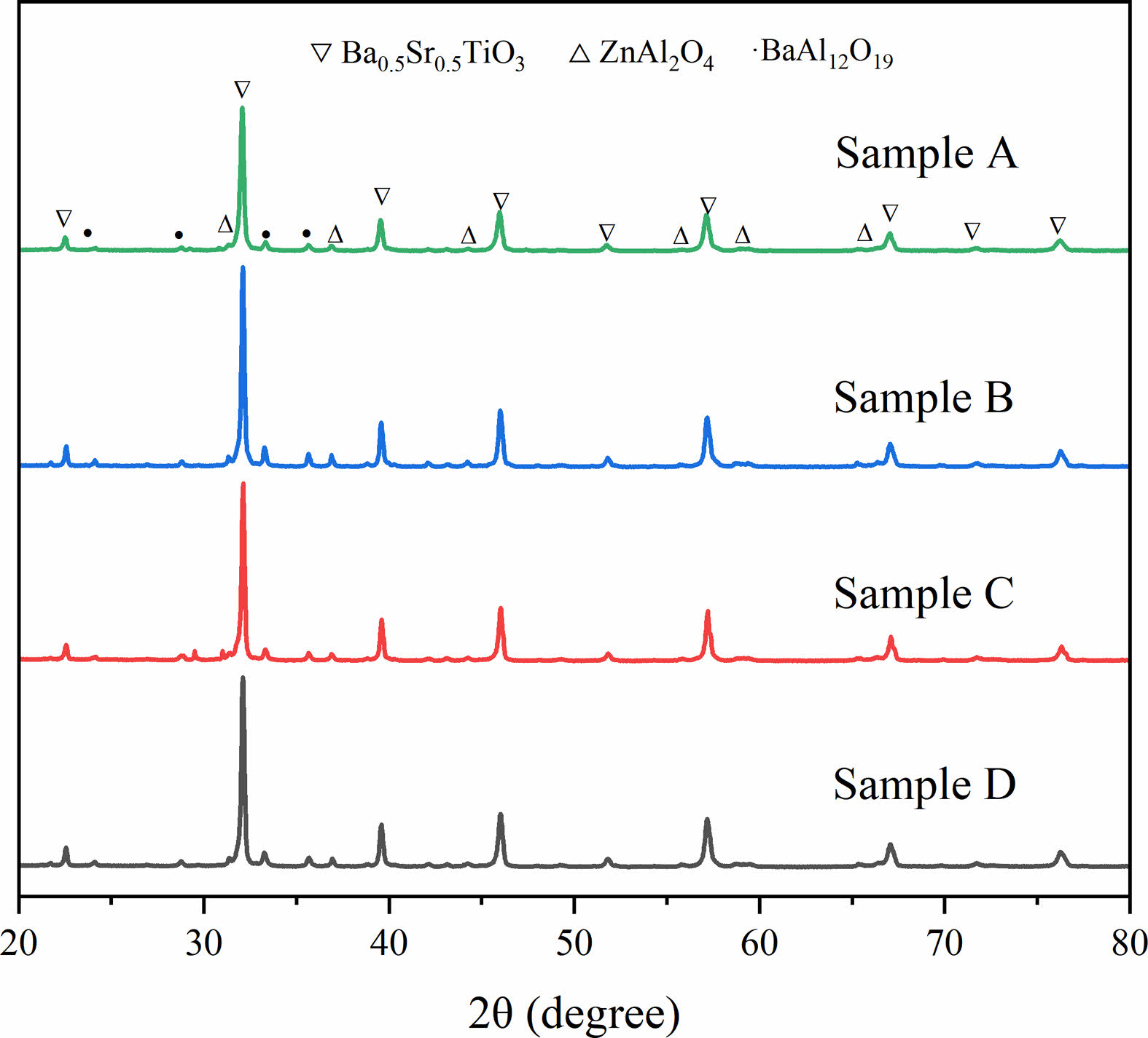
Figure 2 shows the XRD patterns of the prepared BST/ZA. A new third phase BaAl12O19 was formed in addition to spinel-structured ZnAl2O4 (PDF#01-1146) and perovskite-structured Ba0.5Sr0.5TiO3 (PDF#39-1395) due to ion diffusion between ZA and BST. The formation of the third phase was related to the instability of the BST structure caused by the eccentric displacement of Sr2+ ions [21]. Instability of the BST structure led to Al3+ entering the BST lattice, which caused BST lattice distortion.
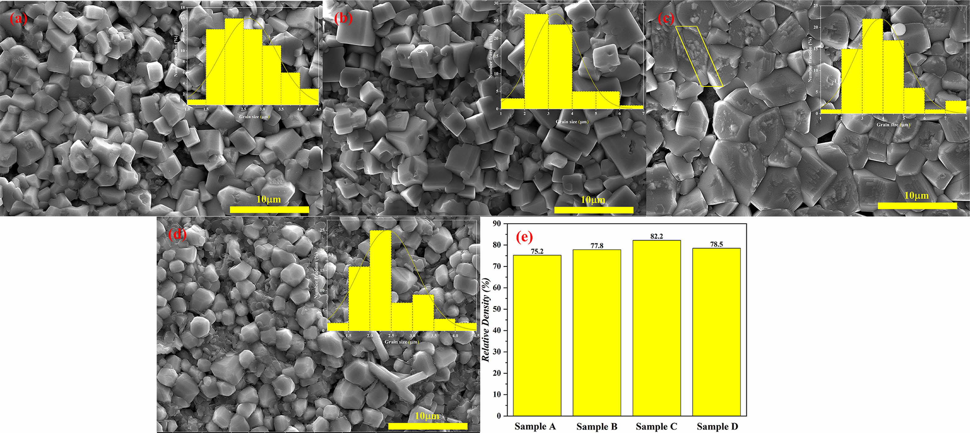
From the SEM image (Fig. 3), it was found that all samples showed different pore sizes. With the increase in sintering temperature and the extension of holding time, ZA/BST composite ceramic grains showed different degrees of growth. Fig. 3(a-c) exhibits distinct cubes, while Fig. 3(d) is more rounded and smoother. Comparing Sample D with Sample A, it can be found that the grain growth in Sample D is inhibited due to the inadequate energy. Sample A and Sample B has a porosity greater than 1 mm, which is very detrimental to ferroelectric performance [22]. Sample C has a shallow crack (upper left corner shown in Fig. 3(c)), which may be an intergranular fracture caused by impurity ions. Increasing sintering temperature and prolonging sintering time are beneficial to increase relative density. The relative density of the Sample D is about 3% higher than that of the Sample A. Figure 3(d) shows that we have not obtained Sample D is obtained by repeated sintering of Sample A. The large number of small flake grains is attached near the grains of Sample D, which may be due to the migration of ZA attached to BST to the grain gap of BST during the secondary sintering process, resulting in a relative increase.
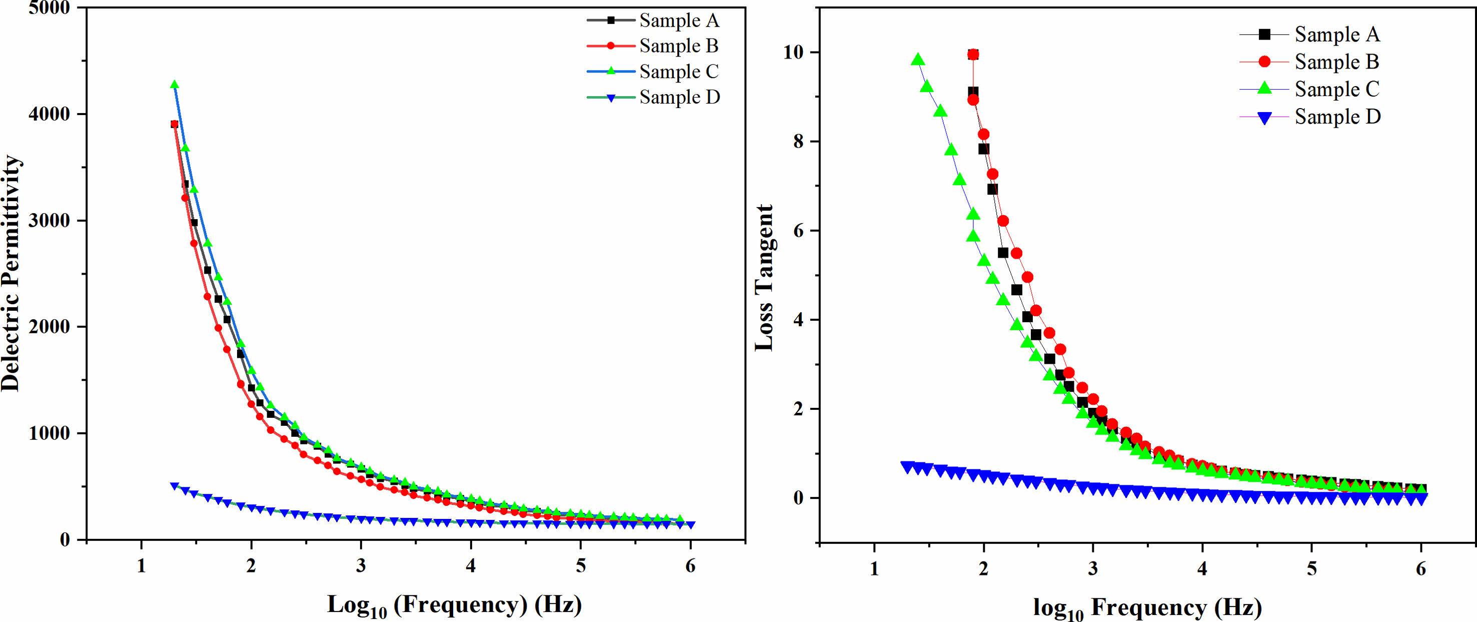
Figure 4 shows the variation in dielectric permittivity and loss of BST/ZA composite ceramics in the frequency range of 20 Hz-1 MHz at room temperature. The dielectric permittivity and loss decrease with increasing frequency, which is attributed to the polarization behavior of dielectric materials [23]. The influencing factors in the low frequency range are mainly due to space charge polarization and orientation polarization, and the influencing factors in the high frequency range are mainly due to relaxation polarization and displacement polarization. The dielectric permittivity and dielectric loss of the double sintered samples are much lower than those of the other samples. We believe that this low dielectric constant and loss may be due to the change in morphology after double sintering, as we discussed in Fig. 3. Generally, the dielectric permittivity of pure BST is approximately 7500, and the dielectric constant of ZA added to BST is approximately 6000-200, while the dielectric constant of 0.8 BST/0.2ZA with the double sintering process is approximately 30% of that of the traditional sintering method, and the loss is approximately 10%.
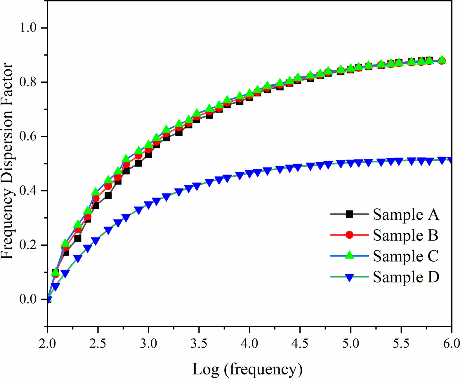
To obtain the stability of the dielectric permittivity on composite ceramics with different frequencies, the frequency dispersion factor is adopted:

where F(x) represents the frequency dispersion factor at x Hz, er(100) is the permittivity at 100 Hz, and εr(x) represents the permittivity at x Hz. A low F(x) represents better dielectric frequency stability [24]. The calculated results of F(x) of the composite ceramics of the single sintering samples and the double sintering sample are shown in Fig. 5. The frequency dispersion factor shows an upwards tendency with increasing frequency. The frequency dispersion factor rises rapidly below 1000 Hz, and the frequency dispersion factor rises slowly above 1000 Hz. This is because the dielectric permittivity changes rapidly at low frequencies, and the lower dielectric permittivity does not change significantly at high frequencies. At 1 MHz, the maximum frequency dispersion factors corresponding to samples A, B, C, and D are 0.88, 0.87, 0.87, and 0.51, respectively. This indicates that the Sample D has better frequency stability than the single sintering samples.
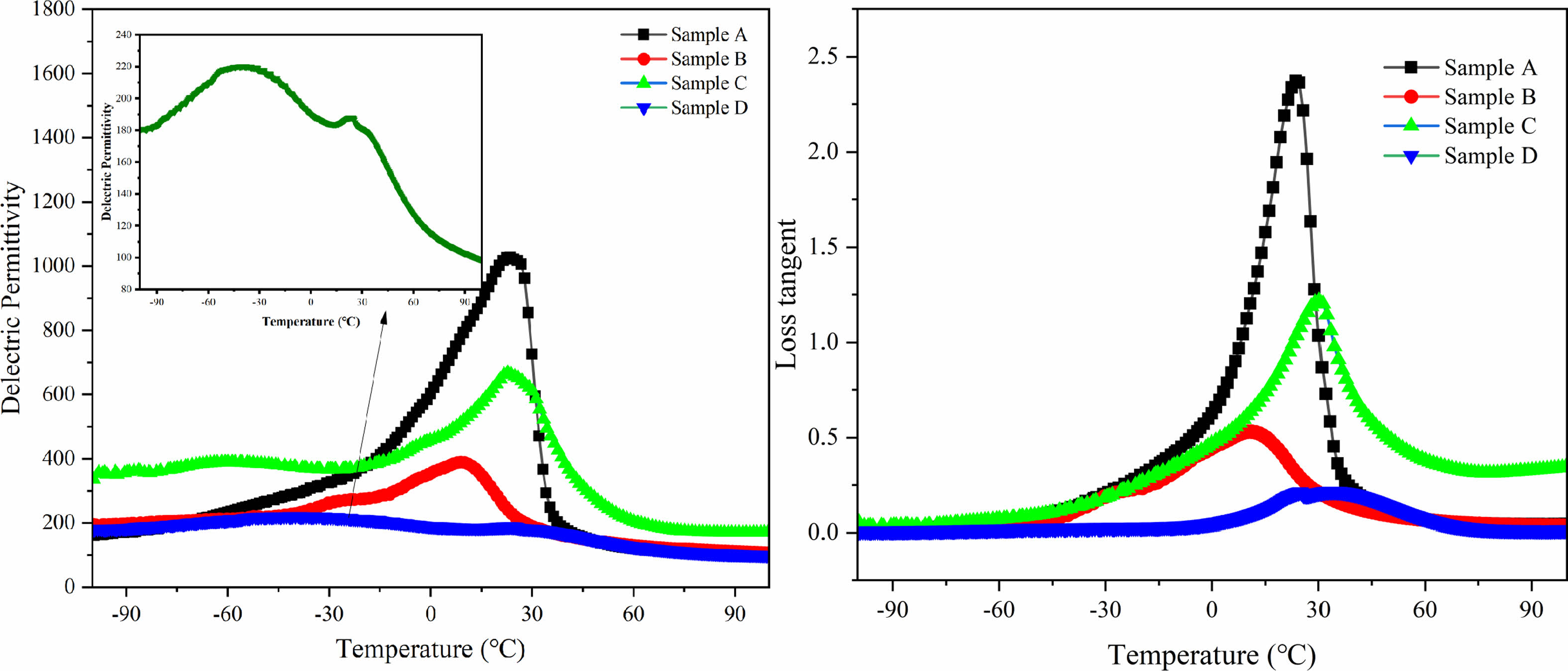
To illustrate the dielectric properties of BST/ZA composite ceramics, the temperature-dependent permittivity was measured from -100 ℃ to 100 ℃ at 10 kHz. The results are shown in Fig. 6. Among all samples, only Sample D has the lowest dielectric permittivity of 220 at 10 kHz, which is related to the weakening of space charge polarization by secondary sintering. Since a large amount of Al3+ enters the BST lattice to form a third phase (BaAl12O19) [25], the dielectric peaks of Sample A, Sample B, and Sample C are all above 0 °C.
Compared with the single sintering samples, the dielectric peak of the double sintering sample moved to low temperature. The dielectric loss was greatly reduced due to the dense structure. The dielectric peak of the double sintering sample was approximately -41 ℃, indicating that the transformation of the ferroelectric phase to the paraelectric phase was completed around this temperature. The main reason for the low phase transition temperature of Sample D is that Sample D has smaller grains and interface polarization guided by defects at grain boundaries. It is known from SEM that Sample D has more grain boundaries than Sample B and Sample C. It is well known that there are higher energy and more defects at the grain boundary [26, 27], resulting in structural instability in the grain boundary region. The decrease of the phase transition temperature of Sample D is due to the instability of the crystal structure caused by the second sintering to increase the energy of the grain boundary.
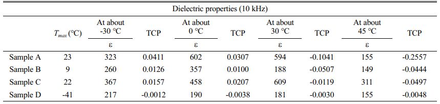
Table 1 lists the TCP values calculated (temperature: -30 ℃, 0 ℃, 30 ℃, 45 ℃). Increasing the sintering temperature and extending holding time, the TCP value will decrease.The lower the TCP value, the better the temperature stability. The TCP value of the Sample D at all temperatures is closest to 0. TCP is related to the dielectric peak broadening effect. The lowest TCP value of Sample D may be caused by high surface energy at grain boundaries and improvement of density. In summary, the thermal stability of Sample D is maintained at a good level over a wide temperature range. Enhance in dielectric temperature stability is consistent with the broadening of the dielectric peak. This is very beneficial to the application of microwave dielectric ceramics at different temperatures [28].
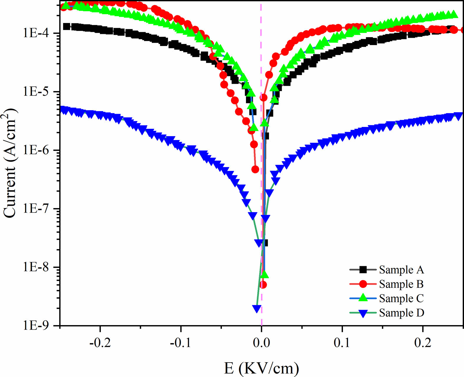
To illustrate the influence of two group composite ceramics on the conductivity behavior of BST/ZA ceramics, the functional relationship between the current density and the electric field (J-E curve) was tested, as shown in Fig. 7. J-E curves of all samples showed the asymmetry phenomenon of the axis indicating that there was a bias electric field in the ceramic, which may be caused by the imbalance between oxygen vacancies and charged carriers [29]. The current density of Sample D at the maximum electric field intensity of 0.25 kV/cm is 3.98 × 10⁻⁶ A/cm2, which is significantly lower than that of other samples. The improved electrical insulation may be related to the increase of grain boundary and the increase of relative density caused by secondary sintering. The low loss of the Sample D in Fig. 4(b) and Fig. 6(b) may also contribute to the low leakage current.
|
Fig. 2 XRD of BST/ZA composite ceramics |
|
Fig. 3 SEM images of BST/ZA composite ceramics at (a) Sample A, (b) Sample B, (c) Sample C and (d) Sample D. (e) is the relative density of all ceramics. The inset shows the grain size distribution. |
|
Fig. 4 Frequency-dependent relative permittivity (ε) of BST/ZA composite ceramics. |
|
Fig. 5 Frequency dispersion factor with frequency for BST/ZA composite ceramics. |
|
Fig. 6 Temperature dependence of permittivity and loss tanδ of BST/ZA composite ceramics measured at 10 kHz. The inset shows the temperature dependence of the permittivity of Sample D. |
|
Fig. 7 The J-E curves of BST/ZA composite ceramics under different sintering systems. |
In summary, BST/ZA composite ceramics were synthesized by the solid-phase method and hydrothermal method. Different sintering methods significantly changed the crystal structure and performance of BST/ZA composite ceramics. Compared with the single sintering samples, the crystal grains of the samples prepared by double sintering were more uniform and had better frequency stability. The permittivity and loss of single sintering samples were significantly reduced, the dielectric peak shifted to the low temperature direction, and the dielectric temperature stability of the sample was effectively improved with TCP = -0.0086, which was 10 times smaller than that of pure BST. The composite ceramics of the double sintering sample in this study have suitable permittivity, low loss, and good dielectric temperature stability for practical applications.
This research was supported by the Shandong Province Natural Science Foundation (ZR2020ME032).
- 1. W. Jin, J. Tan, J. Yan, Y. Tao, N. Yao, X. Ruan, and C. Pei, J. Ceram. Process. Res. 22[6] (2021) 675-678.
-

- 2. S.-O. Yoon, S. Kim, Y.-H. Kim, S.-J. Kim, and S.-M. Jeong, J. Ceram. Process. Res. 17[10] (2016) 1024-1027.
-
- 3. E. Jeon, H. Kim, and J. Yun, J. Ceram. Process. Res. 13[3] (2012) 239-242.
-
- 4. R.-H. Liang, X.-L. Dong, Y. Chen, F. Cao, and Y.-L. Wang, Mater. Res. Bull. 41[7] (2006) 1295-302.
-
- 5. L.-B. Kong, S. Li, T.-S. Zhang, J.-W. Zhai, F-Y-C. Boey, and J. Ma, Prog. Mater. Sci. 55[8] (2010) 840-893.
-
- 6. K.-C. Sekhar, S.-H. Key, K.-P. Hong, C.-S. Han, J.-M. Yook, D.-S. Kim, J.-C. Kim, J.-C. Park, and Y.-S. Cho, Curr. Appl. Phys. 12[3] (2012) 654-658.
-
- 7. H. Dong, D. Jin, C. Xie, J. Cheng, L. Zhou, and J. Chen, Mater. Lett. 135 (2014) 83-86.
-
- 8. X.-F. Zhang, Q. Xu, D. Zhan, B.-H. Kim, K. Zhao, and D.-P. Huang, J. Ceram. Process. Res. 14[3] (2013) 430-435.
-
- 9. J. Zhang, B. Shen, J. Zhai, and X. Yao, Ceram. Int. 39[5] (2013) 5943-5948.
-
- 10. R. Liang, Z. Zhou, X. Dong, G. Wang, F. Cao, Z. Hu, and K. Jiang, Ceram. Int. 41[1] (2015) S551-S556.
-
- 11. W. Wang, M. Zhang, L. Xin, S. Shen, and J. Zhai, J. Alloys Compd. 809 (2019) 151712.
-
- 12. Y.-S. Park and E.-S. Kim, J. Ceram. Process. Res. 23[6] (2022) 920-926.
-
- 13. L. Cui, R. Niu, and W. Wang, J. Ceram. Process. Res. 23[1] (2022) 57-61.
-
- 14. D.-A. Tuan, L.-D. Vuong, V.-T. Tung, N.-N. Tuan, and N.-T. Duong, J. Ceram. Process. Res. 19[1] (2018) 32-36.
-
- 15. G.-G. Yao, J. Ceram. Process. Res. 16[1] (2015) 41-44.
-
- 16. A. Ozdogan and H. Ozdemir, J. Prosthet. Dent. 125[3] (2021) 527.e1-527.e7.
-
- 17. M.-S. Kim, S.-C. Lee, S.-W. Kim, J. Jo, S.-J. Jeong, I.-S. Kim, and J. Song, J. Ceram. Process. Res. 14[2] (2013) 260-264.
-
- 18. X.-W. Ren, L. Zeng, Z.-M. Wei, X.-Z. Xin, and B. Wei, J. Prosthet. Dent. 115[1] (2016) 109-114.
-
- 19. H.-I. Meng, H. Xie, L. Yang, B. Chen, Y. Chen, H. Zhang, and C. Chen, J. Mech. Behav. Biomed. Mater. 88 (2018) 362-369.
-
- 20. Y. Fang, A. Hu, S. Ouyang, and J.-J. Oh, J. Eur. Ceram. Soc. 21[5] (2001) 2745-2750.
-
- 21. Y.-X. Wang, Solid. State. Commun. 135[5] (2005) 290-293.
-
- 22. Y. Bi, J. Tao, Y. Wu, L. Li, Y. Xu, E. Hu, B. Wu, J. Hu, C. Wang, and J. Xiao, Science 370[6522] (2020) 1313-1317.
-
- 23. Y.-Z. Xue, R.-C. Xu, Z.-H. Wang, R.-L. Gao, C.-Y. Li, G. Chen, X.-L. Deng, W. Cai, and C.-L. Fu, J. Electron. Mater. 48 (2019) 4806-4817.
-
- 24. S. Liu, Y. Guo, J. Li, S. Wu, J. Xu, E. Pawlikowska, J. Kong, A.-M. Rydosz, M. Szafran, and F. Gao, Compos. Sci. Technol. 219 (2022) 109228.
-
- 25. C. Li, H. Xiang, J. Chen, and L. Fang, Ceram. Int. 42[9] (2016) 11453-11458.
-
- 26. Y.-G. Wang, W.-L. Zhong, and P.-L. Zhang, Solid. State. Commun. 92[6] (1994) 519-523.
-
- 27. B.-W. Lee and K.-H. Auha, J. Ceram. Process. Res. 2[3] (2001) 134-138.
- 28. T. Teranishi, R. Kanemoto, H. Hayashi, and A. Kishimoto, J. Am. Ceram. Soc. 100[3] (2016) 1037-1043.
-
- 29. C. Zhou, W. Cai, Q. Zhang, H. Wu, H. Wu, R. Gao, G. Chen, Z. Wang, X. Deng, and C. Fu, Mater. Chem. Phys. 258 (2021) 124001.
-
 This Article
-
2023; 24(2): 336-341
Published on Apr 30, 2023
- 10.36410/jcpr.2023.24.2.336
- Received on Nov 14, 2022
- Revised on Jan 6, 2023
- Accepted on Jan 27, 2023
Services
- Abstract
introduction
experimental procedure
results and discussion
conclusions
- Acknowledgements
- References
- Full Text PDF
Shared
Correspondence to
- Mingwei Zhang
-
School of Materials Science and Engineering, Shandong University of Technology, Zibo 255049, Shandong, People’s Republic of China
Tel : +86-533-2781317 Fax: +86-533-2781317 - E-mail: zhang6666666@163.com
Clean-Energy Research Institute(CRI), Hanyang University, 222, Wangsimni-ro, Seongdong-gu, Seoul, 04763, Korea
E-mail: jcpr@hanyang.ac.kr