


- Preparation and performance of fly ash-loess based ceramic membrane supports: Effect of calcium carbonate addition and sintering temperature
Zhi Tonga,*, Miaoyu Lia, Dachuan Lib, Kui Wub and Xiaoyu Yanga
aSchool of Environmental and Chemical Engineering, Xi’an Polytechnic University, Xi’an 710000, China
bShaanxi Modern Architectural Design and Research Institute, Shaanxi Xi'an 710000, ChinaThis article is an open access article distributed under the terms of the Creative Commons Attribution Non-Commercial License (http://creativecommons.org/licenses/by-nc/4.0) which permits unrestricted non-commercial use, distribution, and reproduction in any medium, provided the original work is properly cited.
Porous mullite ceramic membrane supports were prepared by fly ash as the main raw material, with addition of loess and bauxite in the ratio of silicon to aluminium in the mullite phase (3Al2O3-2SiO2), calcium carbonate as pore-forming agents and polyvinyl alcohol as the binder. The effects of calcium carbonate addition (0, 5, 10, and 15 wt%) and sintering temperature on the performance of prepared supports, including crystalline phase evolution, microstructure, porosity, flexural strength, and pure water flux, were investigated. The results shows that the increase in sintering temperature is beneficial to the formation of the mullite crystalline phase and improves flexural strength. When the sintering temperature reached 1200 °C and the calcium carbonate content was 5%, the porosity of the support was 46.3% and the flexural strength was 77.7 MPa. Based on the experiments, central composite experiments and response surface analysis were carried out to optimise the preparation conditions, and determine the optimum amount of calcium carbonate addition and sintering temperature. The results of the study are of reference value for the study of inorganic ceramic membrane support
Keywords: Ceramic membranes support, Fly ash, Porous mullite, Sintering temperature, Calcium carbonate
Compared to traditional polymer membranes, ceramic membranes have the advantages of excellent chemical stability, high mechanical strength and high separation efficiency [1-4]. Currently, ceramic membranes are widely used in industries such as wastewater treatment [5], flue gas separation [6], and juice separation [7]. Ceramic membranes usually consist of a support layer, a transition layer, and a separation layer. Although the separation layer determines the filtration accuracy of the ceramic membrane. However, the filtration characteristics of ceramic membranes depend primarily on the support layer. The support layer not only provides the ceramic membrane with flexural strength and pore structure but also has excellent acid and alkali resistance and a long service life [8]. Currently, ceramic membrane supports are mainly prepared from mixtures of oxides such as alumina and zirconia, which have been widely noted for their excellent physicochemical properties. However, the lattice of the oxide needs to be transformed at high temperatures, which increases the difficulty of sintering. In addition, the high price of raw materials leads to high costs for the preparation of the support [9, 10].
Nowadays, scholars have focused their researches on the resourceful use of industrial waste [11]. Industrial solid waste is generally classified into metallurgical slag, red mud, fly ash, chemical gypsum and others [12]. Fly ash, as a by-product of coal combustion in thermal power plants and un-weathered fly ash, is a serious source of environmental pollution. Due to the presence of heavy metals, fly ash can contaminate soil and water sources and has alkaline oxides and salts that can lead to salinisation of the land and pollution of the environment [13, 14]. Even so, fly ash is still widely used in industry due to its main components of SiO2 and Al2O3. Fly ash is commonly used as a construction material for building walls and roads, but is poorly utilised. In contrast, the use of fly ash for the preparation of catalysts and zeolites and ceramic membrane supports is more valuable for resource utilisation. The preparation of ceramic membrane supports from fly ash, in addition to the main components meet the preparation requirements of the support, the alkaline oxides that cause pollution to the environment have a steady seat that promotes sintering. Not only solves the problem of the preparation cost of the support, but also realises the resourceful use of solid waste.
Li [15] used fly ash and loess as the main raw materials and carboxymethyl cellulose as the pore-forming agent to prepare ceramic membrane supports. It was demonstrated that the best performance was achieved when the sintering temperature was 1100 °C and the holding time was 2.5 h. The pure water flux was 2846.9 L/m2·h·MPa, the flexural strength was 17.2 MPa and the linear shrinkage was 4.5%. Shen [16] prepared ceramic membrane support from fly ash and loess with a pure water flux of 5365 L/m2·h·MPa and a porosity of 32.1% when the sintering temperature was 1110 °C. Tong [17] used fly ash, loess to prepare a ceramic membrane support. When the sintering temperature was 1130 °C, the porosity was 26.43%, the flexural strength was 27.33 MPa and the water flux was 3165.13 L/(m2·h·MPa). However, due to the high content of SiO2 in fly ash, the main crystalline phase is quartz phase. Compared to mullite phase ceramic membrane supports, ceramic membrane supports prepared from fly ash as the main raw material generally have lower flexural strength, porosity and internal structural stability to be improved, and are less resistant to acids and bases.
In this study, accordingly, the mullite ceramic membrane support was prepared by fly ash with loess and bauxite as raw materials, calcium carbonate as a pore-forming agent, and polyvinyl alcohol as a binder. (1) Investigating the effect of calcium carbonate content and sintering temperature on the properties of the support (2) Using response surface curve analysis to optimize preparation solutions, determine the optimum values for calcium carbonate content and sintering temperature. Firstly, the chemical composition of the raw material and the internal crystalline phases were analyzed by XRF and XRD. Secondly, the internal crystalline phase of the support is analyzed by XRD and the microstructure is characterized by scanning electron microscopy. The porosity, flexural strength, and pure water flux of the support are tested. Finally, the experimental conditions were optimized by a central composite experiment to explore the best experimental protocol. This study dedicates to preparing and studying the fly ash-loess based ceramic membrane supports and provides a guidance for ceramic membrane supports.
Material
In this study, ceramic membrane supports were prepared by adding loess (200 mesh sieve, shaanxi, China) and bauxite (calcined) (200 mesh sieve, shaanxi, China) to fly ash (200 mesh sieve, shaanxi, China) as the main raw materials, calcium carbonate (CaCO3, Baishi Chemicl Co. Ltd, TianJin, China) as a porogenic agent and polyvinyl alcohol (PVA, Sinopharm Group Chemical Reagent Co. Ltd, China) as binder.
Support preparation
The porous mullite ceramic membrane support was prepared by adding loess and bauxite to fly ash as the main raw materials, (the amount of loess and bauxite added was determined according to the ratio of silicon to aluminium in the mullite phase (3Al2O3-2SiO2)). Among them, loess has certain binder effect and the pore structure is formed by the phenomenon of burning loss in the sintering process, while bauxite can adjust the content of aluminum element in the raw material. With calcium carbonate (CaCO3) as the pore-form agent and polyvinyl alcohol (PVA) as the binder.
In this experiment, the raw materials were first pretreated. The loess, bauxite and fly ash were ball milled in a ball mill (KYM-D, 0.5KG High aluminum ball mill can, Steel ball) at a constant speed of 500 rpm for 9 hours. Using dry ball milling, Ball material ratio 4:1, the quality of the ball mill steel ball is 200 g, the quality of the material is 50 g. The loess, fly ash and bauxite were then passed through a 200 mesh sieve (Standard Sieve Factory, China). The purpose of the pretreatment was divided into two points: firstly, to remove impurities contained in the raw material to avoid affecting the experimental results. The second is to reduce the size of the raw material particles so that the particle size distribution is more compact and helps to increase the density of the support.
The pretreated raw materials were mixed proportionally and added to a mixture containing 0 wt%, 5 wt%, 10 wt% and 15 wt% CaCO3, referred to as C0, C5, C10 and C15. After the addition of PVA (5 wt%), deionised water was added and placed in a beaker and stirred for 2 hours with a mechanical stirrer (Guohua Electric, JJ-1). The beaker was placed in a 90 °C water bath (De'ao Instrument Manufacturing, HH-6) and the water content of the mixture was adjusted to 10~15% to make it malleable. The mixture was aged in a constant temperature and humidity incubator (Jinghong Experi- mental Equipment, DGH-9247A) for 12 hours under seal and then placed in an extruder (homemade in the laboratory) at a pressure of 10 MPa to extrude wet billet tubes of 8 mm diameter, 3 mm thickness and 10 cm length. The wet blanks were dried in a constant temperature and humidity incubator at 50 °C for 2 hours and then placed in a muffle furnace for sintering (YinganMeiCheng Scientific Instruments, SR1X-4-13). The prepared support were sintered at room temperature ~1300 °C and at temperature rise rate of 3 °C/min. After sintering was completed, the supports were characterized.
Characterization Method
The chemical composition of the raw material is analysed using quantitative analysis by X-ray fluorescence spectroscopy (panalytical axios) (Sample preparation: Powder pressing method). The transformation or dis- appearance of the raw material composition during the sintering process is analysed using thermogravimetric analysis (Mettler-Toledo, Switzerland (TG/DTA 851)) to determine the optimum sintering conditions. (Temperature range: 30~1300 °C, heating rate: 10 °C/min, atmosphere: air, gas flow: 100 ml/min, crucible type thermal analysis alumina crucible, size 9×9.25 mm) The crystalline phases of the raw material and the support were analysed by X-ray diffraction (Rugaku, Japan (BD68000156-1)). (start angle = 5, end angle = 90, step width = 0.02, wavelength = 1.54056, Co target, incident radiation 36 kV, 20 mA) The microstructure and pore size distribution of the supports were observed using scanning electron microscopy (Carl Zeiss Germany (JCM-6000) (Voltage.: 15.0 KV, Sample preparation: Samples were previously coated with gold using a sputtering equipment (SuPro instruments ISC150) under vacuum for 120 s at 50 mA). The pore size and porosity of the support body were tested by mercury injection meter (Mike Instruments of America, AutoPore IV9500).
The porosity of the support is obtained by analysis of the porosity calculation formula [18]

Where (M1/g) is the weight of the dry support body, which is completely submerged in water, and (M2/g) and (M3/g) are the mass of the saturated support body in the air and the mass in water respectively.
The flexural strength of the support was tested using the "Test Method for Bending Strength of Ceramic Pipes" GB/T 2833-1996 [19]. The distance between the two lower support cutters was adjusted to 80 mm using a universal material testing machine (Shenzhen Xinsanshi Material Testing Co., Ltd. CMT5105) and the cutter was lowered at a constant rate of 0.5 mm/min close to the support body so that a uniform load was gradually applied to the support and the load value P shown on the computer when the support broke was recorded.

where σb is flexural strength, P is sample load at fracture, L is the distance between the two lower cutters, d is the internal diameter of the sample at fracture, S is sample wall thickness at fracture.
The pure water flux is measured by Laboratory homemade equipment in the laboratory. The pure water flux of the support is calculated according to the formula.

whereJ (L/m2·h·MPa) is the pure water flux L/m2·h·MPa; V is the sampling volume (L) at 0.1 MPa, respectively; A(m2) is the effective permeation area of the sample; t(h) is the permeation time.
Analysis of raw materials
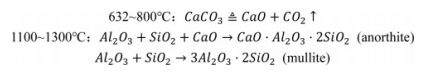
In order to further investigate the properties of the support, the main raw materials required for their preparation were analysed. Table 1 lists the main chemical compositions of the raw materials used in the preparation of the support. Fig. 1 shows the X-ray diffraction pattern of the raw materials, which visualises the composition of the crystalline phases within each raw material.
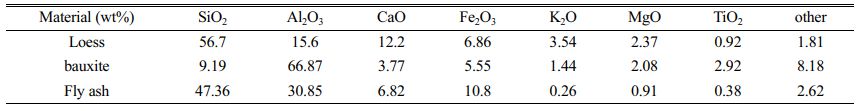
Table 2 lists the chemical compositions of fly ash, loess and bauxite characterized by XRF analysis. From Table 2, we can see that the main components of fly ash and loess are SiO2, followed by Al2O3. Among them, fly ash is a grey barren raw material, adding loess can not only increase the viscosity between the raw material particles, but also creates a stable pore structure by generating sintering phenomena during the sintering process. In addition, fly ash and loess contain Fe2O3, TiO2 and other low melting point substances, which will cause defects in the crystal structure and activate the lattice. The main chemical composition of bauxite is Al2O3, which is used in the experiments as a source of aluminium to regulate the ratio of silicon to aluminium in the raw material. We can note that the raw materials all contain some alkali metal oxides, which have the effect of promoting sintering.
Fig. 1 shows the XRD plots of loess, bauxite and fly ash. The results show that the main crystalline phase in the fly ash is the quartz (SiO2, PDF-#4850798) phase, followed by the mullite (Al6Si2O13, PDF#-150776) phase. The main reason for this phenomenon is the high SiO2 content in the fly ash. The main crystalline phase of the loess is quartz (SiO2, PDF-#850798), anorthite (CaAl2Si2O8, PDF-#411468) and a small amount of calcite (CaCO3, PDF-#050586). The peak observed between 20° and 30° (2θ) is attributed to the presence of an amorphous silicate glass phase. The main crystalline phase in bauxite is the mullite (Al6Si2O13, PDF#-150776) phase, followed by corundum (Al2O3, PDF#-461212), Cristobalite (SiO2 PDF#82-0512) and Diaspore (AlO(OH), PDF-#050355). In general, the mullite phase in bauxite is formed by the calcination of minerals contain alumin and silicon at high temperatures. It has also been shown that the main phases in bauxite are hard aluminium monohydrate (AlO(OH)), kaolinite (Al2O3·2SiO2·2H2O) and quartz (SiO2), which can form mullite and corundum after sintering [20].
Sintering behavior of supports
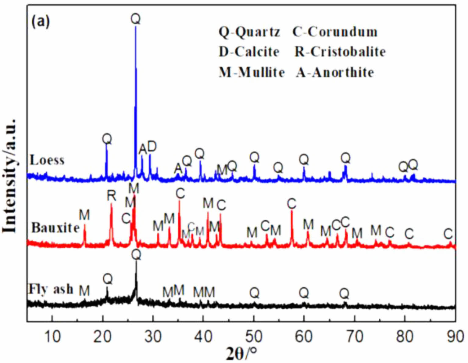
Fig. 2 shows the TG-DTG-DTA curves for the C0 and C15 samples. In this experiment, C0 and C15 supports were selected for analysis with the aim of determining the changes in the mass and thermal effects of the raw materials and additives (poro-form agents, binders) within the supports during the increase in temperature, and the range of changes in the weight of the raw materials and additives at different temperatures. The sintering process and the properties of the proppant are investigated and analysed according to the range of variation of each indicator analysed for the C0 and C15 proppants. As can be seen from the Fig 2(a), the support undergoes two distinct weight loss processes during sintering. For the C0 sample, a weight loss of 0.9% was observed from 241 °C to 336 °C, corresponding to a heat absorption peak at 271 °C, which was caused by the decomposition of PVA [21]. The weight loss in the second stage of the support occurs in the range of 632 to 738 °C with a mass loss of 0.94% and a heat absorption peak at 694 °C, which is caused by the decomposition of calcite (CaCO3) in the loess [17].
For C15, the first stage of weight loss occurs between 241 °C and 336 °C where a 0.7% weight loss occurs. The cause is the same as for C0, caused by the decomposition of PVA. However, the weight loss process in the second stage shows a broadening of the weight loss range (632 °C~795 °C) and an increase in the weight loss rate to 3.3%, with an obvious heat absorption peak at 753 °C. This indicates that the different weight loss rates are caused by different levels of CaCO3: (1) the decomposition of calcite in the raw loess; (2) the decomposition of the additive CaCO3. As the temperature continues to increase from 800 °C to 1300 °C, the C0 and C15 supports no longer experience significant weight loss, but form significant exothermic peaks at 1256 °C and 1160 °C respectively, indicating that new crystalline phases are formed in the supports between 1000 and 1300 °C. In conjunction with XRD analysis, the C0 support produces a mullite crystalline phase at 1257 °C and the appearance of an exothermic peak at 1160 °C in the C15 support is attributed to the formation of calcium feldspar within the support.
In a previous report, approximately 13.44% mass loss of even occurred in the sample fabricated by using coal fly ash as starting materials and CaCO3 as additives [22]. In the present work, a single addition of CaCO3 was also effective in maintaining the highly porous structure of support sintered at higher temperatures (632-795 °C).
Phase evolution of supports
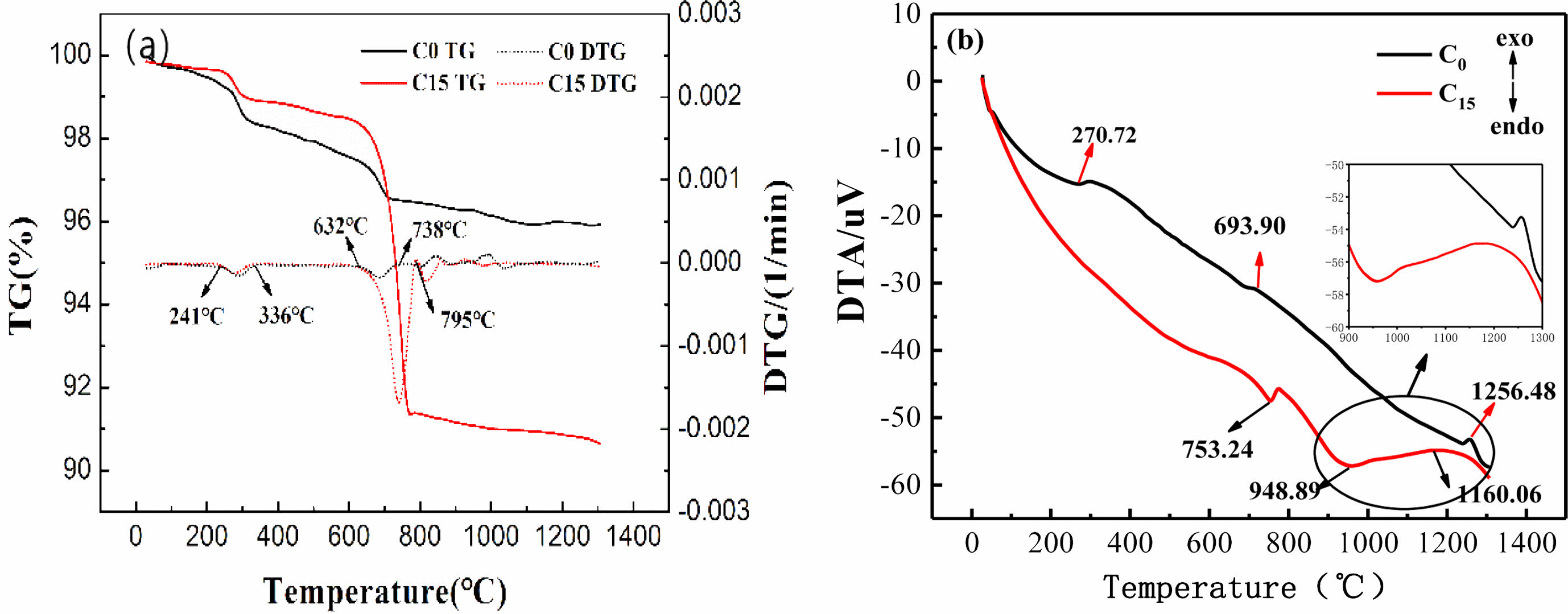
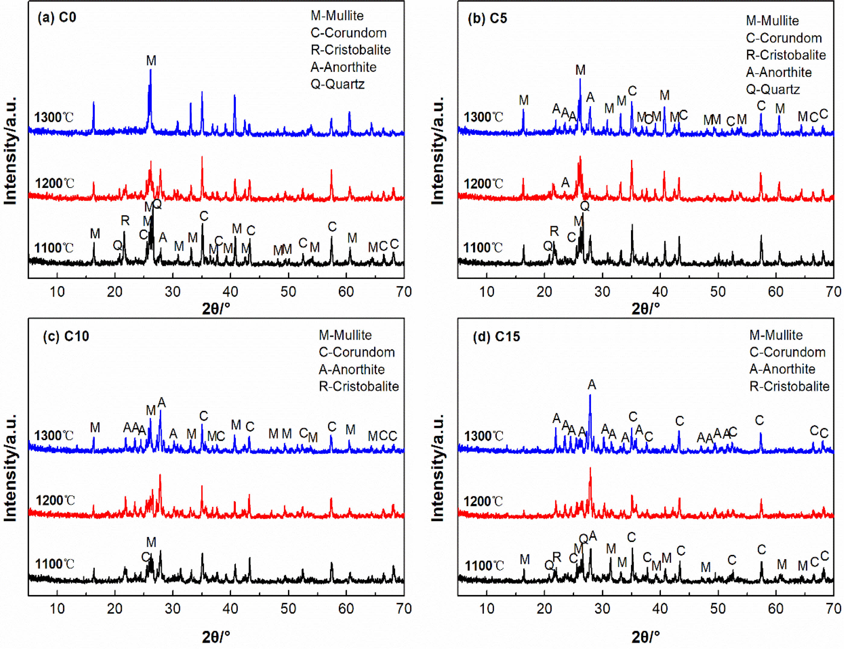
Fig. 3 shows XRD plots of the ceramic membrane supports with different CaCO3 contents after sintering at 1100 °C to 1300 °C for 2 h.
Fig. 3(a) shows that, The main crystalline phases of C0 support sintered at 1100 ℃ are mullite (3Al2O3·2SiO2, PDF#79-1453), corundum (Al2O3, PDF#74-1081), cristalite (SiO2, PDF#82-0512), quartz (SiO2, PDF#82-0512). PDF#79-1906) and anorthite (CaO·Al2O3·2SiO2, PDF#41-1486). Compared with the XRD of raw materials (Fig. 1), the crystal phase of C0 support is similar to that of raw materials, but does not contain calcite phase, because calcite in loess is decomposed at 600~800 ℃. When the temperature increased from 1100 ℃ to 1300 ℃, the diffraction peak intensity of quartz, cristobalite and corundum gradually weakened, while the diffraction peak intensity of mullite first decreased at 1200 ℃ and then increased at 1300 ℃. Anorthite exists in all temperature ranges, and its diffraction peak intensity first increases at 1200 ℃ and then remains unchanged. The results indicate that the CaO produced by the decomposition of calcite in the raw material loess at high temperature will form anorthite with mullite and Cristobalite in bauxite at 1200 ℃, and that the Cristobalite and Corundum will form mullite.On the other hand, the pattern of the mullite phase changes with the increase in temperature.
The main crystalline phases of the C5 support fired at 1100~1200 ℃ are similar to those of the C0 support fired at the same temperature.When the temperature rises to 1300 ℃, the diffraction peaks of quartz and cristobalite disappear, the diffraction peaks of corundum decrease, and the diffraction peaks of mullite increase. In the range of 2θ=21~27°, new anorthite crystal phase is detected, which indicates that the temperature rise promotes the formation of mullite and anorthite, and the newly added CaCO3 provides calcium source for the formation of new anorthite phase. Boudaira B et al. [23] found that the addition of CaCO3 to kaolinite resulted in mullite ceramic materials without the appearance of the square quartz phase.
For Fig. 3(c) and (d), it can be found that when the amount of CaCO3 is further increased to 10%-15%, the diffraction peaks of corundum, quartz and mullite of the support fired at the same temperature decrease, and the intensity of the diffraction peak of anorthite increases significantly, which is related to the addition of calcium carbonate (CaCO3). The crystalline phase of the C15 support sintered at 1200~1300 ℃ is dominated by anorthite, especially at 1300 ℃ only contains anorthite and a small amount of corundum, and the mullite, quartz and cristobalite phases disappear. Therefore, from the XRD results above, possible reaction processes for the C15 membrane can be as follows:
Microstructure
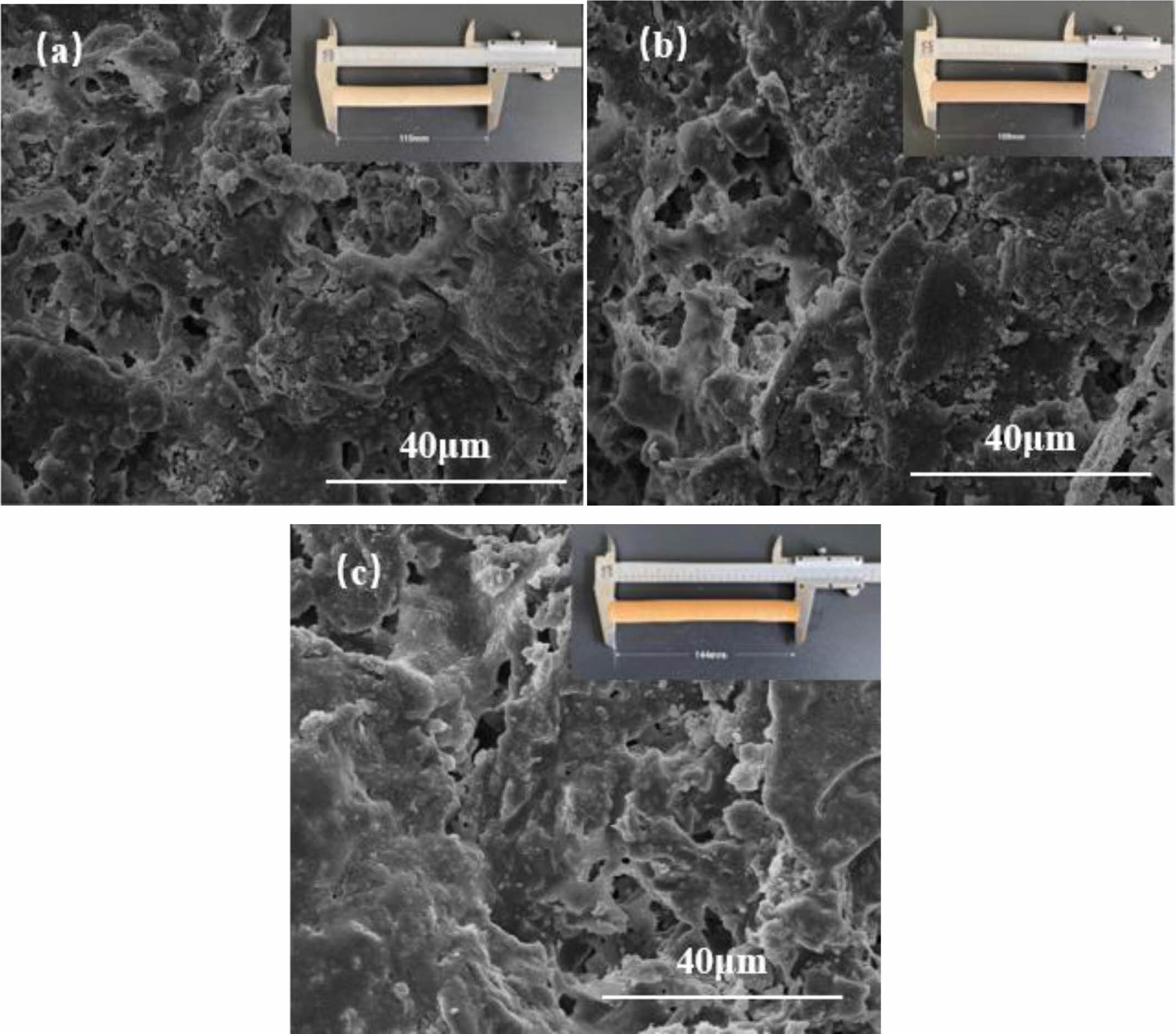
From Fig. 4, it can be seen that the microscopic morphology of the support varies considerably at different sintering temperatures. For C5 at 1100 °C, a pore structure formed by the accumulation of particles can be observed. The particle distribution is more uniform, but it can be seen that a glassy phase has appeared. With the increase of sintering temperature to 1200 ℃, Partial densification occurs, but some particles are still present. The neck connection increases and the pore structure is clearly visible. When the sintering temperature is increased to 1300 °C, the densification inside the support is obvious, the grain boundary is not obvious, and the pore structure is almost can be observed but significantly less. The phenomenon shows that the increase of temperature is conducive to the transformation and growth of the internal crystalline shape of the support, but too high a temperature can lead to the emergence of sintering densification phenomenon or the emergence of secondary sintering phenomenon, causing an increase in flexural strength and a decrease in porosity.
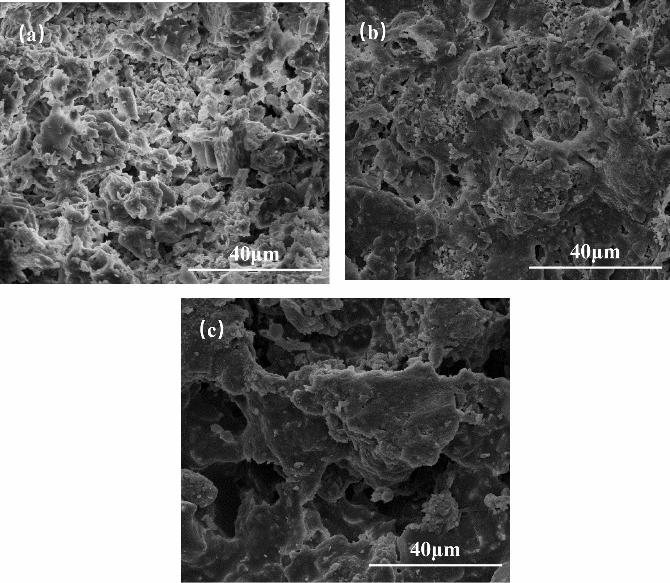
Fig. 5 shows SEM images for different CaCO3 contents at sintering temperatures at 1200 °C. The reason why C10 was not analyzed in the experiment was that the change of the crystal phase from C5 to C15 was not obvious enough to be representative. As can be seen in Fig. 5(a), a rod-like mullite crystal phase can be observed in C0. It indicates that the reaction of loess with bauxite is incomplete, and the reason may be that a small amount of liquid phase still exists at this temperature. At this time, the pore structure is mainly formed by the accumulation of particles, a small amount of necking occurs between some particles, and the grains are still in the growth stage. At the same temperature, the pore structure of C5 sample comes not only from the accumulation of particles but also from the crystalline phase structure generated during the formation of the secondary mullite phase. When the addition of CaCO3 reaches 15 wt%, the rod-like mullite phase and particles almost disappears. The massive aggregation of grains inside the support leads to the sintering of the liquid phase wrapped around the solid-state and densification.
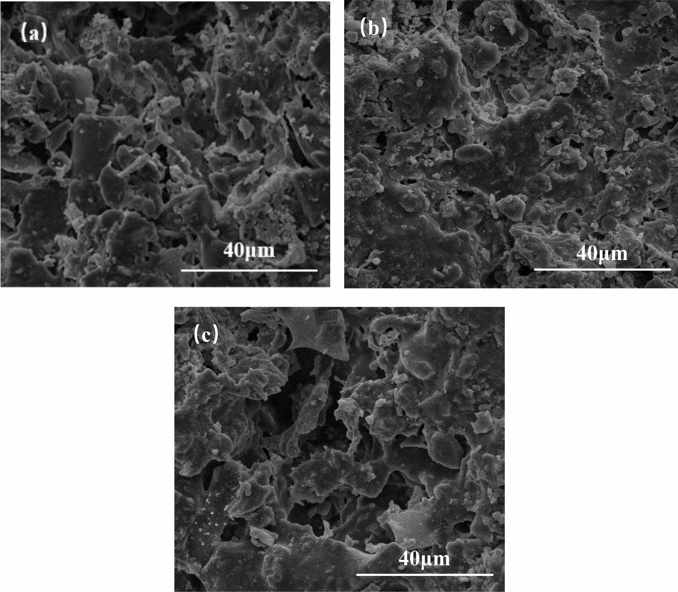
The surface microscopic morphology of C5 samples held at different sintering temperatures for 2 h was analyzed and the results are shown in Fig. 6. As can be seen from Fig. 6(a), when the temperature was 1100 °C, the grains were distributed in a punctiform pattern, with a large number of small particles and inconspicuous grain boundary bonding, a large number of holes but small pore size, only a small amount of sintered necking was observed to exist within the support, and the surface was rough and grainy, which indicated a low degree of sintering. As the temperature increases, at 1200 °C sintering (Fig. 6(b)), the grains grow in a rod-like distribution, the number of holes decreases but the diameter of the holes increases and the number of sintered necks increases, resulting in densification of the support, a gradual smoothing of the support surface and a change in color. When sintered at 1300 °C (Fig 6(c)), the grains inside the support were wrapped by glassy amorphous material to form a connected whole, and the surface of the support was smooth, indicating that as the temperature increased, the impurity minerals in the loess and bauxite melted and increased the degree of densification. Belibi P et al. [24] showed a similar phenomenon in the manufacture of microfiltration ceramic membranes using kaolinite-illite clay, a phenomenon attributed to the glassy phase formed by illite minerals, which reduces the porosity. QiLin Gu et al. [8] showed a similar phenomenon in the manufacture of microfiltration ceramic membranes using kaolinite-Al2O3, a phenomenon attributed to the glassy phase formed by illite minerals, which reduces the porosity. This electron microscope image confirms the phenomenon of decreasing porosity with increasing temperature, which is consistent with the results of the porosity test in section 3.5 Fig. 7(a).
Open porosity, flexural strength, Pure water flux of supports
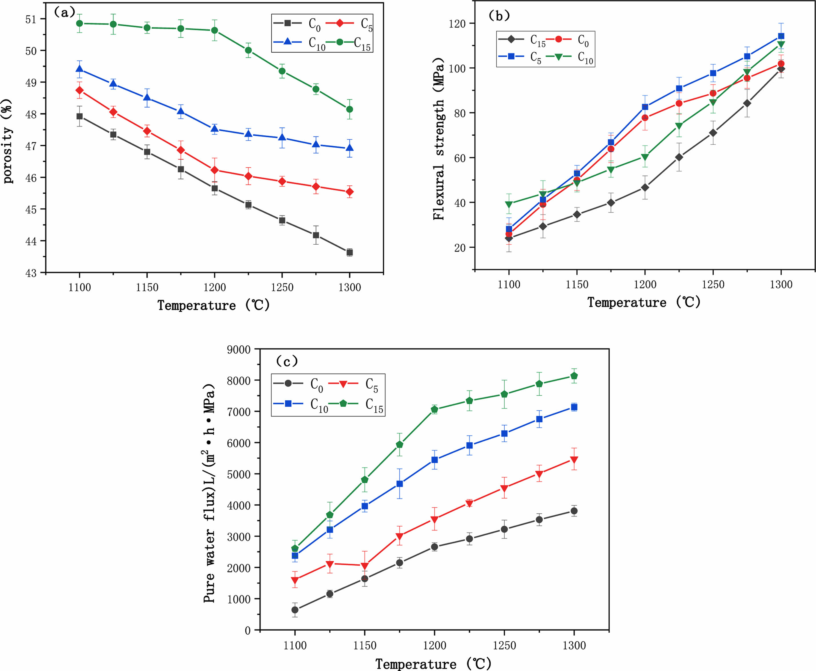
Fig. 7(a) shows the variation of porosity with temperature for different CaCO3 contents. With the increase of temperature, the porosity always kept a decreasing trend. 1100 °C, the CaCO3 addition increased from 0 wt% to 15 wt%, and the porosity also increased from 45.9% to 48.0%. Also observing the porosity curve at 15 wt% of CaCO3 content, it can be found that the porosity decreases from 48.9% to 39.1% as the sintering temperature increases from 1100 °C to 1300 °C. In common with the results of Harabi, A's study, the addition of CaCO3 was positively correlated with the porosity of the ceramic membrane support within a certain range [25]. The analysis shows that the porosity is generated by the decomposition of calcium carbonate during the sintering process.
Fig. 7(b) shows the variation of flexural strength with temperature for different CaCO3 contents. The flexural strength of the supports increased with the increase of sintering temperature. When the temperature increased from 1100 ℃ to 1300 ℃, the flexural strength of C5 support increased from 27.6 MPa to 113.4 MPa, and the flexural strength of C15 support increased from 24.0 MPa to 96.0 MPa. In the range of 1200~1300 ℃, the flexural strength of C5 support was always greater than that of C15. With Zhao [26] findings that the flexural strength is directly proportional to the sintering temperature. As the sintering temperature increases, the flexural strength increases sharply. The increase in flexural strength is mainly due to the increase in densification, which also causes a decrease in porosity. In this study, the flexural strength ranges from 24.1 to 110.9 MPa, which is better than that of mineral-based ceramic membrane supports and comparable to the flexural strength of ceramic membrane supports made of pure materials [27]. It is worth noting that at the same sintering temperature, with the increase of CaCO3 content, the flexural strength of the support increases first and then decreases, because the formation of a small amount of anfeldspar strengthens the neck connection structureand improves the flexural strength. However, when excessive CaCO3 is added, mullite and Cristobalite are excessively consumed to form anorthite, and the number of crystalline phases is reduced, leading to the reduction of flexural strength. In conclusion, compared with the content of pore-forming agent, the sintering temperature has a greater influence on the properties of the support.
Fig. 7(c) illustrates the pure water flux of the support body with different CaCO3 additions under constant pressure (0.1 MPa). As can be seen from the fig, the pure water flux of the support with the same CaCO3 content increases as the sintering temperature increases, which is due to the increase in temperature and the formation of a network of connected pores inside the support body with increased pore size, as will be demonstrated in the SEM plots. In particular, the pure water flux of C0 support increased from 732 L/(m2·h·MPa) to 3820 L/(m2·h·MPa) and the pure water flux of C15 support was always greater than C0 and increased from 2538 L/(m2·h·MPa) to 8202 L/(m2·h·MPa) due to the increase in CaCO3 content, which led to the increase in pore size [27]. Harabi et al. [25] prepared ceramic membranes from kaolin clay and by adding 5 to 20 wt% CaCO3 resulted in an increase in porosity from 51% to 55% and pore size from 5.2 μm to 8.6 μm, with a minimum porosity of 50% when CaCO3 was added at 25 wt%, and the support pore size continued to increase to 17.6 μm as CaCO3 content increased to 30 wt%.
In this study, the content of calcium carbonate was positively correlated with porosity, flexural strength and pure water flux. Sintering temperature shows a positive correlation with flexural strength and pure water flux, and a negative correlation with porosity. The reason for this phenomenon is that when the temperature rises to 1200 °C, although the porosity decreases, the internal liquid phase is not all formed. At this time, the support still has a stable pore structure, pure water flux although increased, but the rate of slowing down.In summary, the addition of calcium carbonate to the raw material facilitates the formation of pore structure, increases the pure water flux and helps to improve the flexural strength.
By performing a linear fit analysis of calcium carbonate content, sintering temperature versus flexural strength and porosity, we found that a good correlation between the flexural strength and porosity of the ceramic membrane supports for different calcium carbonate contents and sintering temperatures can be observed in Fig. 8(s1), Fig. 8(s2) and Table s1. This indicates that the calcium carbonate content and sintering temperature have a significant influence on the flexural strength and porosity of the supports. In order to investigate the preparation method to obtain the best proppant properties, central composite experiments were used to investigate.
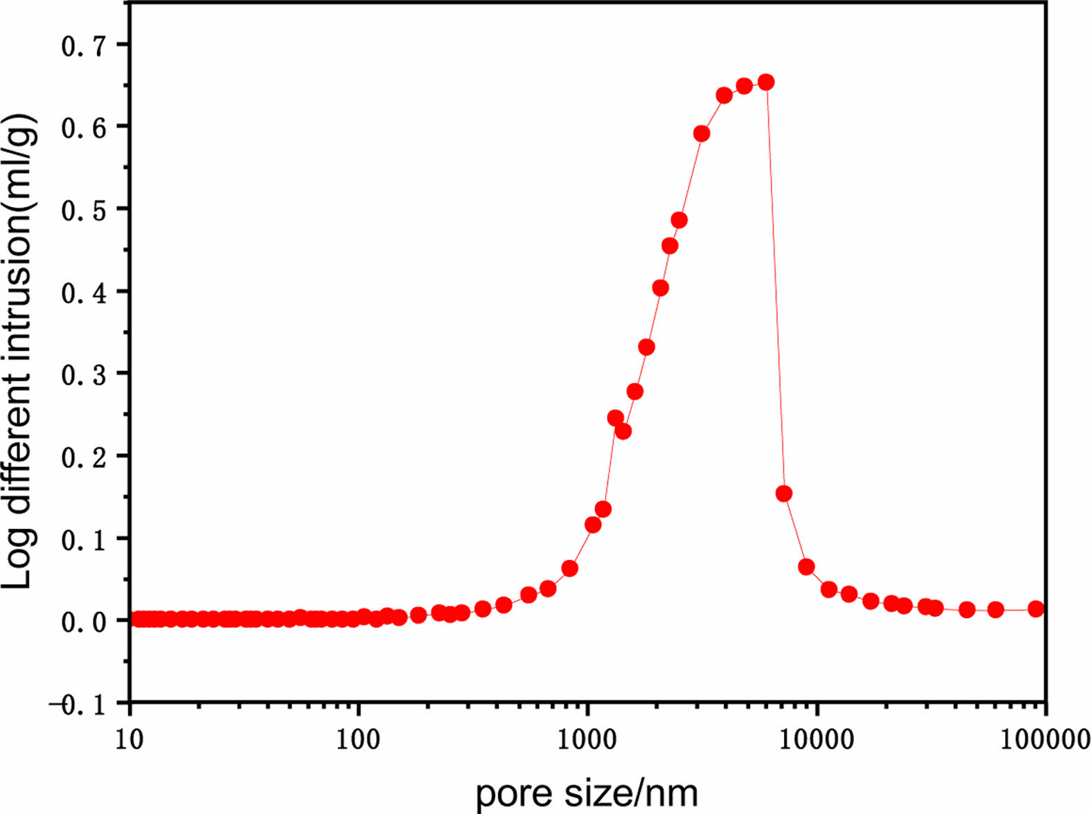
Fig. 8 shows the pore size distribution of ceramic membrane support when the sintering temperature is 1200 ℃ and the amount of calcium carbonate is 5 wt%. By the mercury injection meter test, the median pore size of the support is 1993.9 nm, the average pore size is 2504.7 nm, and the porosity is 49.9%.
Response surface optimization
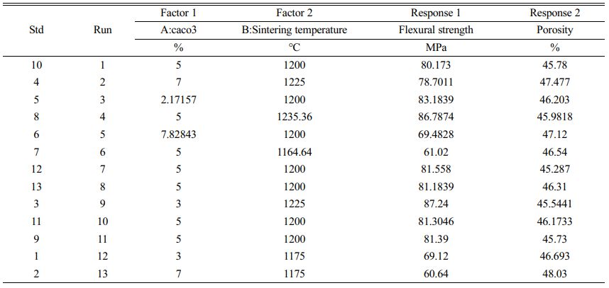
A central composite experiment was designed using Design Expert V8.0.6 software to investigate the effect of two factors affecting the amount of calcium carbonate (CaCO3) added and the sintering temperature on the porosity and flexural strength of the ceramic membrane support. By fitting the data to the analysis, the correlation between the influencing factors and the performance of the support was determined, and the best-predicted value within the range of values was derived. The experimental results are also analysed by combining the experimental data with the predicted values.
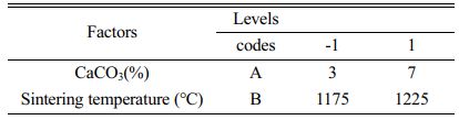
The central composite design experimental code and level table are shown in Table 3 The choice of calcium carbonate content and sintering temperature were both based on the variation in flexural strength and porosity. The optimum point was chosen to be a calcium carbonate content of 5% and a sintering temperature of 1200 °C. Table 4 Table 5
Flexural strength, porosity analysis
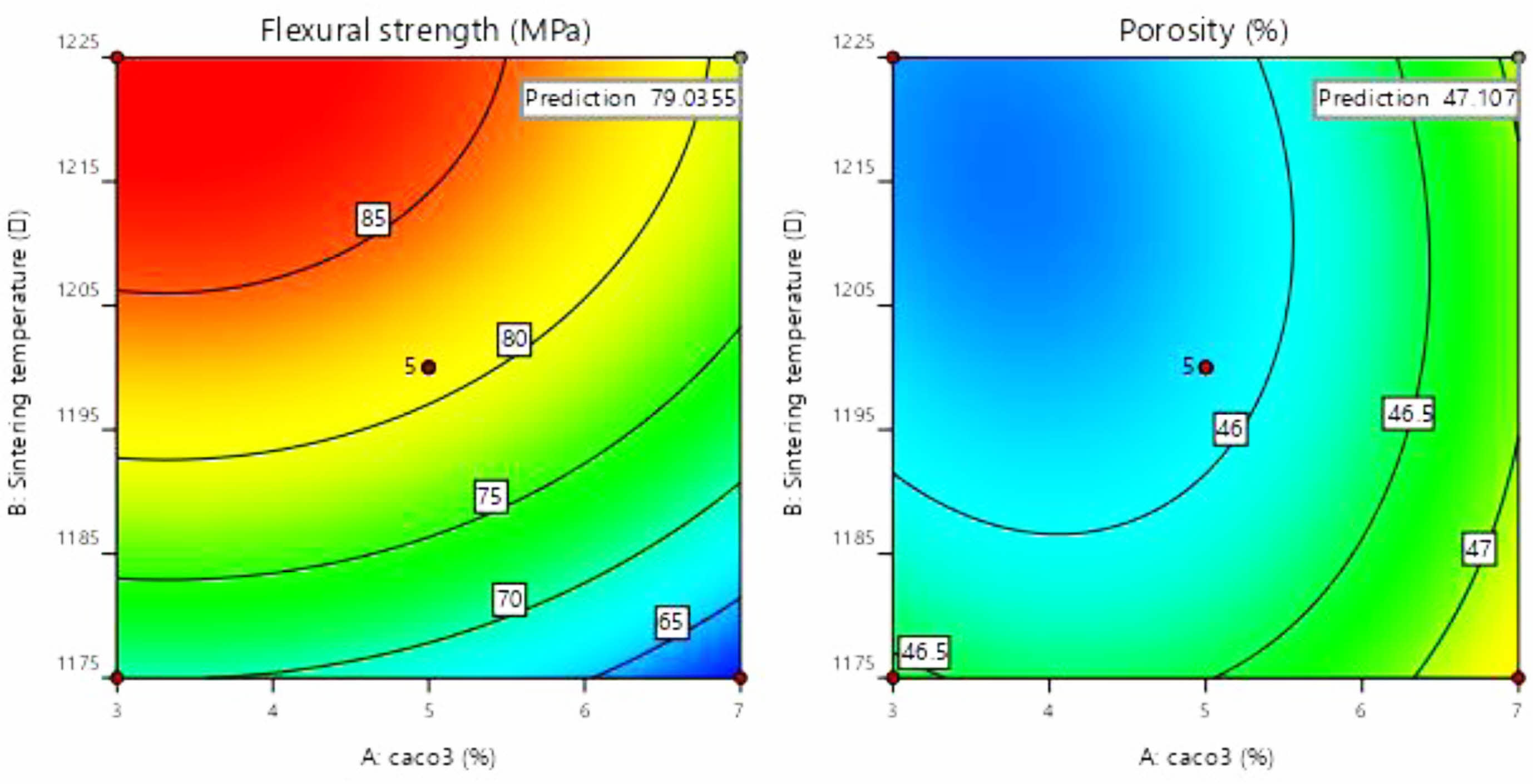
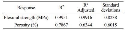
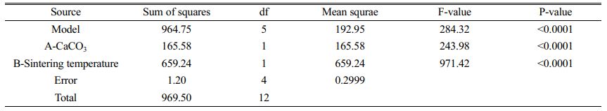
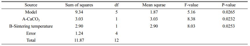
As can be seen in Fig. 9(a), the colour of the contours gradually becomes redder from the outer to the inner circle, indicating an increase in flexural strength caused by changes in the amount of calcium carbonate added and the sintering temperature. There are two possible reasons for this phenomenon: (1) As the sintering temperature increases, the occurrence of densification and liquefaction within the support body enhances the flexural strength of the support. (2) The increase in calcium carbonate content causes a change in the internal crystalline phase. At this point, analysis of the experimental results based on the model yielded a linear fit correlation coefficient R2 = 0.9951 for calcium carbonate content and sintering temperature against flexural strength, indicating a high correlation between the influencing factors and flexural strength. As can be seen from Table 6, P-value < 0.0001 indicates a very significant difference. And the larger F-value indicates that conditions A and B have good correlation with the flexural strength.
As seen in Fig. 9(b), the colour of the contours gradually becomes redder from the inner to the outer circle, indicating an increase in porosity due to changes in the amount of calcium carbonate added and the sintering temperature. The reason for the lack of reddening of the contour colour may be due to the limitations of the range of values taken for the amount of calcium carbonate added. When choosing the amount of calcium carbonate to be added, the middle value was chosen as the porosity and flexural strength are negatively correlated. Both porosity and flexural strength are ensured. However, it can still be observed from the contours that porosity varies with the two influencing factors. At this point, the linear fit correlation coefficient R2 = 0.7745 between the influencing factors and the experimental values of porosity correlates well. As can be seen from Table 6, the P-values are larger compared to Table 7. and the smaller F-values indicate that conditions A and B are poorly correlated with porosity compared to flexural strength. The reason for this is the change in calcium carbonate decomposition by heat and the change in the way the internal particles are connected during sintering.
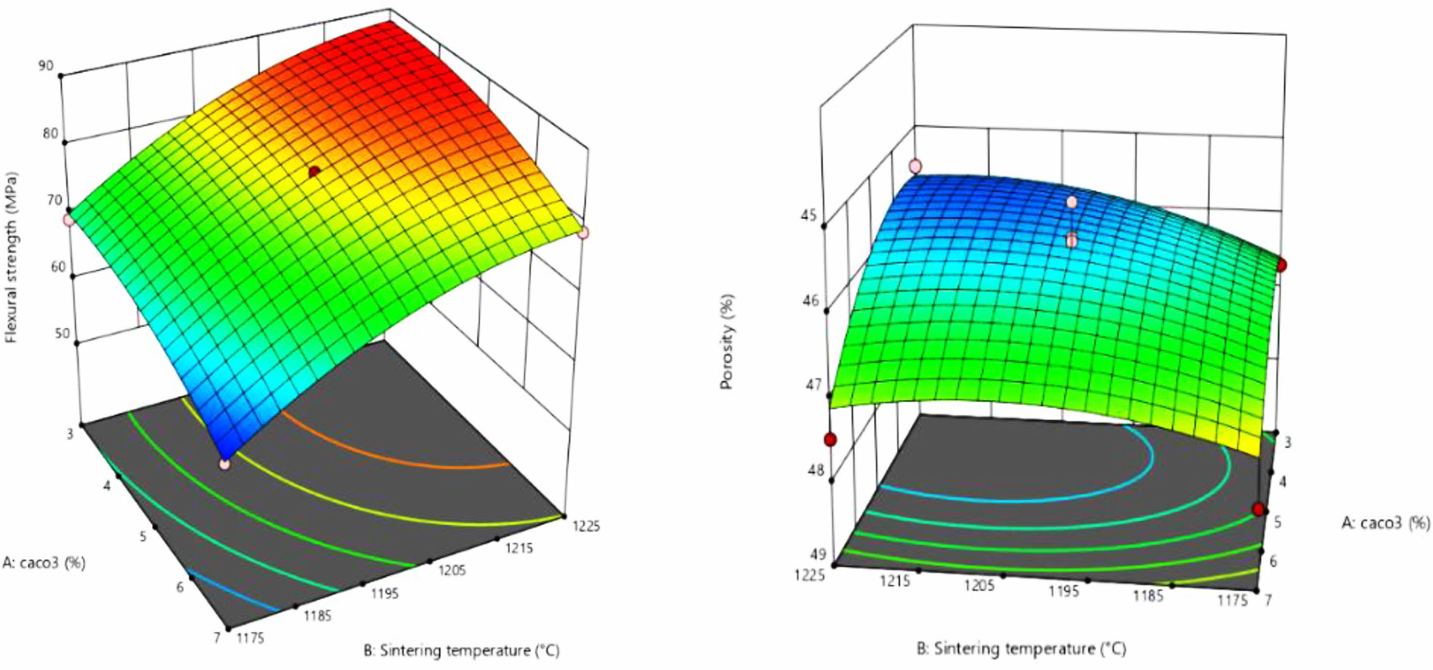
Fig. 10(a) Response surface for the relationship between calcium carbonate addition and sintering temperature on flexural strength (b) Response surface for the relationship between the two influencing factors on porosity. The convexity of the response surface is evident from the graph, indicating the relatively significant influence of each factor. The effect on flexural strength increases with increasing sintering temperature and calcium carbonate addition, as can be seen in Fig. 10(a). And in fig (b) it can be observed that the response surface still has obvious curvature changes, indicating that there is still a good correlation between the influencing factors and the porosity. The same knot over as that derived from the correlation coefficient R2 in the contour plot and linear fit. The best-fitting quadratic polynomial regression model was obtained from the response surface:


The effects of calcium carbonate content and sintering temperature on the flexural strength and porosity of the support were analysed. The linear relationship of the response surface was analysed to obtain the best predicted values in the given interval range. The flexural strength was 87.2 MPa and the porosity was 45.6% at a sintering temperature of 1215.91 °C for two calcium carbonate additions of 3.1%. The results were similar to the pre-selected optimum values at 5% calcium carbonate addition and a sintering temperature of 1200 °C.
|
Fig. 1 XRD patterns of Loess, Bauxite, Fly ash. |
|
Fig. 2 TG-DTG-DTA curves between room temperature and 1300 ℃ for C0 and C15 support. |
|
Fig. 3 XRD patterns of carriers with (a) C0, (b) C5, (c) C10 and (d) C15 contents sintered at different temperatures for 2 h. |
|
Fig. 4 Shows the SEM images of C5 support sintered at three different temperatures (a) 1100 ℃ (b) 1200 ℃ (c) 1300 ℃. |
|
Fig. 5 EM patterns of (a) C0, (b) C5, (c) C15 ceramic membranes sintered at 1200 ℃. |
|
Fig. 6 Surface SEM photos of supports sintered at (a) 1100 °C (b) 1200° (c) 1300 °C. |
|
Fig. 7 (a) porosity (b) flexural strength (c) pure water flux. |
|
Fig. 8 Optimum sample pore size distribution. |
|
Fig. 9 Contour map of flexural strength and porosity. |
|
Fig. 10 Flexural strength and porosity response surfaces. |
|
Table 3 Experiment design matrix and measured values of the considered responses. |
|
Table 5 Analysis of Variance (ANOVA) for respone surface for the Flexural strength. |
|
Table 7 Comparison of ceramic membrane support performance obtained in our work with those available in the literature. |
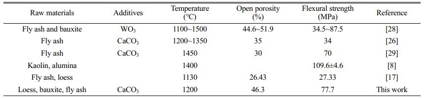
Taking the ceramic membrane support sintered at 1300 °C as an example and comparing it to other ceramic membranes reported in the literature, the ceramic membrane support prepared in this study using low-cost raw materials such as the natural minerals loess, bauxite and solid waste fly ash have the following advantages.
(1) Large reserves of raw materials, easy to obtain and low prices, which are conducive to reducing raw material costs.
(2) Relatively low sintering temperature, which is conducive to reducing energy consumption and lowering production costs.
(3) No harmful substances such as AlF, MoO3 and WO3 are added, making the preparation process green and environmentally friendly.
(4) The ceramic membrane support with high flux, good permeability, and high flexural strength can be obtained at a low temperature, which can be used for membrane coating or directly used as a microfiltration membrane for wastewater treatment.
In this study, loess, fly ash and bauxite were chosen as raw materials and CaCO3 was used as the poro-form agent. The effects of sintering temperature and the amount of poro-form agent added on the properties of the support were investigated.
(1) When the sintering temperature increased, the liquid phase was generated inside the support, which filled the pores and strengthened the bonding between the particles, reducing the porosity of the support but increasing the pore size and improving the pure water flux. At the same time, as the temperature rises, mullite and calcium feldspar crystalline phases are formed, increasing the flexural strength of the support.
(2) The addition of calcium carbonate increases the porosity of the support. When calcium carbonate is added at 5%, the rod or flake calcium feldspar crystals strengthen the neck connection structure between the grains and improve the fracture strength of the support. When 15% calcium carbonate is added, mullite is consumed and converted into calcium feldspar, reducing the flexural strength of the support body.
(3) Sintering in the range of 1100~1300 °C produced proppants with different properties. Among them, when the sintering temperature was 1200 °C and the CaCO3 addition was 5%, the pure water flux of the proppant was 4834 L/(m2·h·MPa), the flexural strength was 77.7 MPa, the porosity was 49.9%, and the main crystalline phases were mullite, calcium feldspar and corundum, with excellent physical and chemical properties.
- 1. Y. Bao, T.-T. Lim, R. Wang, R.D. Webster, and X. Hu, Chem. Eng. 343 (2018) 737-747.
-

- 2. Y. Bao, W.-J. Lee, T.-T. Lim, R. Wang, and X. Hu, Appl. Catal. B 254 (2019) 37-46.
-
- 3. K. Huang, B. Wang, S. Guo, and K. Li, Chem. Int. Ed. 57[42] (2018) 13892-13896.
-
- 4. K. Shima, Y. Funato, N. Sato, Y. Fukushima, T. Momose, and Y. Shimogaki, ACS Appl. Mater. Interfaces 12[45] (2020) 51016-51025.
-
- 5. B. Das, B. Chakrabarty, and P. Barkakati, Korean J. Chem. Eng. 34[10] (2017) 2559-2569.
-
- 6. F. Sandra, A. Ballestero, V.L.N. Guyen, M.N. Tsampas, P. Vernoux, C. Balan, Y. Iwamoto, U.B. Demirci, P. Miele, and S. Bernard, J. Membr. Sci. 501 (2016) 79-92.
-
- 7. H. Sun, Q. Lin, J.J. Li, and W. Wei, Sci. Technol. Food Ind. 38[07] (2017) 216-220.
- 8. Q. Gu, M. Kotobuki, C.H. Kirk, M. He, G.J.H. Lim, T.C.A. Ng, L. Zhang, H.Y. Ng, and J. Wang, ACS Appl. Mater. 13[24] (2021) 29199-29211.
-
- 9. Y. Dong, B. Lin, J. Zhou, X. Zhang, Y. Ling, X. Liu, G. Meng, and S. Hampshire, Mater. Charact. 62[4] (2011) 409-418.
-
- 10. M. Arzani, H. Mandavi, M.R. Sheikhi, T. Mohammadi, and O. Bakhtiari, Appl. Clay Sci. 161 (2018) 456-463.
-
- 11. Y. Li, X. Cheng, L. Gong, J. Feng, W. Cao, R. Zhang, and H. Zhang, J. Eur. Ceram. Soc. 35 (2015) 267-275.
-
- 12. H. Li-jun, L. Tao-yong, and L. An-xian, TNMSC 17 (2017) 60066-.
- 13. B. Qiu, N. Deng, Y. Zhang, and H. Wan, J. Clean Prod. 167 (2017) 1314-1324.
- 14. M.R. de la Rocha, M. Virginie, A. Khodakov, Pollo, L.D. Marcilio, and N.R. Tessaro, Isabel C. Ceram. Int. 47 (2020) 4187-4196.
-
- 15. B. Li, L. Guo, Z. Tong, Y.N. Guo, and K.P. Huang, J, Ceram, 42[05] (2021) 774-780.
- 16. Z. Shen, Y. Li, Z. Tong, X. Yan, and R.N. Sun, China Ceram. 56[09] (2020) 12-17.
- 17. Z. Tong, J.X. Zhang, X.J. Sun, B.W. Yang, and K.P. Huang, Mater. Guide 34 (2020) 12:7.
- 18. GB/T 1966-1996, Test method for porous ceramics with apparent porosity and capacitance. China: General Administration of State Standards, 1997.
- 19. GB/T 2833-1996. Test method for bending strength of ceramic pipes. Beijing: China Standard Publishing House, 1996
- 20. T. Zhi, K.P. Huang, B.W. Yang, and J.X. Zhang, Mater. Rev. 35.06 (2021) 6054-6059.
- 21. M. Fu, J. Liu, X. Dong, L. Zhu, Y. Dong, Hampshire, Stuart. J. Eur. Ceram. Soc. 39 (2019) 16.
-
- 22. S.Q. Lu and S.F. Wu, Ciesc. J. 66[08] (2015) 2895-2902.
-
- 23. B. Boudaira, A. Harabi, and F. Bouzerara, Desalin. Water Treat. 9 (2015) 142-148.
- 24. P.B. Belibi, M.M.G. Nguemtchouin, M. Rivallin, J.N. Nsami, J. Sieliechi, S. Cerneaux, M.B. Ngassoum, and M. Cretin, Ceram. Int. 41[2] (2015) 2752-2759.
- 25. A. Harabi, F. Zenikheri, and B. Boudaira, J. Eur. Ceram. Soc. 4[5] (2014) 1329-1340.
-
- 26. J. Hou, Z.W. Zhu, and Z.L. Wei, J. Alloy. Compd. 683 (2016) 474-480.
- 27. O. Bakhtiari, M. Samei, H. Taghikarimi, Mohammadi, Desalin. Water Treat. 36 (2011) 210-218.
-
- 28. M.M. Chen, L. Zhu, Y.C. Dong, L.L. Li, and J. Liu, Acs Sustain Chem. Eng. 4[4] (2016) 2098-2106.
-
- 29. F. Jiang, L.L. Zhang, Mukiza, Emile, Zhongwei, and D.Q. Cang, J. Alloy Compd. 749 (2018) 750-757.
-
 This Article
-
2023; 24(2): 308-320
Published on Apr 30, 2023
- 10.36410/jcpr.2023.24.2.308
- Received on Sep 13, 2022
- Revised on Oct 25, 2022
- Accepted on Nov 3, 2022
Services
- Abstract
introduction
experimental
results and discussion
comparation of performance of the ceramic membrane support reported in the literature
conclusion
- References
- Full Text PDF
Shared
Correspondence to
- Zhi Tong
-
School of Environmental and Chemical Engineering, Xi’an Polytechnic University, Xi’an 710000, China
Tel : 029-62779281 Fax: 029-62779281 - E-mail: 1018915428@qq.com
Clean-Energy Research Institute(CRI), Hanyang University, 222, Wangsimni-ro, Seongdong-gu, Seoul, 04763, Korea
E-mail: jcpr@hanyang.ac.kr