


- A review on the failure behavior and countermeasures of thermal barrier coatings
Jiahang Liua, Zhe Lua,*, Yanwen Zhoua, Jing Zhangb and Guanlin Lyuc
aSchool of Materials and Metallurgical Engineering, University of Science and Technology Liaoning, Anshan 114051, China
bDepartment of Mechanical Engineering, Indiana University-Purdue University Indianapolis, Indianapolis, IN 6202, USA
cKey Lab of New Ceramics and Fine Processing, School of Materials Science and Engineering, Tsinghua University, Beijing 100084, ChinaThis article is an open access article distributed under the terms of the Creative Commons Attribution Non-Commercial License (http://creativecommons.org/licenses/by-nc/4.0) which permits unrestricted non-commercial use, distribution, and reproduction in any medium, provided the original work is properly cited.
Thermal barrier coatings are widely used in high-temperature components in aircraft thrusters, power generation, and marine engines, enabling gas turbines to operate at elevated temperatures for extended periods by reducing the superalloys' surface temperature. During service, high-temperature oxidation, hot corrosion, and sintering occur inside the thermal barrier coatings, resulting in changes in the macro and microstructure of the coatings, and thermal-mechanical properties degradation, eventually leading to coating failure. The main factors that lead to the failure of thermal barrier coatings and affect the life of thermal barrier coatings are reviewed, including the formation of thermally grown oxides on the surface of the bond coat, the corrosion caused by the deposits on the surface of the coating and the sintering of the high-temperature ceramic layer, and the failure mechanism of the coating is analyzed. The countermeasures to prolong the service life of coatings are reviewed from thermal barrier coating materials, coating structure, coating preparation methods, and post-treatment
Keywords: Thermal barrier coatings, Failure behavior, Countermeasures, Bond coat, Ceramic layer
As aerospace technology continues to advance, turbine engines are moving towards higher thrust-to-weight ratios and higher fuel efficiency, which requires increasing turbine front inlet temperatures [1, 2]. The concept of thermal barrier coatings (TBCs) was developed by NASA in the 1950s to ensure that the hot end components inside the engine would operate consistently over long periods in high-temperature environments [3, 4]. The TBCs are usually made up of the following four components: 1) nickel-based or cobalt-based high-temperature alloy substrates; 2) metallic bond coat with excellent oxidation resistance; 3) thermally grown oxides (TGO) layer formed in the high-temperature environment, and 4) a ceramic topcoat deposited by air plasma spraying or electron beam-physical vapor deposition processes [5-7]. The primary function of the metallic bond coat is to improve the physical compatibility between the metal substrate and the ceramic coat, improve the bonding strength of the ceramic layer and enhance the oxidation resistance of the metal substrate. Ceramic coatings play a significant role in heat insulation but also need to prevent the penetration of external corrosion and effectively resist high-temperature flame erosion [8, 9].
TBCs work in complex high-temperature environments, so thermal conductivity and service life become the most fundamental characteristics for evaluating the performance of TBCs. Thermal conductivity is one of the intuitive embodiments of the thermal insulation function of TBCs. The service life is a critical evaluation index to ensure the safe and reliable service of TBCs. Due to the complex working environment of the thermal barrier coating, the formation of TGO on the surface of the bond coat, the sintering inside the ceramic layer, and the deposition of corrosive substances on the surface of the ceramic layer are the main factors leading to the failure of the coating [10-16]. In order to optimize the performance of the TBCs, researchers improve the service life of TBCs at high temperatures from the aspects of coating material design, preparation method, and surface treatment.
The objective of this review is to present an overview of the failure behavior of TBCs in high-temperature environments and the countermeasures to improve the service life of coatings. The article presents the effects of TGO growth, ceramic layer sintering, and molten corrosion on the service life of TBCs, and the optimization methods of TBCs are reviewed from the aspects of coating material design, coating preparation, and coating post-treatment.
As the intermediate layer between the metal substrate and the ceramic layer, the bond coat can enhance the mechanical bonding strength, alleviate the significant thermal expansion coefficient difference between the ceramic layer and the metal substrate, and reduce the thermal expansion stress in the coating under a high-temperature environment [17, 18]. At the same time, the metal elements in the bond coat can react with the oxygen diffused into the coating in a high-temperature environment to avoid the oxidation of the bottom superalloy [19]. Currently, the widely used MCrAlY (M=Ni, Co) metallic bond coat in the field of TBCs is mainly composed of β-NiAl and γ-Ni(CoCr) phases [20]. Ni and Co elements in MCrAlY can improve the metallic bond coat's oxidation and corrosion resistance; Cr can reduce the critical Al content required for the formation of dense α-Al2O3 on the metallic bond coat's surface, improve Al diffusion's ability to penetrate the metallic bond coat, and slow down the reaction of Ni, Co, and O2 to form spinel oxides [21-23]. At present, atmospheric plasma spraying (APS) has been applied to prepare metallic bond coat due to its low preparation cost, convenient operation process, and wide parameter adjustment [24, 25]. However, in the process of APS, the bond coat powder will react with oxygen in the high-temperature plasma jet, resulting in internal oxides in the as-sprayed bond coat. The formation of internal oxide will reduce the content of Al in the bond coat, resulting in Cr2O3, NiO, (Ni, Co)(Cr, Al)2O4, and other two-stage oxidation products appearing in the first stage of oxidation, reducing the service life of TBCs. In addition, the metallic bond coat prepared by APS has a large surface roughness [26]. Although a large roughness can enhance the mechanical interlocking between the bond coat and the ceramic layer and improve the interlayer bonding strength, in the study of Busso et al. [27] and Taylor et al. [28] on the roughness of the metal bond coat, they found that a sizeable interfacial roughness would increase the diffusion rate of Cr and Ni at the bulge position. Finally, the non-uniform thickness of TGO formed at the bond coat/ceramic layer interface reduced the service life of the TBCs. Liu et al. [29] used a cohesive force model and TGO non-uniform growth subroutine to simulate the effect of TGO growth on the internal stress of the coating. The results showed that the non-uniform TGO during thermal cycling made the internal stress of the coating reach 162.41 MPa, which was much higher than that of the uniform TGO of 113.82 MPa. In addition, Zhou et al. [30] analyzed the effect of TGO on the service life of APS-TBCs. The results showed that the increase of TGO thickness would lead to the change of stress in the coating, resulting in crack propagation and visible delamination in the ceramic layer. To reduce the negative impact of non-uniform growth of TGO, researchers began to improve oxidation resistance through preparation methods, material composition designs, and surface treatment of bond coat.
Improvement of preparation methods
To avoid the oxidation of the bonding layer powder during the APS, researchers began to explore other preparation methods to obtain a metallic bond coat with a smooth surface, dense interior, and no oxidation. New preparation methods mainly include high-velocity oxy-fuel spraying (HVOF) and cold gas dynamic spraying (CGDS).
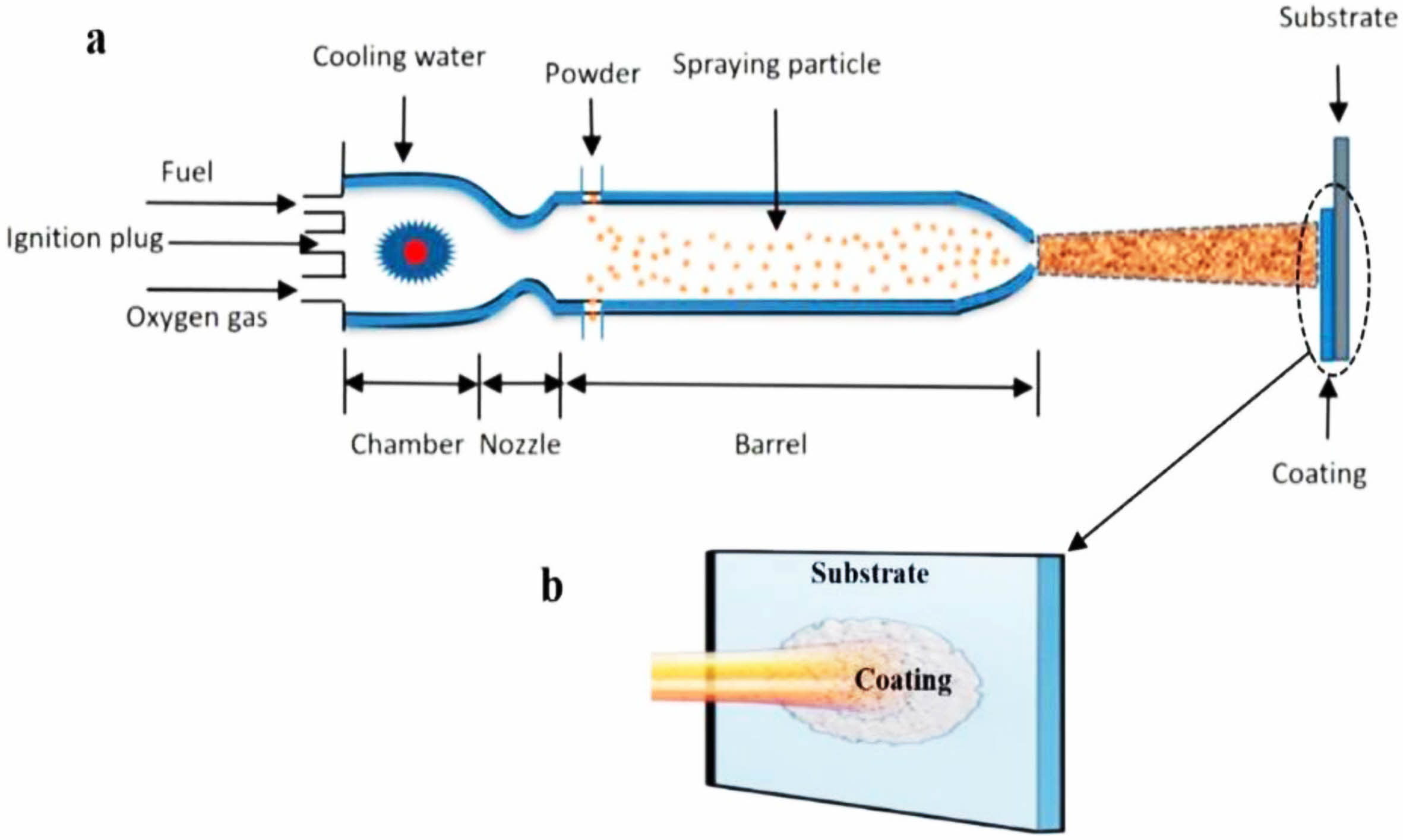
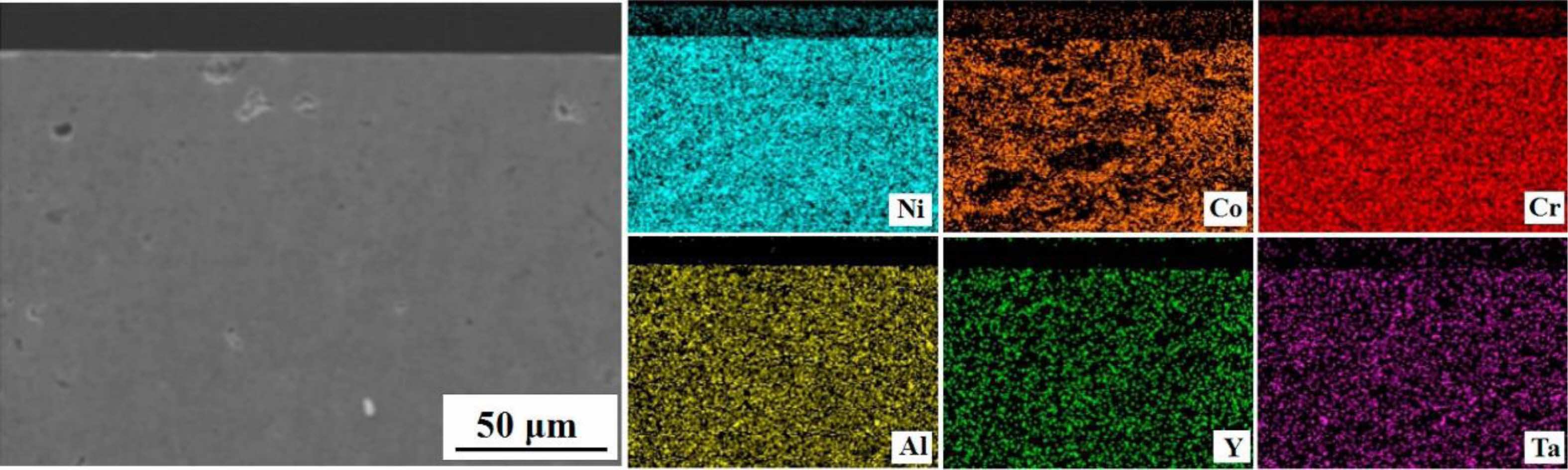
High-velocity oxy-fuel spraying is a thermal spraying process proposed in the 1980s. Its preparation principle is shown in Fig. 1 [31]. Combustible gases such as H2, C3H3, and C3H6, or liquid fuels such as kerosene and alcohol were mixed with high-pressure oxygen to ignite in the combustion chamber. The rapidly expanding high-temperature gas fully heated the bond coat powder and accelerated the molten powder to 300-650 m/s to prepare the metallic bond coat with high bonding strength and dense internal structure. Hao et al. [32] prepared the NiCoCrAlYTa metal layer using the HVOF method and observed its cross-sectional micro- scopic morphology. The results were shown in Fig. 2. The bond coat had a dense internal structure with uniform distribution of elements and no bias clustering, indicating that no oxidation behavior occurred during the preparation process. Lu et al. [33] prepared NiCrCoAlY bond coats using the APS and HVOF methods, respectively, and prepared YSZ ceramic layers on the surface of the two bond coats. The two TBCs were subjected to thermal cycling tests at 1100 °C to compare the effects of the two bond coats on the TBCs' service life. Based on the test results, due to the dense microstructure inside the HVOF bond coat effectively slowing down the diffusion of oxygen and reducing the growth rate of TGO, the thermal cycle life of the TBCs was substantially improved.
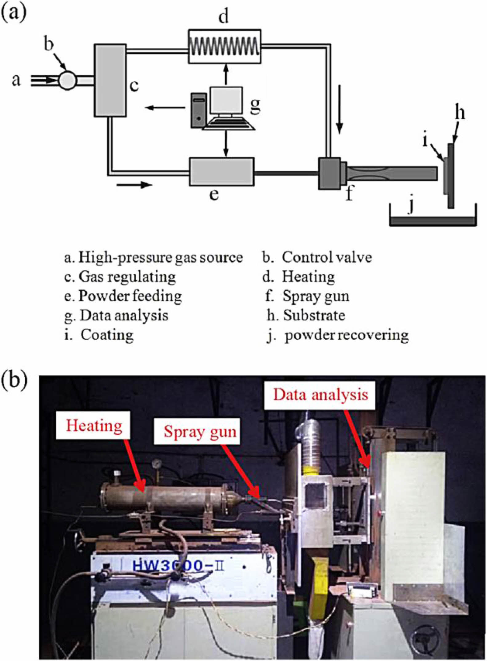
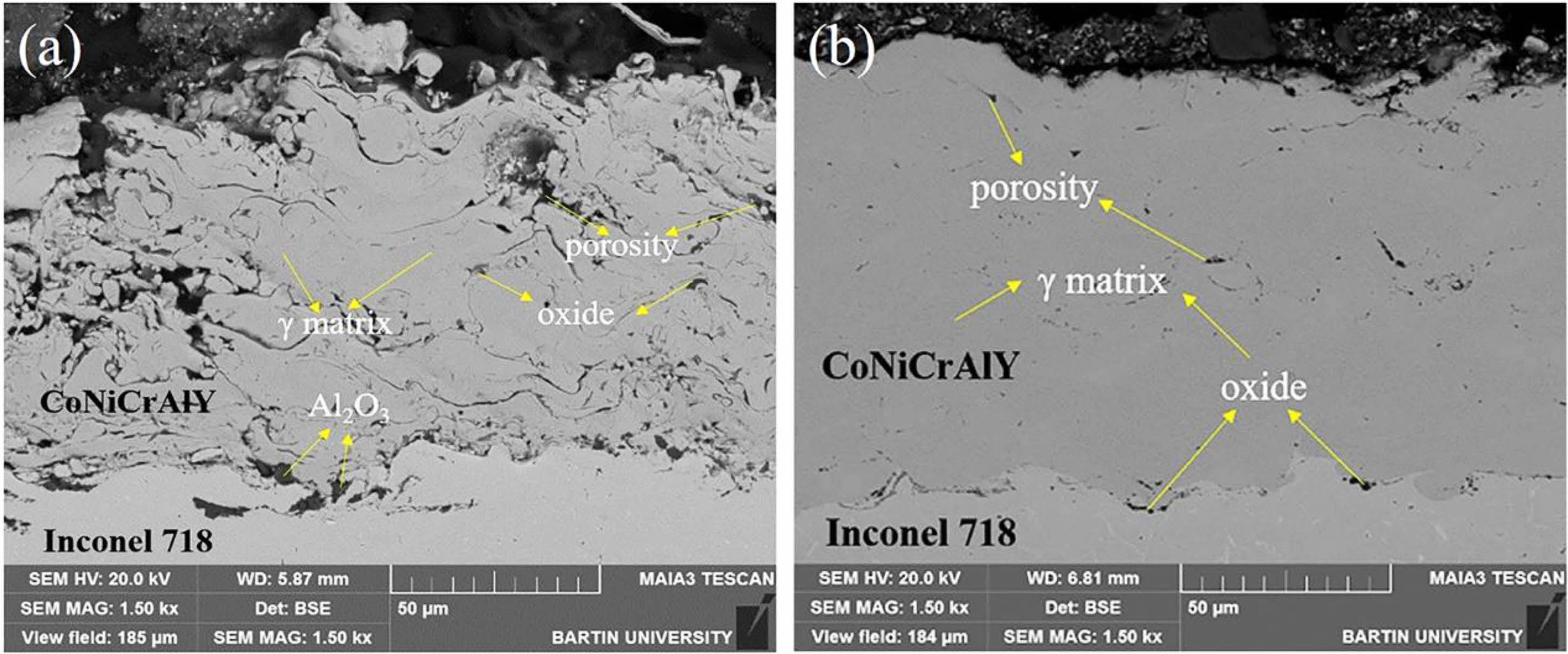
Cold gas dynamic spraying is a coating preparation process proposed in the 1990s, and its preparation principle is shown in Fig. 3 [34]. In contrast to thermal spraying, cold gas dynamic spraying carries the powder particles of the bond coat to the surface of the metal substrate through high-speed carrier air. The powder particles with significant kinetic energy will cause plastic deformation when they touch the metal substrate, thus forming a dense bond coat. Since the metal powder is not heated to a molten state during the cold gas powder coating process, the formation of oxides in the prepared bond coat is avoided, and the high Al content in the bond coat is retained. Karaoglanli et al. [35] prepared CoNiCrAlY bond coats using CGDS and APS, respectively, and compared the internal micro- structure of the two bond coats, as shown in Fig. 4. Compared with the APS-bond coat, the CGDS-bond coat had significantly lower oxide and porosity content internally. It had lower surface roughness, which was beneficial for reducing the diffusion rate of Al, reducing the growth rate of TGO in a high-temperature environment, and improving the oxidation resistance of the thermal barrier coating.
Composition design of the bond coats
Since the MCrAlY currently used are suitable for environments below 1100 ℃, there is a need to develop metallic bond coat materials that are suitable for higher temperature environments and to ensure that the new materials have a slow oxidation rate that can effectively improve the high-temperature service life of the TBCs [36, 37]. Compared with conventional MCrAlY, NiAl is considered a new bond coat material with excellent potential for use due to its higher melting point, high-temperature oxidation resistance, and low cost [38-40]. However, the mechanical bonding strength between NiAl and TGO weakens with increasing holding time, causing it to delaminate during cooling, so its composition needs to be designed to improve its performance [41]. Gleeson et al. [42] used Pt elements to modify the NiAl bond coat. They analyzed the isothermal oxidation behavior of the Pt-NiAl bond coat. The results showed that the increase of Pt content caused the formation of a dense Al2O3 thin layer on the surface of the bond coat, which could effectively inhibit the diffusion of external oxygen to the inside of the bond coat and improve the resistance of the bond coat to high-temperature oxidation. In addition, Hou et al. [43] analyzed the bonding strength between the Pt-NiAl bond coat and TGO. The results showed that the Pt element could inhibit the segregation of sulfur elements between the TGO/bond coat and improve the adhesion ability of TGO. Zhao et al. [44] chose to dope Lu and Hf elements into NiAl material, respectively. To improve the oxidation behavior of the NiAl bond coat during thermal spraying and compare the thermal cycle life with NiCoCrAlY at an 1150 ℃ environment. The results showed that the doping of active elements could effectively slow down the growth rate of TGO and improve the thermal cycle life of TBCs. However, Li et al. [45] researched La-doped NiAl and found that not all active elements can improve the oxidation resistance of the material. The thermal cycle life of the coating was only 100 times due to the severe oxidation of the La-NiAl bond coat during the thermal cycle, which is far less than that of the NiAl TBC doped with Dy, Hf, Y, and other active elements.
In addition to NiAl bonding layer materials, high entropy metal materials doped with active elements have also become bond coat materials with excellent application potential. At the beginning of the 21st century, Yeh et al. [46] proposed the concept of high-entropy alloys. Compared with the traditional single-principal and double-principal element alloys, high-entropy alloys have the following four effects [47-50]: 1) High entropy effect in thermodynamics. High mixing entropy increases the solid solubility of the alloy, which is conducive to forming a solid solution phase structure; 2) Lattice distortion effect in structure. Various atoms in the high-entropy solid solution randomly occupy the lattice position of the crystal, causing severe distortion of the lattice and affecting the mechanical, thermal, and chemical properties of the high-entropy alloy; 3) Dynamic hysteresis diffusion effect. The interaction between different components and lattice distortion will affect the synergistic diffusion between components, limiting the effective diffusion rate, and 4) The cocktail effect on performance. Various elements' essential characteristics and interactions make high entropy alloys present a compound effect. High entropy alloys have attracted much attention due to their unique structural composition and excellent room/high-temperature mechanical properties. Zhao and Lu et al. [21, 51-53] designed and prepared NiCoCrAlFe high entropy alloys modified by active elements Y and Hf and analyzed their oxidation resistance at 1100 ℃. The results showed that the Al2O3 thin layer can grow uniformly and continuously during long-term oxidation at 1100 ℃, and the thickness of TGO is only 4.6 μm after 1000 h. And there is no interface defect in TGO, which can ensure the excellent bonding strength of the interlayer interface. In addition, by observing the microstructure of TGO after isothermal oxidation of Y/Hf-AlCoCrFeNi and traditional NiCoCrAl at 1100 ℃ for 500 h, it was found that (Co,Ni)(Al,Cr)2O4 spinel oxides appeared on the surface of NiCoCrAl, indicating that the bond coat entered the second stage of oxidation. However, only early oxidation product (Al,Cr)2O3 was detected on the surface of the high entropy bond coat, indicating that the design of a high entropy metal bond coat can effectively slow the diffusion of oxygen to the bond coat and reduce the growth rate of TGO. Improve high-temperature oxidation resistance of TBCs.
Surface treatment of bond coats
When the TBCs work at a high temperature, Al in the metal bond coat will diffuse outward, forming a dense layer of Al2O3 between the ceramic layer and the metallic bond coat. The TGO layer with uniform thickness and high α-Al2O3 content can effectively improve the oxidation resistance of the bonding layer and prolong the service life of the thermal barrier coating [54]. At the same time, the growth of TGO will change the interface structure between the bond coat and the ceramic layer. The failure of most TBCs is related to the growth morphology of TGO and internal stress development. In the service process of the coating, the internal stress of TGO will increase significantly [55]. When the stress in these areas exceeds its limit, the crack will form and propagate at the defect, and the coating will fail. The results showed that the interface morphology of TBCs was an essential factor affecting the growth and internal stress of TGO [56]. Surface treatment is an effective measure to improve the surface morphology and TGO growth behavior of the adhesive layer, which can effectively improve the thermal barrier coating service life. At present, the widely used bond coat treatment methods include preheating treatment and laser surface modification.
Preheating treatment of bond coat is to place thermal barrier coating in a vacuum or inert gas environment for heat preservation. Preheating treatment can improve the internal microstructure of the bond coat, optimize the growth behavior of TGO and prolong the service life of the coating. Regarding the phase composition of the bond coat, relevant studies pointed out that with the increase in vacuum heat treatment temperature, the grain size in the NiCrAlY bond coat increased, and the residual stress in the coating was released. After vacuum heat treatment at 1050 °C × 4 h for the CoNiCrAlY bond coat, the phase structure of the coating was transformed from γ phase to γ+β phase, which was conducive to the slow and uniform diffusion of the Al element and improved the oxidation resistance of the bond layer [57]. In terms of the internal microstructure of the bond coat, preheating treatment can improve the crystallinity of the bond coat powder, effectively seal the defects such as interlayer pores and cracks, and reduce the diffusion of oxygen in the bond layer. Meng et al. [58] analyzed the microstructure of prepared and vacuum-treated MCrAlY coatings, as shown in Fig. 5. The pores and cracks in the interlayer will be closed. This relatively dense microstructure reduces the aluminum loss caused by internal oxidation, which is beneficial to the aluminum supplement on the surface of the bond coat. Gao et al. [57] Prepared a two-layer structure bond coat by HVOF and APS. The bond coat was vacuum heat treated to study the oxidation resistance of the TBCs. The results showed that the content of β-(Co,Ni)Al phase increased from 13.91% to 27.78% after 1050 ℃ × 3 h vacuum heat treatment and the distribution was more homogeneous. The roughness of the HVOF-sprayed bond coating is decreased by vacuum heat treatment. The roughness of the vacuum heat-treated bond coat increased from 7.2 μm to 10.4 μm by introducing the APS layer. The bonding strength of TBC was up to 39.4 MPa. Meng et al. [59] preheated the surface of the MCrAlY bond coat prepared by LPPS and APS in an inert gas environment. The results showed that α-Al2O3 particles formed on the surface of the bond coat increased the oxidation resistance of the two bond coats by three times and eight times, respectively. The existence of α-Al2O3 particles can effectively inhibit the formation of spinel oxides under a high-temperature environment, reduce the diffusion rate of metal ions such as Ni and Cr, and ultimately reduce the growth rate of TGO.
Laser surface remelting is a rapid solidification technology developed in the 1980s for surface modification of materials. Without any addition of materials, this technology uses high-energy laser beams to melt the coating surface rapidly and cool it to refine the coating grain, reduce the pores and cracks of the coating, and improve the surface hardness, wear resistance, and fatigue life of the coating. Currently, the research on the effect of laser remelting on reducing residual stresses, pores, cracks, surface roughness, and grain refinement of coating is relatively mature [60, 61]. At present, many scholars have used this technology for the post-processing of remanufacturing alloy layers. Laser surface remelting technology can effectively improve the surface structure of the adhesive layer. In this process, the surface of the adhesive layer is rapidly melted and solidified, forming a dense, uniform, crack-free, and pore-free layer. In addition, there is a high aluminum-rich phase in the remelting layer. The TGO formed on the remelting layer surface is mainly composed of α-Al2O3, and no spinel oxide was found [62, 63]. Kwakernaak et al. [64] analyzed the phase composition of the NiCoCrAlY bond coat after laser surface melting. The research found that the remelted layer contained a high volume fraction of the β phase. The β phase contained a small amount of Al and more Cr and has a lower lattice parameter. The investigation by Luo et al. [65] revealed that in the initial oxidation stage, the β phase in the laser melting layer could rapidly form α-Al2O3 and slowly form a dense TGO layer during the subsequent oxidation process. Therefore, laser remelting on the surface of the bond coat can effectively improve the TBC's oxidation resistance, enhance the bond coat's peel resistance, and improve the high-temperature service life of the TBCs.
|
Fig. 1 (a) Schematic diagram of HVOF and (b) status of the substrate with coating [31]. |
|
Fig. 2 Element mappings of the cross-section of as-sprayed NiCoCrAlYTa coating determined by SEM-EDS [32]. |
|
Fig. 3 (a) Schematic representation of CGDS and (b) Picture of CGDS system [34]. |
|
Fig. 4 Cross sectional SEM image of as-sprayed APS CoNiCrAlY bond coating (a) and CGDS CoNiCrAlY bond coating. |
|
Fig. 5 Cross-sectional microstructure of the as-sprayed CoNiCrAlY bond coats: (a) BSE image; (b), (c) EDS results of (a) [58]. |
When TBCs work in a high-temperature environment, the solid corrosion salt on the surface of the coating will be transformed into a molten state. The molten salt penetrates the coating through microcracks and pores. It reacts with ceramic materials, resulting in premature failure of the coating at high temperatures [66, 67]. The hot corrosion behavior of TBCs mainly includes three kinds:
1) The first is CaO-MgO-Al2O3-SiO2 corrosion. When the dust concentration in the working environment of the turbine engine is high, the engine's inlet will inhale particles such as dust and volcanic ash, which are mainly composed of CMAS [68-70]. When the servicing temperature is higher than 1200 °C, the particles deposited on the engine blades begin to sinter, melt and flow viscously through microcracks and pores to the inside of the coating [68]. The damage to TBCs by CMAS at high temperatures is mainly divided into two aspects: thermomechanical and thermochemical. In the thermomechanical aspect, CMAS solidifies in cracks and pores of TBCs due to lower blade temperature when the engine is extinguished. Due to the difference in thermal expansion coefficients between ceramic materials and CMAS, the coating accumulates a large amount of stress during the cooling process. In addition, the diffusion of Si accelerates the sintering of ceramic coatings, increases the elastic modulus of coatings, and decreases strain tolerance. The strain space inside the coating is reduced, resulting in essential changes in the energy release rate, forming a large number of cracks inside the coating and eventually leading to coating failure. This series of internal coating microstructure and stress changes will make the coating in the thermal cycle process form many cracks, resulting in coating failure [71-73]. In the thermochemical aspect, rare earth oxides in ceramic materials react with CMAS and form corrosion products such as apatite and aluminate. The consumption of rare earth oxides leads to the formation of a poor-rare earth area in the coating, resulting in the instability, dissolution, and reprecipitation of t-ZrO2 into m-ZrO2. The phase transformation of ZrO2 will be accompanied by 3-5% volume expansion, resulting in cracks in the coating. Eventually, the coating will fall off. [74]
2) The second is Na2SO4+V2O5 corrosion. Bahamirian et al. [75,76] analyzed the sediment on the turbine blade surface. They found that insufficient combustion of fuel leaves two salts, Na2SO4 and V2O5, on the blade surface. Unlike CMAS corrosion, the melting points of Na2SO4 and V2O5 are 884 °C and 690 °C, respectively, so the two salts have different corrosion behaviors of TBCs in different temperature environments. When the service temperature is 700-900 °C, only V2O5 reacts with the ceramic, and Na2SO4 is still deposited on the ceramic layer [77]. When the operating temperature is higher than 900 °C, Na2SO4 reacts with V2O5 to form NaVO3, then NaVO3 reacts with ceramic materials as the intermediate reactant. The specific reaction processes can be expressed as the following reaction [78]: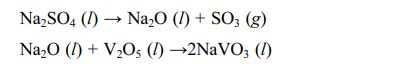
Since the melting point of NaVO3 is 610 °C, it will rapidly react with the rare earth oxides in the ceramic layer at this temperature. The consumption of rare earth oxides will lead to many t-ZrO2 residues in the coating. When the temperature exceeds 1200 °C, the t-ZrO2 undergoes phase transformation. It leads to premature failure of the coating.
3) The third is CMAS+NaVO3 corrosion. Marine engines deposit a mixture of CMAS and NaVO3 on the surface of hot end components during operation. Guo et al. [79] found that when the doping content of NaVO3 was 10 wt%, the mixed corrosives wholly transformed into a molten state at 1200 °C, and NaVO3 significantly improved the fluidity and crystallization ability of the CMAS, accelerated the penetration of the molten salt in TBC, resulting in severe corrosion inside the coating. Zhang et al. [80] investigated the crystallization behavior of CMAS and CMAS+NaVO3 to potentially clarify their corrosion mechanisms to TBCs. The results showed that CMAS crystallized at 1200 ℃ to form CaMgSi2O6, CaSiO3, and CaAl2Si2O8, while CMAS+NaVO3 was molten at 1200 ℃ without any crystallization formation. It indicated that the mixing of NaVO3 decreased the melting point of CMAS and increased the corrosion of the coating by CMAS. Currently, researchers optimized the coating structure and ceramic materials to improve the corrosion resistance of TBCs at high temperatures.
Structure optimization of coating
The corrosive deposited on the surface of the TBCs will transform into a molten state under a high-temperature environment and flow into the coating through the microcracks and pores on the surface of the ceramic layer. Therefore, researchers propose to optimize the structure of the TBCs to reduce the penetration depth of molten corrosive into the coating. Currently, the ways to optimize the structure of TBCs mainly include coating pore design, surface protective layer, and coating surface treatment.
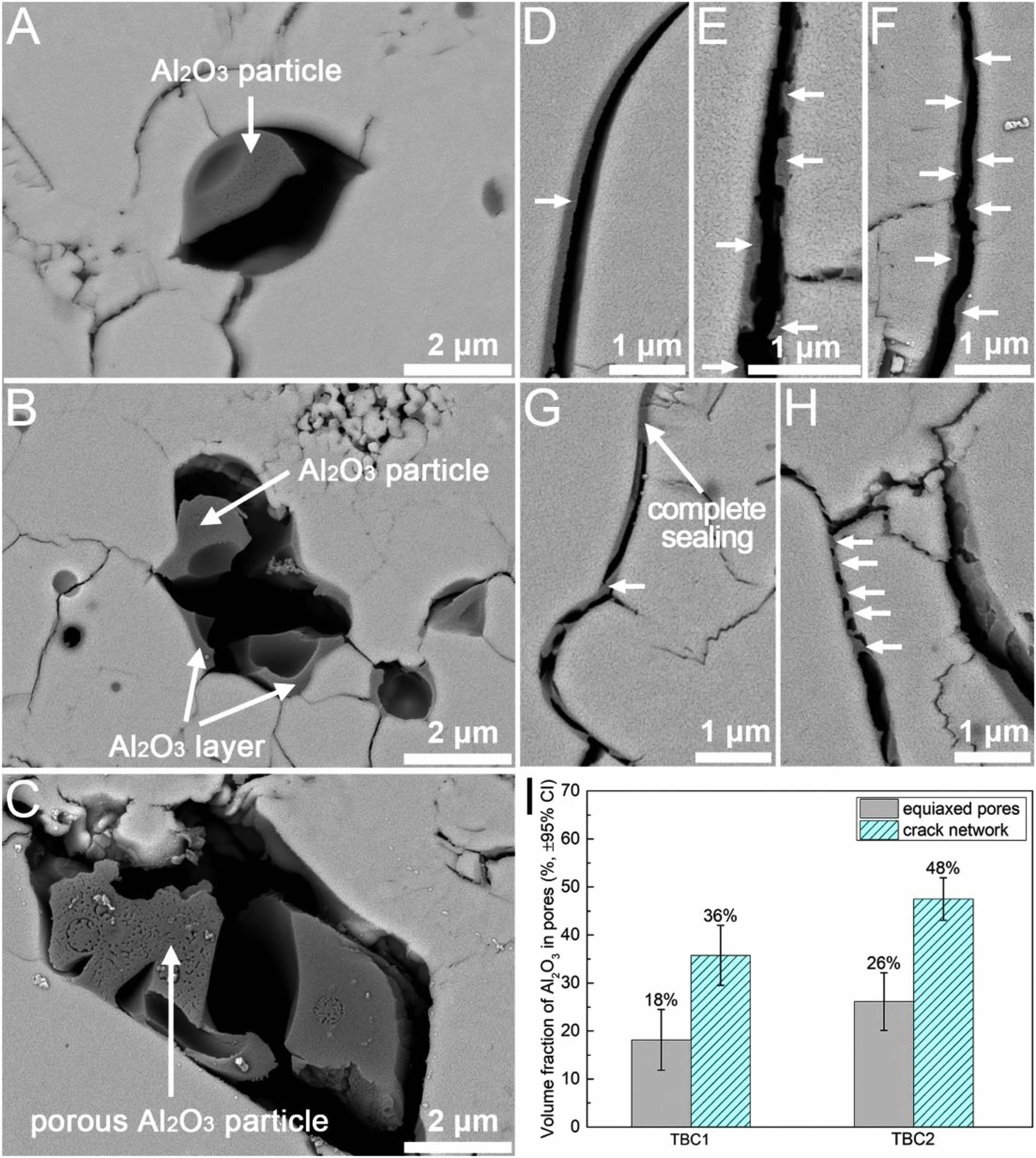
In the high-temperature environment, CMAS will transform into a molten state and deposit in the micropores inside the coating. The stiffness of the CMAS-infiltrated TBC will increase when CMAS solidifies, making the coating less strain tolerant and thus more easy to fail by spallation [81]. Pore design can optimize corrosion resistance of TBCs from two aspects: 1) Reducing the accumulated CMAS content in the coating and 2) reducing the contact area between CMAS and the ceramic layer. Shan et al. [82] used Al2O3-sol to modify the microscopic pores and microcracks inside the APS-TBC, and the internal microscopic morphology of the modified coating was shown in Fig. 6. The introduced Al2O3-sol can optimize the corrosion resistance of the thermal barrier coating from two aspects. Firstly, the Al2O3-sol effectively reduced the width of pores and microcracks, increased the curvature of pores, and even directly blocked the pores, thus reducing the penetration depth of CMAS in the TBCs. Secondly, Al2O3 would react with CMAS to form elongated anorthite crystals, thereby reducing the reaction between the molten and the ceramic layer. Therefore, adjusting the pore structure of TBC by Al2O3-sol impregnation is an effective method to reduce CMAS damage.
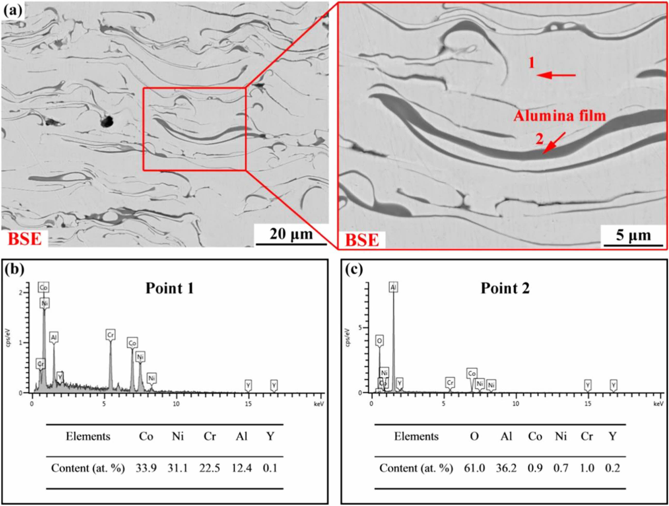
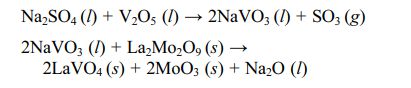
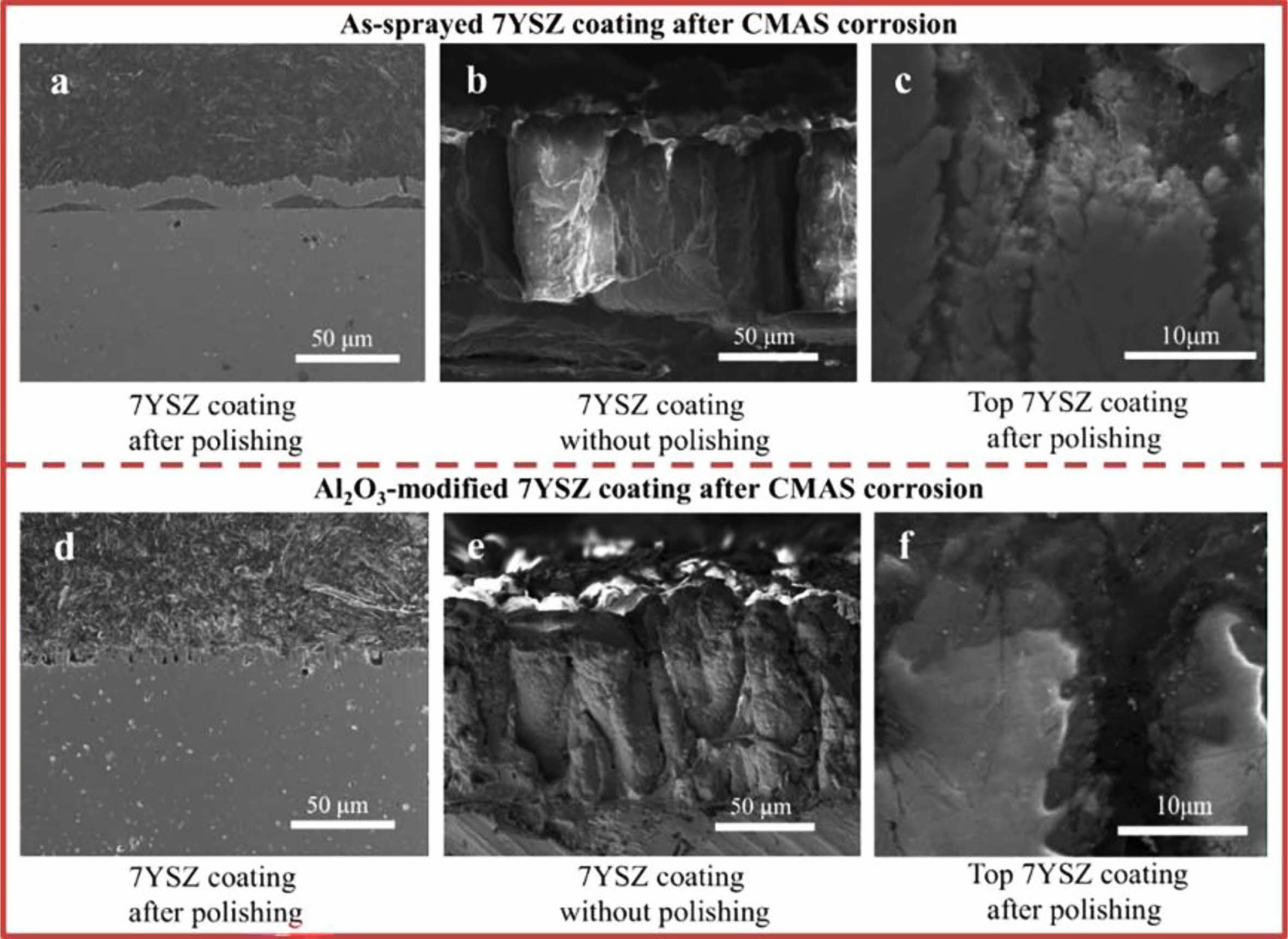
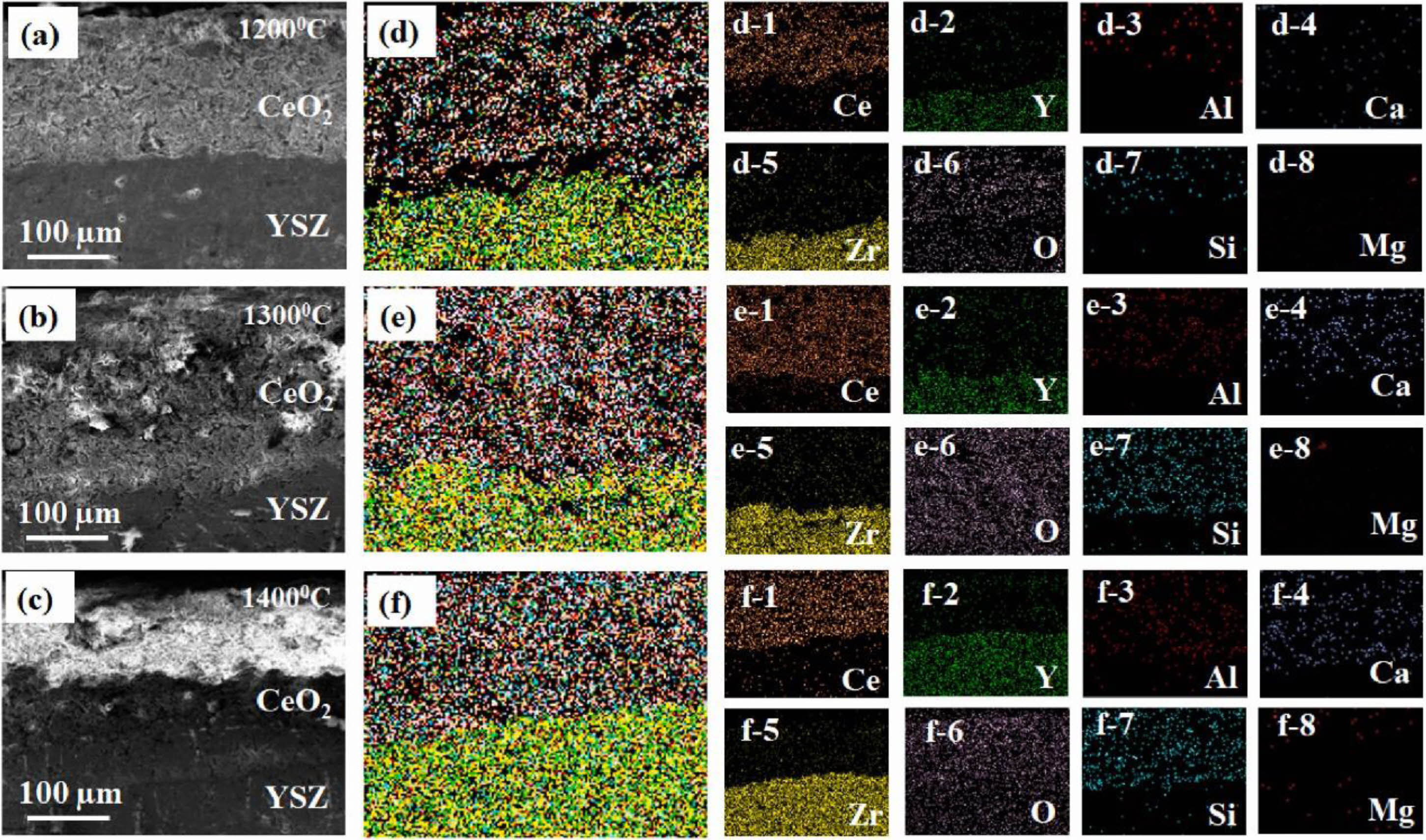
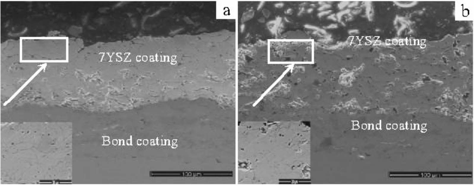
The surface protective layer is a dense and porous coating, which can protect the thermal barrier coating from both physical and chemical aspects in a high-temperature environment [63]. In the physical aspect, the surface protection layer prevents CMAS penetration or reduces CMAS content attached to the coating surface; In the chemical aspect, the surface protection layer can react with the sediments on the coating surface, forming a denser surface while digesting the sediments and slowing the penetration of corrosion [83]. Zhang et al. [84] deposited Al2O3 film on the surface of 7YSZ coating by magnetron sputtering and vacuum heat treatment. The Al2O3 film was dense without cracks and pores, which could effectively prevent the penetration of CMAS at 1200 °C. In addition, CaAl2Si2O8 and MgAl2O4 formed by the reaction of Al2O3 and CMAS could further seal the cracks and pores inside the coating and inhibited CMAS penetration. The test results were shown in Fig. 7. After CMAS corrosion, buckling and spallation were observed in the as-prepared 7YSZ TBCs. However, no cracks appeared in the Al2O3-modified 7YSZ-TBCs. Islam et al. [85] prepared a CeO2 overlay on the surface of 7YSZ-TBCs by APS. Among all the rare earth oxides, CeO2 is an impressive material for corrosion resistance due to its peculiar electronic structure, which intimates an attractive electron transfer property. In the Na2SO4+V2O5 corrosion environment, the CeVO4 formed by the reaction of CeO2 and NaVO3 could effectively fill the pores inside the coating and prevent the penetration of corrosive salts. In the CMAS corrosion environment, as shown in Fig. 8, according to the dissolution/reprecipitation mechanism, CeO2 was diffused into molten CMAS and formed CeAlSiO precipitates [86]. CeAlSiO as the sealant could effectively fill the pores in the CeO2 overlay and prevent CMAS from penetrating into TBCs. Soltani et al. [87] prepared a CSZ+Al2O3+MoSi2 self-healing protective layer on the surface of a CSZ coating using APS. MoSi2 in the coating would be oxidized at a high temperature and reacted with ZrO2 to form ZrSiO4. The specific reaction process was as follows:

Mo5Si3, SiO2, and ZrSiO4 generated by the reaction could fill and seal the pre-existing pores and cracks in the TBCs, preventing the penetration of molten salt into the coatings. In addition, CeO2 in the form of a free state in the protective layer reacted with NaVO3 to form cubic CeVO4 crystals, which further filled the cracks and pores inside the coating. Dharuman et al. [88] prepared a La2Mo2O9 corrosion protection layer on the surface of YSZ coating. They analyzed the protection mechanism of the La2Mo2O9 layer on YSZ. In the environment of Na2SO4+V2O5, La2Mo2O9 reacted with NaVO3 to form LaVO4 and MoO3. The specific reaction process was as follows:
La2Mo2O9 could effectively consume the corrosion products deposited on the surface of the coating, and LaVO4 in the shape of rice grains could effectively fill the cracks and pores between the splats and slow down the penetration of NaVO3.
The surface treatment of the coating can modify the surface morphology of the TBCs and reduce the penetration of the deposit into the coatings by closing the micro-cracks and pores on the surface of the coatings. At present, the surface treatment technology for TBCs is mainly laser surface modification.
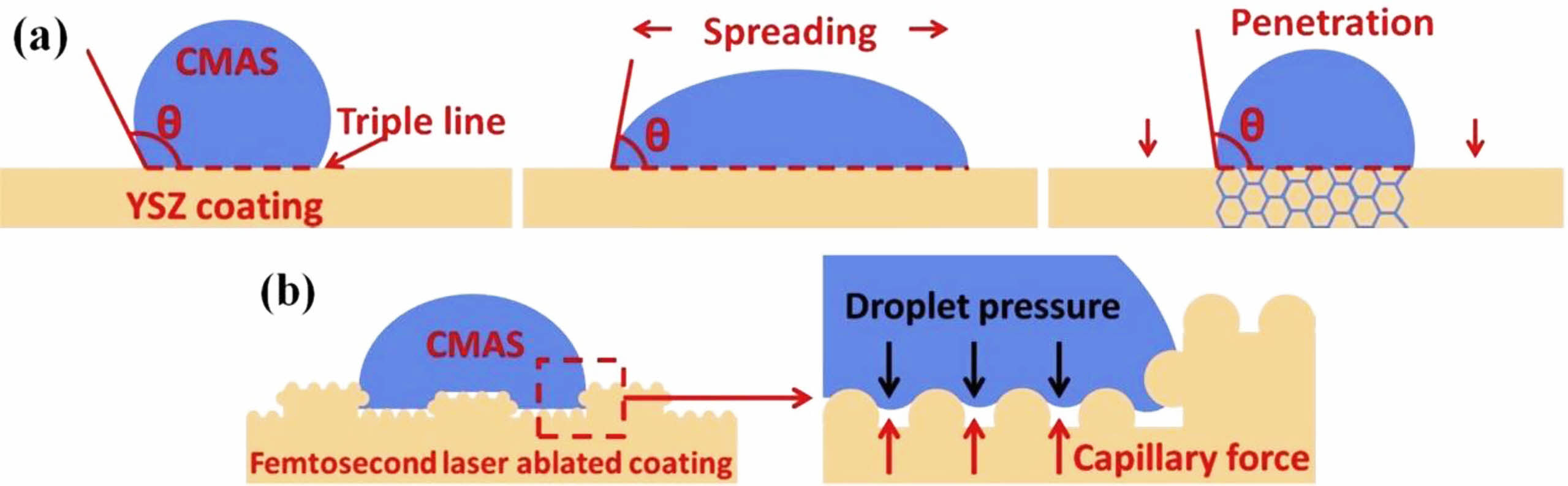
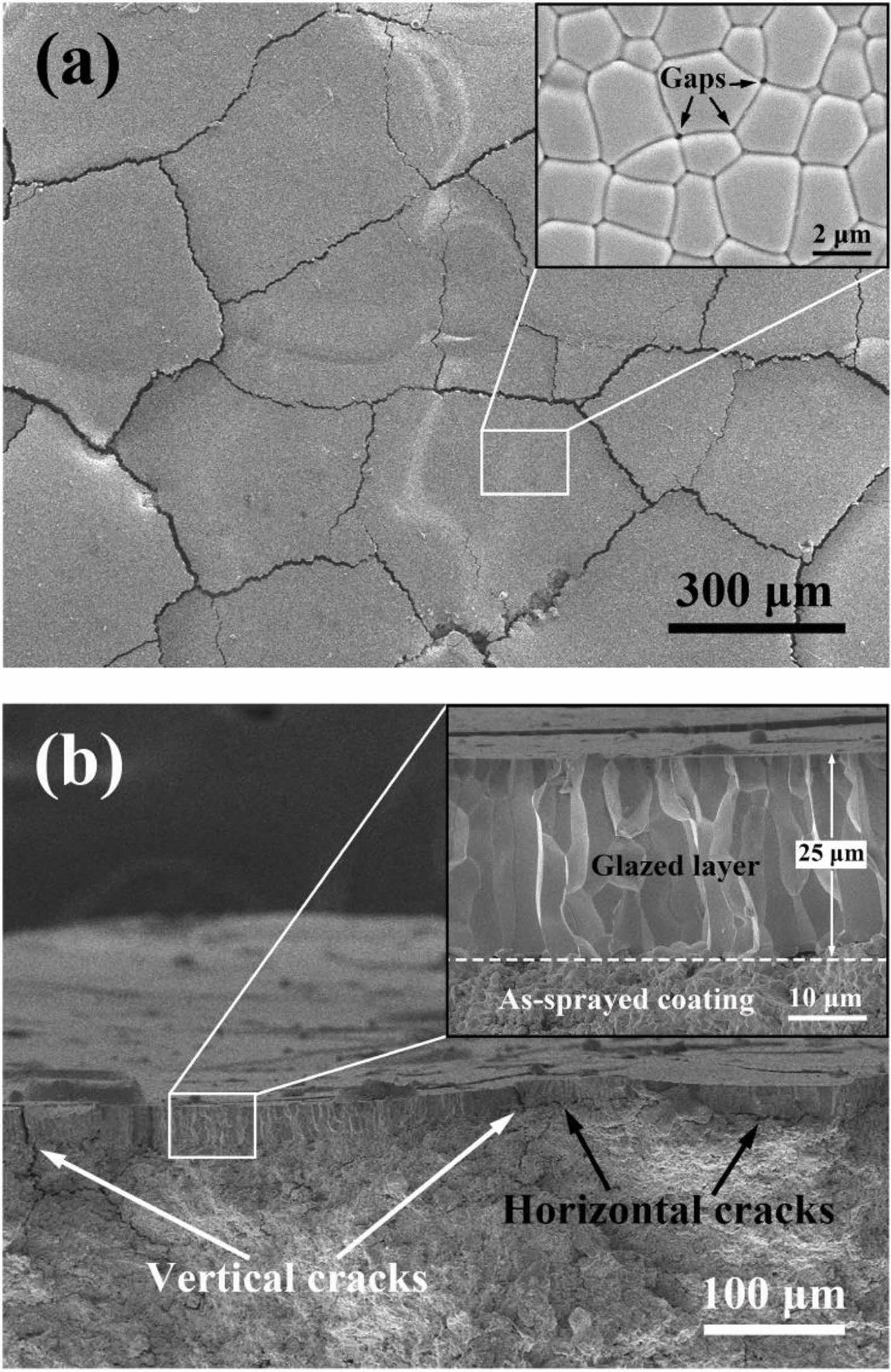
Laser surface treatment technology is to scan the surface of TBCs with a laser beam with a high power density. High power laser rapidly melts the surface of the ceramic layer, then rapidly cools and solidifies, closing the microcracks and pores on the coating surface during solidification. In addition, laser surface treatment limits the deposition of corrosives on the coating surface by changing the coating surface morphology and the wettability between the coating surface and the molten salt [26]. Kang et al. [89] used a femtosecond laser to ablate the surface of the YSZ coating. As shown in Fig. 9, the square grooves formed on the surface of the coating after ablation changed the wettability of CMAS and the surface of the TBCs, limiting the deposition of CMAS on the surface of coatings. Yan et al. [90] used a laser to adjust the surface microstructure of the YSZ coating. The morphology of the modified coating was shown in Fig. 10, and a segmented dense columnar remelted layer was formed on the surface of the coating. In a CMAS corrosion environment, the remelted layer could keep the columnar structure for a long time and not react with CMAS to form a precipitate. However, due to the high fluidity of CMAS at high temperatures, the gap between the columns became a diffusion channel for CMAS, causing CMAS to damage the YSZ coating below the remelted layer. Yi et al. [91] used a continuous diode laser to treat the surface of YSZ coating and analyzed the influence of laser power on the surface morphology of the coating. The surface and cross-sectional morphology of laser-modified TBCs were shown in Fig. 11. By increasing the laser power and scanning rate from the case of low-power laser to high-power laser, wider segmented cracks appeared, which could be attributed to the higher thermal tensile stresses that occurred in the case of high-power laser and could not be released easily during the rapid cooling stage in the local volume. In the Na2SO4+V2O5 environment, the top dense remelted layer could effectively prevent the penetration of V into the coating, but the existence of segmented vertical cracks became the only path for the molten salt penetration. To slow down the diffusion of corrosive in the vertical cracks inside the remelted layer, Guo et al. [81] proposed a double-layer laser layer design to reduce the penetration of corrosive by designing vertical cracks as segmented structures. Guo et al. [92] used Nd: YAG laser to prepare a double-layer laser glaze on the surface of YSZ coating. Compared with the single laser glaze layer, the vertical cracks inside the double laser glaze layer exist in the form of bifurcation and staggered. Under molten CMAS conditions, the coating with double laser-glazed layers highly resists to melt penetration, and the glazed layer exhibits excellent phase stability and structural integrity.
Coating Material Design
Yttrium oxide partially stabilized zirconia (YSZ) has become the most widely used TBCs ceramic material due to its low thermal conductivity, significant thermal expansion coefficient, and excellent fracture toughness [93]. However, in a hot corrosion environment, Y2O3 reacts with the corrosive, resulting in a phase change in the ZrO2 and ultimately the failure of the TBCs [94]. To enable TBCs to serve in complex environments, researchers have begun to develop ceramic materials with superior corrosion resistance. New corrosion-resistant TBCs materials mainly include multi-rare earth oxide doped ZrO2, rare earth zirconate, and rare earth phosphate.
Multi-rare earth oxide ceramic materials refer to the corrosion resistance of ceramic materials optimized by various rare earth oxides. In Na2SO4 and V2O5 corrosion environments, rare earth oxides with a strong Lewis basicity will first react with the molten salt. In contrast, rare earth oxides with weaker basicity can still be retained, and the ZrO2 is stabilized to the t phase to avoid coating shedding caused by the ZrO2 phase transition [95]. Song et al. [96] prepared Y2O3-Gd2O3-Y2O3 doped ZrO2 TBCs and analyzed the corrosion behavior of the coatings with Na2SO4+V2O5. Since Gd2O3 had the largest ionic radius, it had the strongest alkalinity and would be the first to react with NaVO3; In contrast, Yb2O3 had the smallest ionic radius and the lowest alkalinity and would remain in the coating until the final corrosion stage and stabilize the ceramic layer to t-ZrO2. In the CMAS corrosion environment, the corrosion resistance of rare earth oxides is judged by optical alkalinity. Optical basicity essentially refers to the ability of electron transfer. When rare earth elements have strong optical alkalinity, they will preferentially dissolve into CMAS and form precipitation [97]. Fan et al. [98] prepared Sc2O3-Y2O3 co-stabilized ZrO2 TBCs and analyzed the CMAS corrosion behavior. The results showed that Y2O3 with large optical basicity (OB=1.00) would dissolve into CMAS and form precipitates during the corrosion process, while Sc2O3 with small optical basicity (OB=0.89) remained in the coating and stabilized ZrO2 into the t phase. Fang et al. [99] doped Yb2O3 with optical basicity of 0.94 in YSZ and analyzed the CMAS corrosion behavior of Yb-Y2O3-ZrO2 TBCs. The results showed that Y2O3 with high optical basicity would dissolve in CMAS and form a dense reaction layer at the top to prevent the penetration of CMAS; The solubility of Yb2O3 in CMAS is negligible, so Yb2O3 could be retained in the coating to stabilize ZrO2 and improve the corrosion resistance of the coatings.
The rare earth zirconate chemical formula is M2Zr2O7, which has two crystal structures. When M is a light rare earth element such as La and Nd, it is a pyrochlore structure (Pyrochlore, P); when M is Tb, Dy, and other heavy rare earth elements, it is a defective fluorite structure (Fluorite, F) [100, 101]. Rare earth zirconate has good high-temperature phase stability, high melting point, and excellent corrosion resistance, and it is the most promising material in TBCs. Lanthanum zirconate (La2Zr2O7, LZO) and gadolinium zirconate (Gd2Zr2O7, GZO) are the most widely used rare earth zirconate TBCs materials. Both materials have good sintering resistance and high-temperature phase stability. Yugeswaran et al. [102] analyzed the hot corrosion behavior of APS-LZO coatings against Na2SO4+V2O5. The cross-sectional microstructure of LZO coating after hot corrosion of Na2SO4+V2O5 was shown in Fig. 12. The coating reacted rapidly with the corrosive, and the formed LaVO4 effectively filled the cracks and pores in the coating. The dense reaction layer effectively inhibits the continuous penetration of the Na2SO4+V2O5, indicating that La2Zr2O7 has good corrosion resistance. Ozgurluk et al. [103] analyzed the corrosion behavior of CMAS with LZO, forming substances such as La-apatite, gehlenite, baghdadite, and Ca2Al2Si2O8 in the coating. Krämer et al. [104] found that the reaction process between Gd2Zr2O7 and CMAS was very rapid, could quickly form an apatite phase within tens of seconds, and closed the cracks and pores inside the ceramic layer, prevented the penetration of CMAS into the interior of the coating. Although the two materials have excellent high-temperature corrosion resistance, the rare earth zirconate has a low thermal expansion coefficient and poor fracture toughness. Therefore, the coating is prone to fall off during the cooling process, failing the thermal barrier coating. Thus, optimizing the mechanical properties of rare earth zirconate has become the focus of its application in corrosion-resistant environments. Lyu et al. [105] mixed YSZ with LZO to optimize the mechanical properties of the TBCs. The cross-sectional morphology of the composite coating after corrosion for 10 h and 20 h in a CMAS environment were shown in Fig. 13. A dense corrosion layer was formed at the top of the coating, and the thickness of the corrosion layer increased with the extension of the holding time. The corrosion layer was dense without cracks, indicating that YSZ could effectively optimize the mechanical properties of the LZO coating and avoid the formation of cracks in the top corrosion layer during cooling. Cai et al. [106] prepared La2Zr2O7-SrZrO3 TBCs by APS and analyzed the CMAS corrosion resistance of the coatings. The experimental results showed that La2Zr2O7-SrZrO3 composite TBC has better corrosion resistance than 8YSZ coating. During the corrosion process, a dense reaction layer was formed between CMAS and TBCs, mainly composed of Ca2La8(SiO4)6O2 and c-ZrO2. The results showed that the composite coating could effectively prevent CMAS penetration, and SrZrO3 could optimize the fracture toughness of LZO and avoid cracks in the coating during cooling.
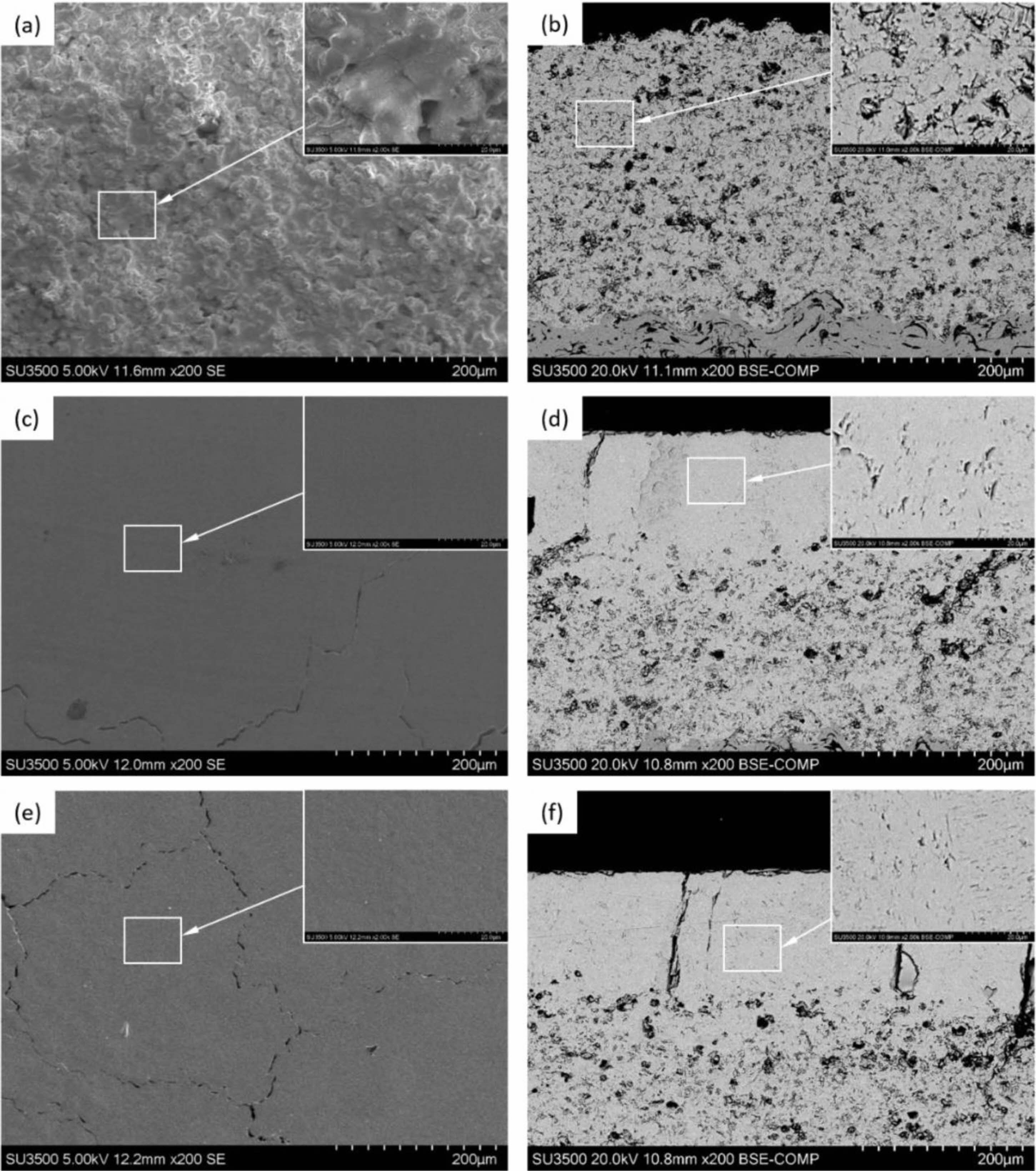
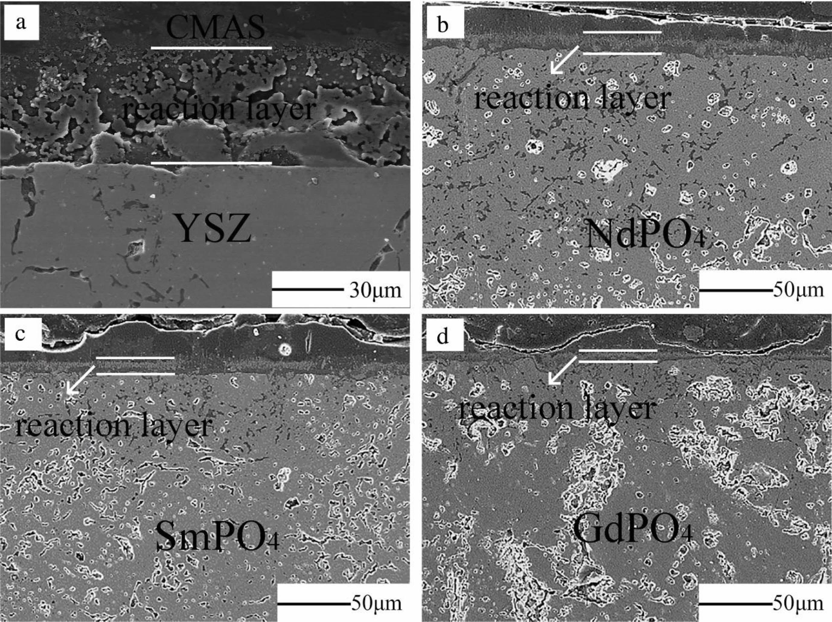
Rare earth phosphate (MPO4) has two structures depending on the ionic radius of the rare earth element. When M is No. 57-64 rare earth elements, the rare earth cation has a larger radius, and the rare earth phosphate has a monazite structure; when M is No. 65-71 rare earth elements, the rare earth cation radius is small, and the rare earth phosphate is the structure of xenotime. The rare earth phosphate with xenotime structure has high thermal conductivity and low thermal expansion coefficient, which is unsuitable for the top layer material of thermal barrier coating. The material with a monazite structure is considered an excellent top layer material for thermal barrier coatings due to its significant thermal expansion coefficient and low thermal conductivity. Lanthanum phosphate (LaPO4) with a monazite structure is a widely studied and applied material in rare earth phosphates. It has a high melting point (2070 ℃), low thermal conductivity, excellent high-temperature phase stability, and good high-temperature sulfur and vanadium corrosion resistance [107]. Therefore, LaPO4 is used as the top layer material in TBCs. Zhang et al. [108] analyzed the corrosion mechanism of LaPO4 and V2O5 at different temperatures. When the ambient temperature was 700-900 ℃, the corrosion product was La(P,V)O4. Since the formation of La(P,V)O4 did not affect the internal microstructure of the coating, the TBCs could still be used commonly, indicating that LaPO4 had excellent corrosion resistance at this temperature; When the ambient temperature was 1000 °C, the corrosion products contained a small amount of LaVO4. The rice-shaped LaVO4 filled the voids in the coating, prevented further penetration of V2O5, and effectively protected the internal structure of the coating. Guo et al. [109] analyzed the CMAS corrosion resistance of LaPO4 at 1250- 1350 ℃. At 1250 ℃, LaPO4 reacted with CMAS to form CaAl2Si2O8 and Ca2+x(La,Al)8-x(PO4)X(SiO4)6-xO2 precipitates. The formation of apatite and square crystals formed an effective seal on the surface of the coating, preventing continuous penetration of the molten CMAS. However, at 1300 and 1350 ℃, the viscosity of CMAS was low, which made the penetration rate of CMAS in the coating more significant than the rate of reaction with LaPO4. Therefore, it was difficult to form crystalline products in the coating to prevent continuous CMAS infiltration. Wang et al. [110] prepared NdPO4, SmPO4, and GdPO4 rare earth phosphate TBCs by APS and compared the CMAS corrosion behavior with conventional YSZ at 1250 ℃. The cross-sectional morphology of the coating after CMAS corrosion was shown in Fig. 14. A loose reaction layer of ~50 μm was formed on the surface of the YSZ coating, while a dense and crack-free reaction layer of ~15 μm was formed on the surface of three rare earth phosphate thermal barrier coatings. The reaction layer was mainly composed of apatite, anorthite, and spinel crystals, which effectively inhibit the penetration of CMAS. The above studies show that rare earth phosphate is a new type of TBCs ceramic material with excellent corrosion resistance.
|
Fig. 6 (A-H) Cross-sectional BSE images showing the microstructure of the pore-tailored APS TBC (TBC1). The phases pointed by arrows are Al2O3. (I) Volume fractions of Al2O3 in the different types of pores in the pore-tailored APS TBCs. Error bars represent the 95% confidence intervals (95% CI) [82]. |
|
Fig. 7 As-sprayed and Al2O3-modified PS-PVD 7YSZ TBCs after CMAS corrosion. (a-c) As-sprayed TBCs after CMAS corrosion (a: assprayed TBCs showing buckling between 7YSZ coating and substrate, b: cross-sectional microstructure without polishing, and c magnified image showing spallation). (d-f) Al2O3-modified TBCs after CMAS corrosion (d: cross-sectional microstructure, e: cross-sectional microstructure without polishing, and f magnified image showing no apparent spallation) [84]. |
|
Fig. 8 a-c) showing cross-sectional FESEM images of the hot corroded CYSZ coating, (d-f) secondary electron mapping of Ce, Zr, Y, Ca, Al, Mg, Si, and O elements through the YSZ coatings at different temperatures (1200-1400 ℃) and (d-1)-(f-8) shows the individual distribution of Ce, Zr, Y, Ca, Mg, Al, Si, and O [85]. |
|
Fig. 9 (a) Schematic diagram of contact angle decreasing process; (b) Schematic representation of CMAS droplet on femtosecond laser ablated coating [89]. |
|
Fig. 10 Surface (a) and fracture cross-section (b) of the laserglazed coating [90]. |
|
Fig. 11 SEM micrographs of the (a) top surface and (b) cross section of the as-sprayed coating, (c) top surface and (d) cross section of the retreated coating in the case of LR-low, and (e) top surface and (f) cross section of the retreated coating in the case of LR-high [91]. |
|
Fig. 12 Cross-sectional micrograph of Na2SO4+V2O5 mixture reacted La2Zr2O7 coating zone heat treated at 1350 K for 5 h [102]. |
|
Fig. 13 Results of CMAS corrosion tests for the LZ-YSZ coating: (a) cross-sectional microstructure after 10 h, (b) cross-sectional microstructure after 20 h, and (c) Raman spectra after 20 h. Each number indicates the overall and highly magnified microstructures and the EDS mapping result. The thicknesses of both the upper and lower areas are 150 μm [105]. |
|
Fig. 14 Cross-section SEM images of the CMAS attacked bulks. (a) YSZ, (b) NdPO4, (c) SmPO4, (d) GdPO4 [109]. |
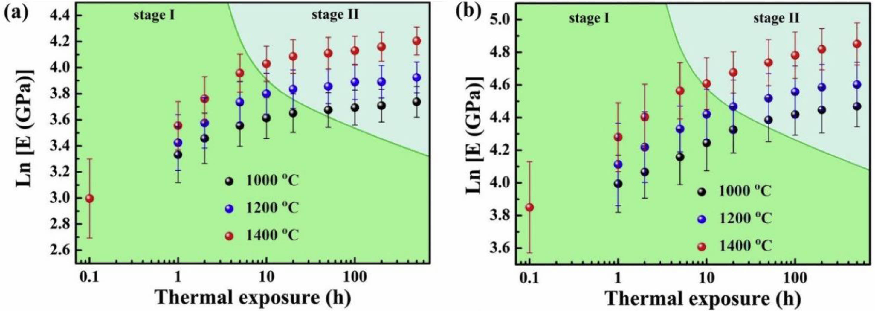
Performance degradation caused by ceramic layer sintering is the main problem of TBCs' durability degradation when TBCs work in a high-temperature environment. And with the increase in the working temperature of the TBCs, the degree of sintering and densification of the coating will increase [111]. During thermal spraying, the ceramic powder located outside the plasma flame is fully melted and deposited on the surface of the bond coat. Due to the molten ceramic's ultra-fast cooling on the bond coat's surface, a large amount of stress is accumulated inside the splats, resulting in many microcracks inside the splats [112]. The ceramic powder located inside the plasma flame is deposited in a partially melted or unmelted state due to insufficient heat heating. The microscopic pores in unmelted and partially melted powders can provide space for phonon scattering and optimize the thermal insulation performance of TBCs [113]. Microcracks between the splats can offer a large amount of strain space for the coating and reduce the internal stress of the coating during thermal cycling. When the TBCs are kept at a high temperature for a long time, the diffusion rate of atoms around the microcracks and pores will increase, which will heal the pores and cracks inside the coating, resulting in a significant increase in the thermal conductivity and elastic modulus of the coating [63]. Tsipas et al. [114] analyzed the sintering behavior of plasma sprayed YSZ TBCs at 1350 ℃. When the holding time was 100 h, 1.4% shrinkage occurred inside the coating, and the overall in-plane stiffness of the coating increased from 10±5 GPa to 60±10 GPa. Li et al. [115] and Thompson et al. [116] analyzed the relationship between Young's modulus of coating and the sintering process. As shown in Fig. 15, due to the thermodynamic properties of the coating being very sensitive to sintering time and temperature, in the initial stage of sintering coating, internal microcracks and pores healed rapidly, and Young's modulus quickly increased; when the sintering reached the second stage, the sintering driving force of the coating decreased due to the disappearance of micropores, so the increase rate of Young's modulus decreased. Currently, researchers optimized the coating structure and ceramic powder structure to improve the sintering resistance of thermal barrier coatings at high temperatures.
Coating structure design
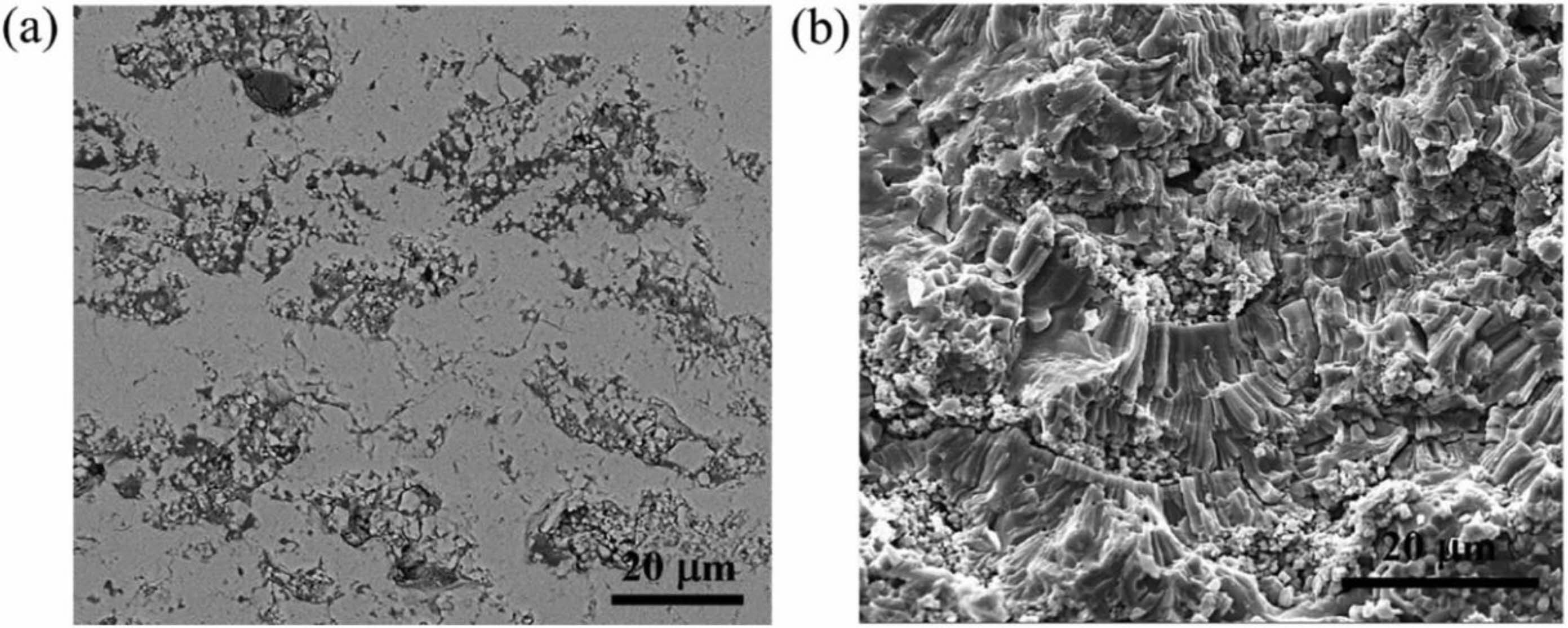
In terms of TBCs structure, bimodal microstructure TBCs have been proven to optimize the sintering resistance of coatings effectively. The bimodal structure refers to embedding porous powder particles into the coating during plasma spraying so that a large quantity of nano-pore areas are retained in the prepared coating. Microcracks and pores in the nano-pore areas can effectively improve the fracture toughness of the coating, release internal stress, and resist crack propagation [117]. In addition, at high temperatures, microscopic pores can effectively counteract the sintering inside the coating, allowing the coating to maintain good thermo- dynamic properties for a long holding time [118]. Huang et al. [119] fabricated YSZ TBCs with a bimodal structure by designing a plasma spray gun. The cross-sectional morphology of the bimodal coating was shown in Fig. 16. Compared with the traditional YSZ TBCs, there were uniformly dispersed unmelted micro-agglomerated YSZ powder particles inside the bimodal coating. In the high-temperature environment, the rapid sintering inside the nano-region would form coarse pores inside the coating so that the porosity inside the coating remains relatively constant, avoiding the rapid increase of the elastic modulus of the coating during the sintering process so that the coating can have excellent heat insulation performance and strain compliance for a long time. Huang et al. [120] analyzed the effect of nanoparticle size on the sintering behavior of bimodal coatings. As shown in Fig. 17 and 18, many pores and microcracks in the traditional YSZ coating healed during sintering, and the porosity decreased to 5%. The bimodal structure coating could maintain a high porosity. The micropores would form coarse pores near the nano-zone during the healing process to compensate for the loss of porosity. Due to the large nano-area pores formed by coarse nanoparticles, the sintering driving force inside the coating during the sintering process is low, so the porosity reduction rate is slow; the pore size of the nano-region formed by fine nanoparticles is small, so it has a faster pore shrinkage rate in the initial stage of sintering. Zhou et al. [121] used the finite element method to compare the stress distribution of bimodal structure YSZ and traditional YSZ TBCs. The stress of the bimodal structure YSZ coating in the axial and radial directions was 67% and 73% of the traditional YSZ, respectively. The excellent sintering resistance, low internal stress, and excellent thermodynamic properties of bimodal structure thermal barrier coatings make them widely used in high-temperature environ- ments.
Structure Design of Ceramic Powder
The internal microstructure and performance of the thermal barrier coating are not only related to the preparation method of the coating but also to the morphology of the ceramic powder [122, 123]. Therefore, optimizing the structure of ceramic powders is the basis for improving coating performance.
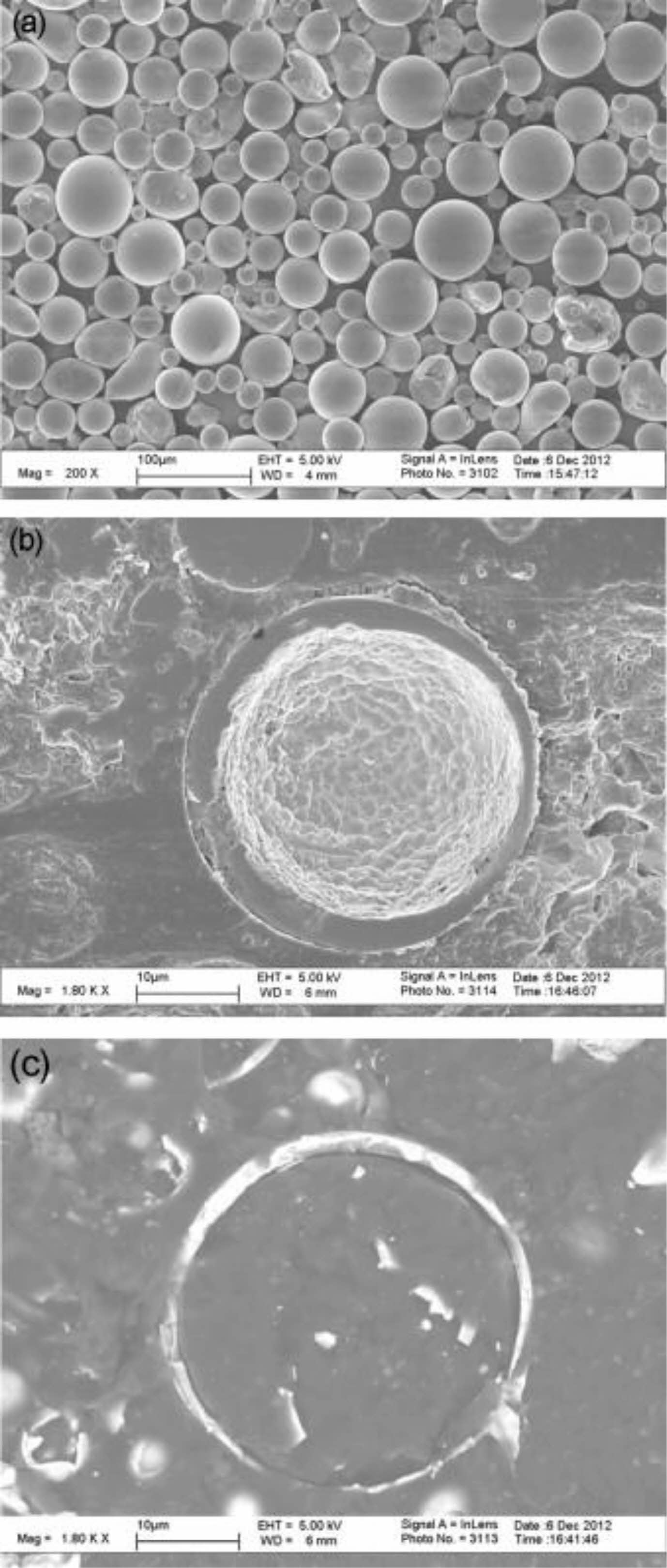
Oerlikon Metco successfully designed and developed YSZ hollow spherical powder (HOSP) for high-performance thermal spraying in the 1990s. The HOSP preparation methods mainly include the spray drying method, plasma spheroidization method, and template method, in which the plasma spheroidization method is widely used because of its simple process, low cost, and controllable particle size [124-126]. Fig. 19 is the SEM photo of YSZ hollow spherical powder prepared by plasma spheroidization [125]. It can be seen from Fig. 19 that a ceramic shell wrapping forms the powder. The powder's unique structure is because, in the plasma jet, the molten powder forms hollow spherical droplets under external gas and surface tension, which rapidly solidify to form YSZ HOSP. The powder has a smooth surface, high strength, and good flowability so that it can be produced in large quantities and used for plasma spraying. Zhang et al. [127] compared the microstructure of atmospheric plasma sprayed HOSP YSZ-TBCs with traditional YSZ-TBCs and analyzed the internal porosity of the coating by industrial CT. Fig. 20 showed that the internal porosity of HOSP YSZ TBCs was 19%, which was much higher than 11% of traditional YSZ TBCs. The high porosity inside the coating not only provides space for phonon scattering and reduces the thermal conductivity of the coating but also provides stress release space and optimizes the thermal cycle life of the coating. Ercan et al. [128] compared the sintering resistance of agglomerated YSZ TBCs and HOSP YSZ TBCs. Before heat treatment, the two coatings had the same porosity and thermal conductivity. After holding at 1200 °C for 50 h, the thermal conductivity of HOSP YSZ coating was much lower than that of agglomerated YSZ coating, indicating that HOSP YSZ coating had excellent sintering resistance at high temperatures.
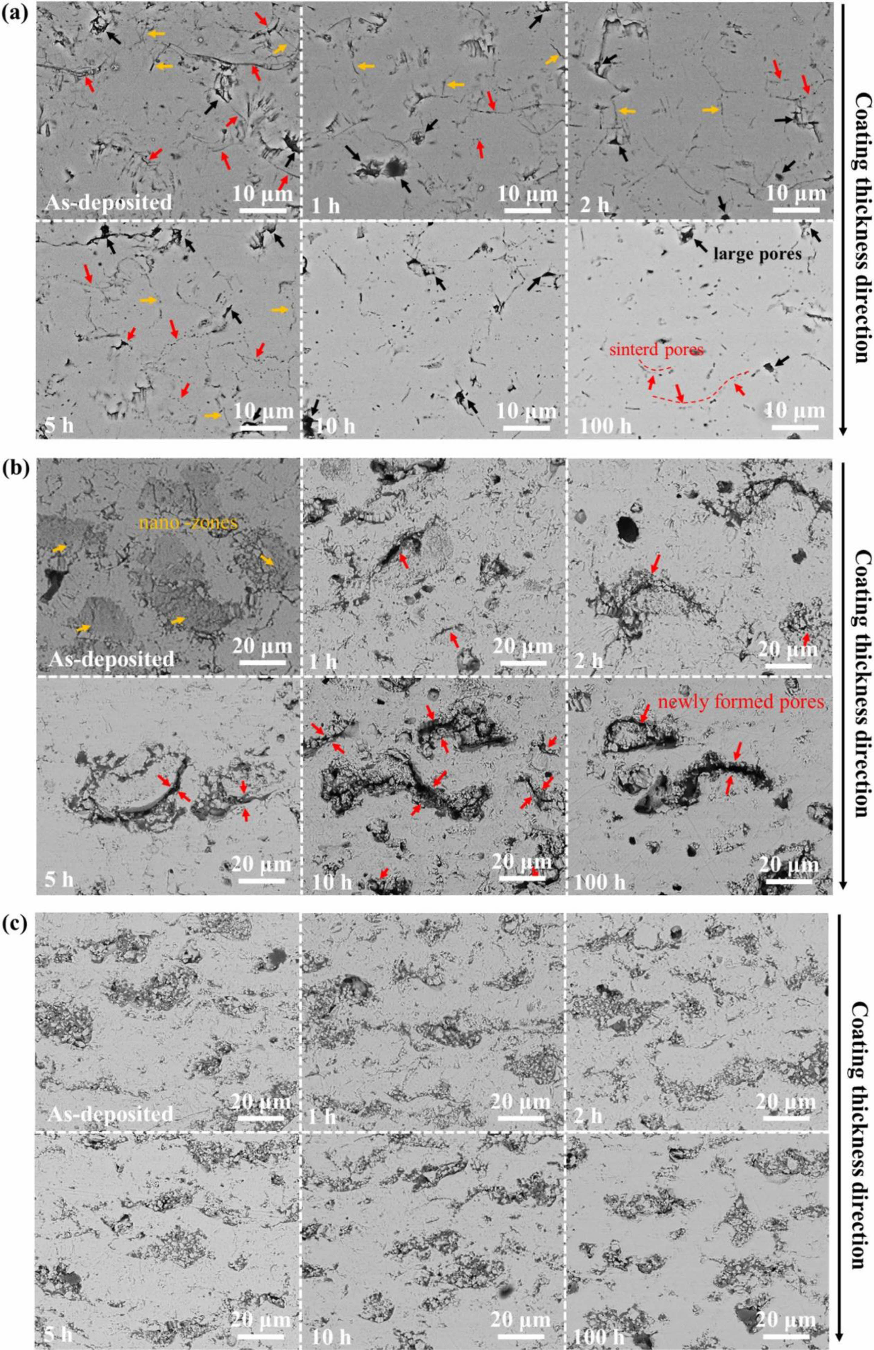
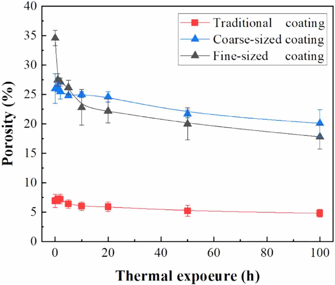
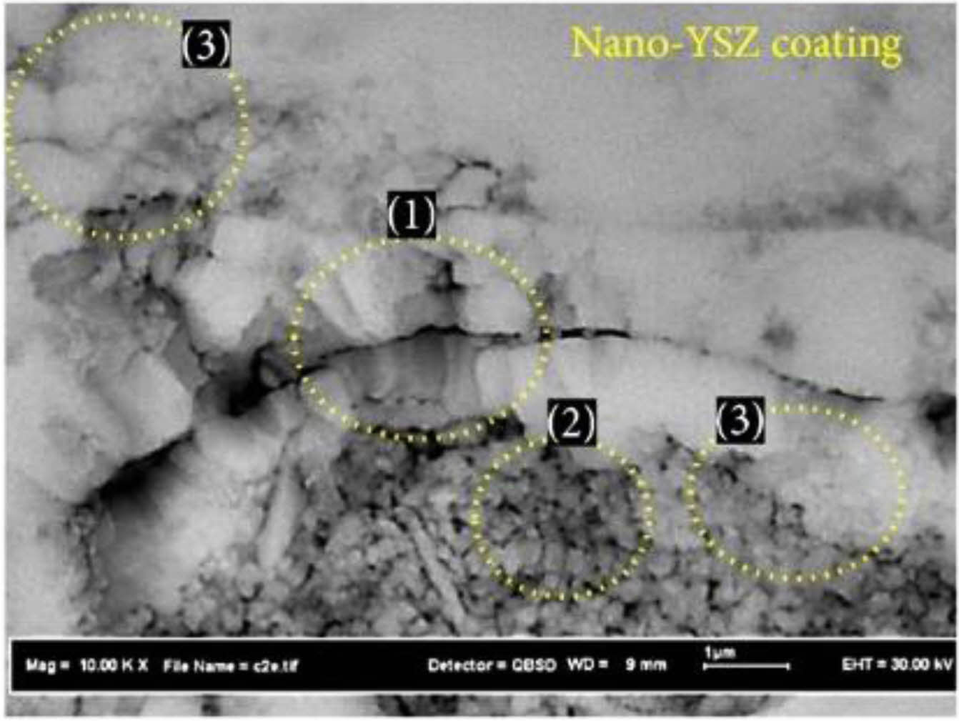
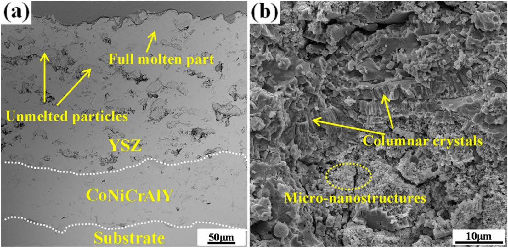
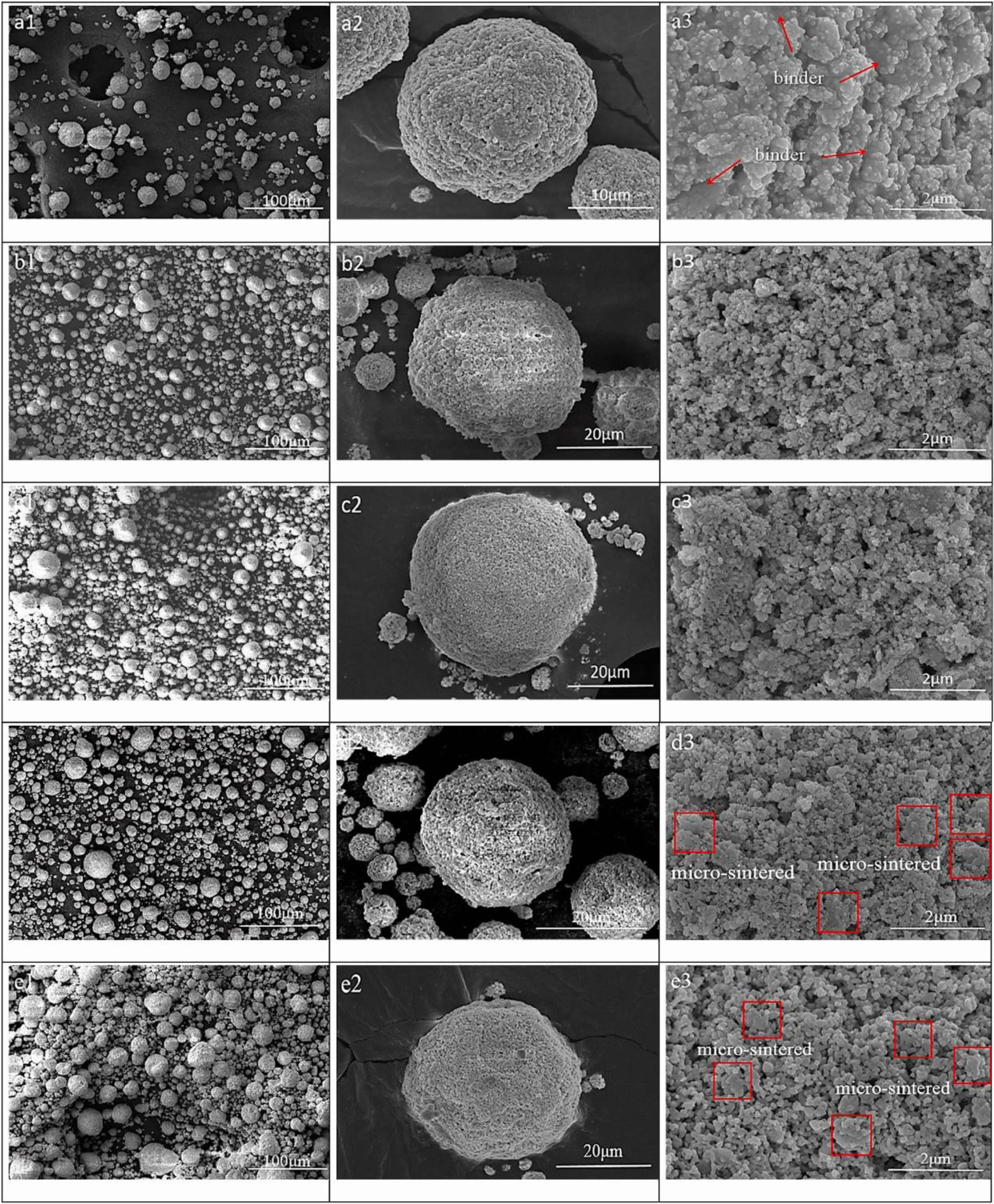
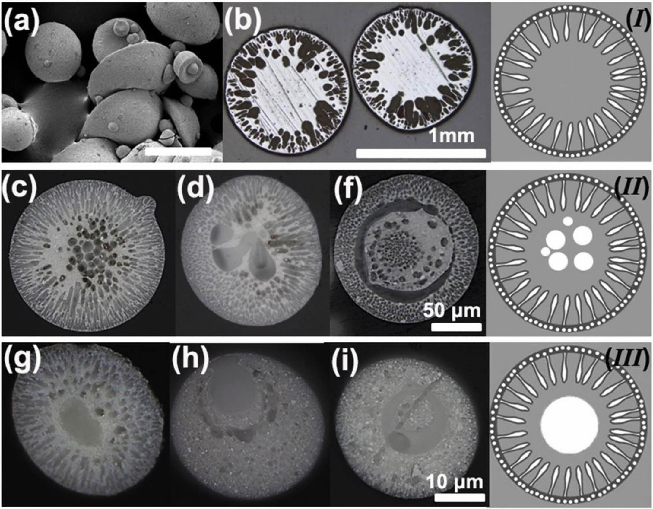
With the development of nano-materials, the research on nano-ceramic materials applied to the new generation of TBCs has gradually emerged. Nano-ceramic materials have good plasticity, material strength, and fracture toughness. Lima et al. [129] found that nanostructured YSZ TBCs still have low fracture toughness after exposure at 1400 ℃ for 20 h, and there was still a large porosity inside the coating. Daroonparvar et al. [130] analyzed the internal structure and isothermal oxidation properties of nano-YSZ TBCs. As shown in Fig. 21, the nano-YSZ coating contains a large amount of nano-sized pores and columnar crystals, which can effectively prevent oxygen penetration and slow down the growth rate of TGO at high temperatures. Chen et al. [131] analyzed the bonding strength of nano-YSZ TBCs. Since the plasma flame could fully melt the nanoparticles during the spraying process, good mechanical interlocking could be maintained between the splats, resulting in average bonding strength of 45 MPa. Although nano-YSZ powder has relatively excellent thermodynamic properties, it cannot be directly applied to thermal spraying due to its lightweight and poor fluidity. Therefore, researchers began to develop new coating preparation methods to prepare nano-YSZ TBCs with excellent sintering resistance. Suspension plasma spraying (SPS) is to disperse ceramic powders in a specific suspension and inject the suspension into a plasma flame through a particular feeding system to form a coating [132]. Since SPS transports powders by liquid, the powder size is required to be on the nanometer scale. Xiao et al. [133] compared the sintering resistance of two YSZ TBCs prepared by SPS and APS. Since the SPS TBCs were segmented structures with vertical cracks, the internal stress of the coating could be released by the shrinkage of the crack in the early stage of sintering. In the later stage of sintering, the shrinkage of the micropores in the coating would enlarge the vertical crack width so that the coating still had a large strain space. Therefore, SPS TBCs had better sintering resistance. In addition to optimizing the spraying method, nanopowder particles can be agglomerated for plasma spraying. Xue et al. [134] synthesized nano-agglomerated YSZ powder by high-temperature hydrothermal and spray drying methods and applied the powder to APS. The cross-sectional morphology of the as-prepared coating was shown in Fig. 22. A large number of nanostructures, columnar crystals, and nanopores were evenly distributed in the coating. Nanopores effectively improve the sintering resistance, strain tolerance, and fracture toughness of the coating, thereby prolonging the service life of the thermal barrier coating. Li et al. [135] analyzed the effect of calcination temperature on agglomerated nano YSZ ceramic powders prepared by plasma spray. As shown in Fig. 23, a small amount of powder sintering appeared in the calcined powder, but there were still a large number of nano-pores on the outer surface, indicating that the nano-ceramic powder prepared by spray drying had excellent sintering resistance. The spray drying method can be a simple and economical method for preparing agglomerated nanopowders and enables the spraying of nanopowders. In addition to using the spray drying method, Guo et al. [136] and Zou et al. [137] proposed agglomerating nano-YSZ ceramic powder by the electro-spray technique (ESP). The microstructure of agglomerated ceramic powders with different particle sizes was shown in Fig. 24. There were many nano-pores on the outer surface of the powder, and a large amount of space was retained inside the powder. The unique powder structure allows for a large porosity inside the as-prepared coating, resulting in a high sintering resistance of the ceramic layer, thus optimizing the thermodynamic properties of the coating. The ESP technology has a lower processing cost than the spray drying method. It can control the morphology and particle size of the agglomerated powder so that ESP can more widely use it in the field of thermal spraying.
|
Fig. 15 Changes of elastic modulus during thermal exposure on double logarithmic plots: (a) macroscale and (b) microscale [114]. |
|
Fig. 16 Typical (a) cross-section microstructure and (b) fracture morphology of the EMAP TBC comprising uniformly dispersed microagglomerated particles in a coating matrix [118]. |
|
Fig. 17 Microstructure evolution behavior of the three kinds of coatings during thermal exposure at 1300 ℃: (a) traditional structure YSZ coatings; (b) fine-sized YSZ coatings and (c) coarse-sized YSZ coatings [119]. |
|
Fig. 18 Porosity evolution behavior of the three kinds of coatings during thermal exposure [119]. |
|
Fig. 19 SEM images of HS: (a) micrograph of HS, (b) secondary electron cross-sectional micrograph, and (c) backscattered electron cross-sectional micrograph [124]. |
|
Fig. 20 Microstructures of TBCs made of AS (a) and HS (b) [126]. |
|
Fig. 21 Cross-section of as-sprayed nano-YSZ coating (with a trimodel structure), (1) columnar grins, (2) semimelted nano powders, and (3) micro- and nanoequiaxed grains [129]. |
|
Fig. 22 Cross-sectional (a) and fracture (b) morphologies of 8YSZ nano-structured TBC [133]. |
|
Fig. 23 SEM morphology of the spray-dried and calcined powders, (a1-a3) powder 1# (spray-dried), (b1-b3) powder 2# (calcined at 500 ℃), (c1-c3) powder 3# (calcined at 700 ℃), (d1-d3) powder 4# (calcined at 900 ℃), (e1-e3) powder 5# (calcined at 1100 ℃) [134]. |
|
Fig. 24 Optical micrographs of polished cross-sections of the sintered ESNP YSZ spheres. (a) The sintered particles with different morphologies and diameters (the scale bar is 2 mm), (b) the millimeter sized spheres with type I microstructure, (c)-(f) the hundreds of micrometers sized spheres with type II microstructure, and (g)-(i) the tens of micrometers sized spheres with type III microstructure [135]. |
TBCs for the surface of hot end components of engines provide excellent and economical thermal insulation. Service life is one of the essential indicators to measure the performance of thermal barrier coatings. The factors affecting the service life of thermal barrier coatings mainly include TGO growth, thermal corrosion, high-temperature sintering, and internal stress of the coating. The different methods used to prolong the service life of thermal barrier coatings are reviewed. This review carries out the future development direction of TBCs from the aspects of metallic bond coat and ceramic layer materials, coating structure, coating preparation method, post-treatment of as-sprayed coatings, and coating detection method.
Due to the gradual increase of the working temperature of the engine and the increasingly harsh working environment, it is necessary to develop ceramic materials with better performance. Currently, the research on rare earth elements doped TBCs ceramic materials mainly focuses on the materials' thermodynamic properties, corrosion resistance, and thermal insulation properties. However, there are few studies on the effects of doping content and doping methods of different rare earth elements on the properties of materials. By revealing the influence of rare earth element doping content and doping method on coating properties, it can provide a theoretical basis for the performance optimization of new ceramic materials. The high-entropy materials currently used in TBCs are mixed in equal proportions of multiple components for high-entropy ceramic materials. It is not proposed which rare earth elements in high-entropy solid solutions play a leading role in the performance of ceramic materials. The mechanism of the high-entropy effect on the performance of ceramic materials is still not clear enough, and for the study of multi-component rare earth elements doped in a non-equimolar ratio. In the future, the application of new ceramic materials in TBCs should not be limited to the composition design of materials. The research on the optimization of the powder synthesis process, the creation of ceramic materials with unique properties according to the application environment of coatings, and the synthesis of ceramic materials with high purity should also be entirely carried out and applied in complex environments.
The working environment of TBCs includes high temperature, molten corrosion, and airflow erosion. Multi-environment coupling puts forward higher requirements on the service life of different structural coatings. Therefore, it is essential to establish the performance evaluation standards of other structural thermal barrier coatings under a coupling environment. The TBCs' structure optimization plays an essential role in the internal residual stress, coating reliability, and service life of the coating in high-temperature environments. Developing a prediction model for the influence of TBCs structure on coating performance is necessary. And finding out the failure mechanism of TBCs with different structures can provide necessary theoretical support for coating performance optimization.
With the continuous development of engine technology, the preparation methods of new TBCs are also being developed. At present, the choice of preparation methods for ceramic powders of different materials and sizes is the focus of research. Therefore, choosing the most suitable coating preparation method, setting the optimal spraying parameters, formulating the most suitable spraying environment, and making the prepared coating have excellent thermal physical properties is an important research direction for the preparation of thermal barrier coatings. In addition, combining different preparation methods to make use of the advantages of other processes to prepare thermal barrier coatings with better performance, and through the combination of computer simulation technology and thermal barrier coating preparation methods, the simulation system can more intuitively optimize the process parameters of complex preparation methods.
Traditional TBCs will suffer from thermal fatigue failure, molten salt corrosion, and high-temperature oxidation in extreme environments. Therefore, it is essential to study the post-treatment of the bond coat and ceramic layer, which can not only effectively improve the service life of thermal barrier coatings but also improve the new industrial development of coatings. At present, pre-oxidation and laser surface treatment technology have been considered to effectively reduce the growth rate of TGO and sediment erosion on the coating surface. However, the post-treatment technology currently applied to TBCs is a new research field. It is still necessary to further explore the optimal post-treatment process parameters of coatings with different materials and structures to achieve the optimal regulation of the internal structure of the coating. In addition, developing new coating post-treatment technology to optimize coating performance is also crucial, including vibration polishing technology and hot isostatic pressing treatment technology.
The failure behavior of TBCs in a high-temperature environment can be summarized as material factors, holding time factors, size and shape factors, and environmental factors. Therefore, the failure of the coating includes the evolution of internal microstructure and internal microstructure. Currently, the detection method applied to TBCs is mainly damage detection. The residual service life of the coatings is evaluated by analyzing the cross-section of the coatings. However, damage detection will lead to the inability to repair the aging coating, so it is necessary to develop a non-destructive testing method for the coating. By establishing the damage behavior database of TBCs, the data of non-destructive testing are optimized and screened. Using optimization algorithms and machine learning to analyze the results of non-destructive testing to determine the damage behavior of the TBCs and obtain the optimal repair method and residual service life.
This work is supported by the National Natural Science Foundation of China (51702145), Liaoning Provincial Department of Education Project Services Local Project (FWDF202003).
The authors declare that they have no known competing financial interests or personal relationships that could have appeared to influence the work reported in this paper.
- 1. J.G. Thakare, C. Pandey, M.M. Mahapatra, and R.S. Mulik, Met. Mater. Int. 27[7] (2021) 1947-1968.
-

- 2. M. Kuppusamy, T. Ramanathan, U. Krishnavel, and S. Murugesan, Mater. Tehnol. 55[4] (2022) 509-515.
-
- 3. H.M. Park, S.H. Jun, G. Lyu, Y.G. Jung, B.I. Yan, and K.Y. Park, J. Korean Ceram. Soc. 55[6] (2018) 608-6017.
-
- 4. Z.H. Gao, G. Jin, Z.B. Cai, Y.D. Fu, and X.F. Cui, Surf. Coat. Technol. 320 (2017) 226-229.
-
- 5. J.W. Lee, C.H. Lee, and H.J. Kim, J. Ceram. Process. Res. 2[3] (2001) 113-119.
- 6. Z.Y. Shen, Z. Liu, G.X. Liu, R.D. Mu, L.M. He, and J.W. Dai, Surf. Interfaces 24 (2021) 101123.
-
- 7. C.L. Zhang, J.M. Fei, L. Guo, J.X. Yu, B.B. Zhang, Z. Yan, and F.X. Ye, Ceram. Int. 44[8] (2018) 8818-8826.
-
- 8. D.H. Lee, B. Jang, C. Kim, and K.S. Lee, J. Ceram. Process. Res. 20[5] (2019) 499-504.
-
- 9. C. Ozturk and T. Demiracn, J. Ceram. Process. Res. 21[4] (2020) 433-441.
-
- 10. B.Y. Zhang, J. Shi, G.J. Yang, C.X. Li, and C.J. Li, J. Therm. Spray Technol. 24[4] (2015) 611-621.
-
- 11. B.Y. Zhang, G.J. Yang, C.X. Li, and C.J. Li, Appl. Surf. Sci. 406 (2017) 99-109.
-
- 12. G.R. Li, H. Xie, G.J. Yang, G. Liu, C.X. Li, and C.J. Li, J. Am. Ceram. Soc. 100[5] (2017) 2176-2189.
-
- 13. D. Song, T. Song, U. Paik, G. Lyu, J. Kim, S. Yang, and Y.G. Jung, Surf. Coat. Technol. 400 (2020) 126197.
-
- 14. X.M. Zhang, Y. Yu, J.Y. Sun, H. Xin, F.X. Ye, and L. Guo, Ceram. Int. 47[22] (2021) 31868-31876.
-
- 15. Z.I. Zaki, Q. Mohsen, S.H. Alotaibi, and M.H. El-Sadek, J. Ceram. Process. Res. 21[2] (2020) 192-199.
-
- 16. J.G. Thakare, C. Pandey, M.M. Mahapatra, and R.S. Mulik, Met. Mater. Int. 27[7] (2021) 1947-1968.
-
- 17. S. Choudhary, A. Islam, B. Mukherjee, J. Richter, T. Arold, T. Niendorf, and A.K. Keshri, Appl. Surf. Sci. 550 (2021) 149397.
-
- 18. M. Gupta, N. Markocsan, X.H. Li, and L. Ostergren, J. Therm. Spray Technol. 27[1-2] (2018) 84-97.
-
- 19. B. Gleeson, N. Mu, and S. Hayashi, J. Mater. Sci. 44[7] (2009) 1704-1710.
-
- 20. W. Braue, U. Schulz, K. Fritscher, C. Leyens, and R. Wirth, Mater. High Temp. 22[3-4] (2005) 393-401.
-
- 21. X.F. Zhao, L. Li, H. Zhang, and J. Lu, Acta Metall. Sin. 58[4] (2022) 503-512.
- 22. M.J. Pomeroy, Mater. Des. 26[3] (2005) 223-231.
-
- 23. J.A. Haynes, M.K. Ferber, and W.D. Porter, J. Therm. Spray Technol. 9[1] (2000) 38-48.
-
- 24. Z. Lu, S.W. Myoung, Y.G. Jung, G. Balakrishnan, J. Lee, and U. Paik, Mater. 6[8] (2014) 3387-3403.
-
- 25. D.B. Lee and C. Lee, Surf. Coat. Technol. 193[1-3] (2005) 239-242.
-
- 26. B.B. Yin, M. Sun, W. Zhu, L. Yang, and Y.C. Zhou, Results Phys. 26 (2021) 104365.
-
- 27. E.P. Busso, H.E. Evans, Z.Q. Qian, and M.P. Taylor, Acta Mater. 58[4] (2010) 1242-1251.
-
- 28. M.P. Taylor, W.M. Pragnell, and H.E. Evans, Mater. Corros. 59[6] (2008) 508-513.
-
- 29. Y. Liu, C.B. Quan, X.G. Yang, D.Q. Shi, S.L. Zhang, Y.T. Sun, J.N. Song, and S.L. Li, J Aerosp. Eng. 35[6] (2020) 1140-1148.
- 30. D.P. Zhou, D.E. Mack, P. Gerald, O. Guillon, and R. Vassen, Ceram. Int. 45[15] (2019) 18471-18479.
-
- 31. H. Al-Abboodi, H.Q. Fan, I.A. Mhmood, and M. Al-Bahrani, J. Mater. Res. Technol. 18 (2022) 1682-1691.
-
- 32. E.K. Hao, Y.L. An, X.Q. Zhao, H.D. Zhou, and J.M. Chen, Appl. Surf. Sci. 462 (2018) 194-206.
-
- 33. Z. Lu, G.L. Lyu, A. Gulhane, H.M. Park, J.S. Kim, Y.G. Jung, and J. Zhang, Coatings 9[10] (2019) 626.
-
- 34. G.Q. Wang, F. Wang, L.J. Li, and M. Zhao, Int. J. Hydrogen Energy 41[4] (2016) 2391-2398.
-
- 35. A.C. Karaoglanli, Y. Ozgurluk, and K.M. Doleker, VACUUM 180 (2020) 109609.
-
- 36. G.H. Meng, H. Liu, M.J. Liu, T. Xu, G.J. Yang, C.X. Li, and C.J. Li, Surf. Coat. Technol. 368 (2019) 192-201.
-
- 37. J. Lu, Y. Chen, C.S. Zhao, H. Zhang, L.R. Luo, B.Q. Xu, X.F. Zhao, F.W. Guo, and P. Xiao, Corros. Sci. 153 (2019) 178-190.
-
- 38. J.A. Haynes, M.J. Lance, B.A. Pint, and I.G. Wright, Surf. Coat. Technol. 146 (2001) 140-146.
-
- 39. B.H. Han, Y. Ma, H. Peng, L. Zheng, and H.B. Guo, Corros. Sci. 102 (2016) 222-232.
-
- 40. H.F. Li, S.F. Tao, K. Jiang, A. Hesnawi, and S.K. Gong, Trans. Nonferrous Met. Soc. China 16 (2006) s20-s25.
- 41. Z.H. Zhou, H.B. Guo, M. Abbas, and S.K. Gong, Corros. Sci. 53[9] (2011) 2943-2947.
-
- 42. B. Gleeson, N. Mu, and S. Hayashi, J. Mater. Sci. 44[7] (2009) 1704-1710.
-
- 43. P.Y. Hou, T. Izumi, and B. Gleeson, Oxid. Met. 72[1-2] (2009) 109-124.
-
- 44. C.S. Zhao, L.R. Luo, J. Lu, X.F. Zhao, X. Wang, F.W. Guo, and P. Xiao, Surf. Coat. Technol. 360 (2019) 140-152.
-
- 45. D.Q. Li, H.B. Guo, D. Wang, T. Zhang, S.K. Gong, and H.B. Xu, Corros. Sci. 66 (2012) 125-135.
-
- 46. J.W. Yeh, S.K. Chen, S.J. Lin, J.Y. Gan, T.S. Chin, T.T. Shun, C.H. Tsau, and S.Y. Chang, Adv. Eng. Mater. 6[5] (2004) 299-303.
-
- 47. A. Sarkar, Q.S. Wang, A. Schiele, M.R. Chellali, S.S. Bhattacharya, D. Wang, T. Brezesinski, H. Hahn, L. Velasco, and B. Breitung, Adv. Mater. 31[26] (2019) 1806236.
-
- 48. Y.Y. Cui, P.A. Sukkurji, K. Wang, R. Azmi, A.M. Nunn, H. Hahn, B. Breitung, Y.Y. Ting, P.M. Kowalski, P. Kaghazchi, Q.S. Wang, S. Schweidler, and M. Botros, J. Energy Chem. 72 (2022) 342-351.
-
- 49. L. Chen, K. Wang, W.T. Su, W. Zhang, C.G. Xu, Y.J. Wang, and Y. Zhou, J. Inorg. Mater. 35[7] (2020) 748-758.
- 50. S.H. Albedwawi, A. AlJaberi, G.N. Haidemenopoulos, and K. Polychronopoulou, Mater. Des. 202 (2021) 109534.
-
- 51. J. Lu, L. Li, Y. Chen, X.Z. Liu, X.F. Zhao, F.W. Guo, and P. Xiao, Corros. Sci. 182 (2021) 109267.
-
- 52. J. Lu, H. Zhang, L. Li, A.H. Huang, X.Z. Liu, Y. Chen, X.C. Zhang, F.W. Guo, and X.F. Zhao, Scr. Mater. 203 (2021) 114105.
-
- 53. J. Lu, Y. Chen, H. Zhang, L.M. He, R.D. Mu, Z.Y. Shen, X.F. Zhao, and F.W. Guo, Corros. Sci. 174 (2020) 108803.
-
- 54. S. Li, Y.L. Di, H.D. Wang, Y.C. Zhao, L. Wang, and L.H. Dong, Ceram. Int. 48[4] (2022) 5229-5238.
-
- 55. L. Chirivi, and J.R. Nicholls, Oxid. Met. 81[1-2] (2014) 17-31.
-
- 56. N. Curry, Z.L. Tang, N. Markocsan, and P. Nylen, Surf. Coat. Technol. 268 (2015) 15-23.
-
- 57. M.H. Gao, S.J. Luan, N. Xu, T.Y. Zhou, H. Chang, H.B. Zhu, J. Zhang, W.L. Hou, and X.C. Chang, Rare Met. Mater. Eng. 52[2] (2022) 719-726.
- 58. G.H. Meng, B.Y. Zhang, H. Liu, G.J. Yang, T. Xu, C.X. Li, and C.J. Li, Surf. Coat. Technol. 347 (2018) 54-65.
-
- 59. G.H. Meng, H. Liu, M.J. Liu, T. Xu, G.J. Yang, C.X. Li, and C.J. Li, Corros. Sci. 163 (2019) 108275.
-
- 60. R. Ghasemi, R. Shoja-Razavi, R. Mozafarinia, and H. Jamali, Ceram. Int. 39[8] (2013) 9483-9490.
-
- 61. R. Ahmadi-Pidani, R. Shoja-Razavi, R. Mozafarinia, and H. Jamali, Ceram. Int. 39[3] (2012) 2473-2480.
-
- 62. W. Brandl, G. Marginean, D. Maghet, and D. Utu, Surf. Coat. Technol. 188 (2004) 20-26.
-
- 63. L.R. Luo, Y. Chen, M. Zhou, X. Shan, J. Lu, and X.F. Zhao, Ceram. Int. 48[13] (2022) 18021-18034.
-
- 64. C. Kwakernaak, T.J. Nijdam, and W.G. Sloof, Metall. Mater. Trans. A 37A[3] (2006) 695-703.
-
- 65. L.R. Luo, H. Zhang, Y. Chen, C.S. Zhao, S. Alavi, F.W. Guo, X.F. Zhao, and P. Xiao, Corros. Sci. 145 (2018) 262-270.
-
- 66. B. Ganesan, P. Hariharan, and D. Dhinasekaran, Ceram. Int. 47[18] (2021) 25959-25972.
-
- 67. M.P. Schmitt, S.P. Stepanoff, A.K. Rai, P.E. Lauer, R.W. Spangler, and D.E. Wolfe, J. Am. Ceram. Soc. 105[6] (2022) 4435-4448.
-
- 68. W.W. Qu, S.S. Li, Z.H. Chen, C. Li, Y.L. Pei, and S.K. Gong, Corros. Sci. 162 (2020) 108199.
-
- 69. S.X. Deng, G. He, Z.C. Yang, J.X. Wang, J.T. Li, and L. Jiang, J. Mater. Sci. Technol. 107 (2022) 259-265.
-
- 70. H. Liu, J. Cai, and J.H. Zhu, Ceram. Int. 44[1] (2017) 452-458.
-
- 71. T.X. Wang, F. Shao, J.X. Ni, H.Y. Zhao, Y. Zhuang, J. Sheng, X.H. Zhong, J.S. Yang, S.Y. Tao, and K. Yang, J. Therm. Spray Technol. 30[1-2] (2021) 442-456.
-
- 72. G.N. Xu, L. Yang, and Y.C. Zhou, Corros. Sci. 190 (2021) 109690.
-
- 73. L. Li, N. Hitchman, and J. Knapp, J. Therm. Spray Technol. 19[1-2] (2010) 148-155
-
- 74. S.H. Han, J.J. Zhang, and T.J. Li, J. Therm. Spray Technol. 30[3] (2021) 708-715.
-
- 75. M. Bahamirian, S.M.M. Hadavi, M. Farvizi, A. Keyvani, and M.R. Pahimipour, J. Asian Ceram. 8[3] (2020) 898-908.
-
- 76. M. Bahamirian, S.M.M. Hadavi, M. Farvizi, M.R. Pahimipour, and A. Keyvani, Surf. Coat. Technol. 366 (2018) 1-12.
-
- 77. C.L. Zhang, J.M. Fei, L. Guo, J.X. Yu, B.B. Zhang, Z. Yan, and F.X. Ye, Ceram. Int. 44[8] (2018) 8818-8826.
-
- 78. Y.C. Yin, W. Ma, X.L. Jin, X.Y. Li, Y. Bai, R.L. Jia, and H.Y. Dong, J. Alloys Compd. 689 (2016) 123-129.
-
- 79. L. Guo, H. Xin, and C.W. Hu, Corros. Sci. 177 (2020) 108968.
-
- 80. X.M. Zhang, Y. Yu, J.Y. Sun, H. Xin, F.X. Ye, and L. Guo, Ceram. Int. 47[22] (2021) 31868-31876.
-
- 81. L. Guo, Y. Gao, F.X. Ye, and X.M. Zhang, Acta Metall. Sin. 57[9] (2021) 1184-1198.
-
- 82. X. Shan, H.Y. Cai, L.R. Luo, F.W. Guo, and X.F. Zhao, Corros. Sci. 190 (2021) 109636.
-
- 83. A.K. Rai, R.S. Bhattacharya, D.E. Wolfe, and T.J. Eden, Int. J. Appl. Ceram. Technol. 7[5] (2010) 662-674.
-
- 84. X.F. Zhang, Z.Q. Deng, H. Li, J. Mao, C.M. Deng, C.G. Deng, S.P. Niu, W.L. Chen, J.B. Song, and J.F. Fan, NPJ Mater. Degrad. 4[1] (2020) 31.
-
- 85. A. Islam, A. Sharma, P. Singh, N. Pandit, and A.K. Keshri, Ceram. Int. 48[10] (2022) 14587-14595.
-
- 86. S. Kramer, J. Yang, C.G. Levi, and C.A. Johnson, J. Am. Ceram. Soc. 8[10] (2006) 3167-3175.
-
- 87. P. Soltani, A. Keyvani, and M. Bahamirian, Ceram. Int. 48[7] (2021) 9038-9050.
-
- 88. N. Dharuman, M. Arulmozhi, M.S. Babu, L.J. Berchmans, and G. Sreedhar, Bull. Mater. Sci. 44[1] (2021) 8.
-
- 89. Y.X. Kang, Y. Bai, G.Q. Du, F.L. Yu, C.G. Bao, Y.T. Wang, and F. Ding, Mater. Lett. 229 (2018) 40-43.
-
- 90. Z. Yan, L. Guo, Z.H. Li, Y. Yu, and Q.J. He, Corros. Sci. 157 (2019) 450-461.
-
- 91. P. Yi, J. Mostaghimi, L. Pershin, P.Y. Xu, X.H. Zhan, D.L. Jia, H. Yi, and Y.C. Liu, Ceram. Int. 44[18] (2018) 22645-22655.
-
- 92. L. Guo, Y. Gao, Y.X. Cheng, J.Y. Sun, F.X. Ye, and L. Wang, Corros. Sci. 192 (2021) 109847.
-
- 93. B. Shreeram, M. Rajeshwaran, S.M. Jinnah, S. Nandhakumar, and T.C.A. Kumar, J. Ceram. Process. Res. 23[3] (2022) 263-267.
-
- 94. P.C. Tsai, J.H. Lee, and C.S. Hsu, Surf. Coat. Technol. 201[9-11] (2007) 5143-5147.
-
- 95. J. Kim, D. Song, G. Lyu, J. Pyeon, S. Yang, J. Ahn, S. Ahn, Y.G. Jung, and B.I. Yang, Surf. Coat. Technol. 428 (2021) 127911.
-
- 96. D. Song, T. Song, U. Paik, G. Lyu, J. Kim, S. Yang, and Y.G. Jung, Surf. Coat. Technol. 400 (2020) 126197.
-
- 97. A.R. Krause, B.S. Senturk, H.F. Garces, G. Dwicedi, A.L. Ortiz, S. Sampath, and N.P. Padture, J. Am. Ceram. Soc. 97[12] (2014) 3943-3949.
-
- 98. W. Fan, Y. Bai, Y.F. Liu, Y.X. Kang, Y. Wang, Z.Z. Wang, and W.Z. Tao, Ceram. Int. 45[12] (2019) 15763-15767.
-
- 99. H.J. Fang, W.Z. Wang, Z.N. Yang, T. Yang, Y.H. Wang, J.B. Huang, and D.D. Ye, Surf. Coat. Technol. 427 (2021) 127864.
-
- 100. S. Lutique, P. Javorsky, R.J.M. Konings, J.C. Krupa, C.G. van Genderen, J.C. van Miltenburg, and F. Wastin, J. Chem. Thermodyn. 36[7] (2004) 609-618.
-
- 101. V. Ponnilavan, A. Aravind, M. Ezhilan, and S. Kannan, Ceram. Int. 45[13] (2019) 16450-16457.
-
- 102. S. Yugeswaran, A. Kobayashi, and P.V. Ananthapadmanabhan, J. Eur. Ceram. Soc. 32[4] (2012) 823-834.
-
- 103. K. Ozgurluk, K.M. Doleker, H. Ahlatci, and A.C. Karaoglanli, Surf. Coat. Technol. 411 (2021) 126969.
-
- 104. S. Kramer, J. Yang, and C.G. Levi, J. Am. Ceram. Soc. 91[2] (2008) 576-583.
-
- 105. G. Lyu, D. Song, B.G. Choi, and Y.G. Jung, JOM 73[2] (2020) 541-550.
-
- 106. L.L. Cai, W. Ma, B.L. Ma, F. Guo, W.D. Chen, H.Y. Dong, and Y.C. Shuang, J. Therm. Spray Technol. 26[6] (2017) 1076-1083.
-
- 107. S.H. Kim, Z. Fu, K. Niihara, and S.W. Lee, J. Ceram. Process. Res. 12[2] (2011) 126-131.
-
- 108. C.L. Zhang, J.M. Fei, L. Guo, J.X. Yu, B.B. Zhang, Z. Yan, and F.X. Ye, Ceram. Int. 44[8] (2018) 8818-8826.
-
- 109. L. Guo, Z. Yan, and M.Z. Li, Corros. Sci. 154 (2019) 111-122.
-
- 110. F. Wang, L. Guo, C.M. Wang, and F.X. Ye, J. Eur. Ceram. Soc. 37[1] (2018) 289-296.
-
- 111. J.R. Yan, X. Wang, K.Y. Chen, and K.N. Lee, Coatings 11[10] (2021) 1214.
-
- 112. L. Wang, Y. Wang, X.G. Sun, J.Q. He, Z.Y. Pan, Y. Zhou, and P.L. Wu, Mater. Des. 32[1] (2010) 36-47.
-
- 113. W.W. Zhang, Z.Y. Wei, L.Y. Zhang, Y.Z. Xing, and Q. Zhang, Rare Met. 39[4] (2020) 352-367.
-
- 114. S.A. Tsipas, I.O. Golosnoy, R. Damani and T.W. Clyne, J. Therm. Spray Technol. 13[3] (2004) 370-376.
-
- 115. G.R. Li, L.S. Wang, G.J. Yang, C.X. Li, and C.J. Li, J. Eur. Ceram. Soc. 39[5] (2019) 1860-1868.
-
- 116. J.A. Thompson and T.W. Clyne, Acta Mater. 49[9] (2001) 1565-1575.
-
- 117. B. Liang and C.X. Ding, Surf. Coat. Technol. 197[2-3] (2005) 185-192.
-
- 118. H. Chen and C.X. Ding, J. Inorg. Mater. 17[4] (2002) 882-886.
- 119. J.B. Huang, W.Z. Wang, Y.J. Li, H.J. Fang, D.D. Ye, X.C. Zhang, and S.T. Tu, Surf. Coat. Technol. 402 (2020) 126304.
-
- 120. J.B. Huang, X. Chu, T. Yang, H.J. Fang, D.D. Ye, W.Z. Wang, X.F. Zhang, W. Sun, R.Z Huang, and C.J. Li, Surf. Coat. Technol. 435 (2022) 128259.
-
- 121. C.G. Zhou, N. Wang, and H.B. Xu, Mater. Sci. Eng., A 452 (2006) 569-574.
-
- 122. X.J. Ning, C.X. Li, C.J. Li, and G.J. Yang, Vacuum 80[11-12] (2006) 1261-1265.
-
- 123. J.H. Cho, T.W. Kim, Y.G. Jung, and K.S. Lee, J. Ceram. Process. Res. 10[3] (2009) 344-350.
-
- 124. R.X. Sun, Y.P. Lu, and K.Z. Chen, Mater. Sci. Eng., C 29[4] (2009) 1088-1092.
-
- 125. X.F. Zhang, K.S. Zhou, F. Chang, C. Song, C.M. Deng, and S.Y. Liang, Particuology 14 (2014) 57-62.
-
- 126. S.S Ge, W.X. Zhu, and Q. Shao, Z. Phys. Chem. 230[11] (2016) 1617-1628.
-
- 127. X.F. Zhang, K.S. Zhou, H.T. Chen, T. Han, J.B. Song, and M. Liu, Rare Met. Mater. Eng. 44[6] (2015) 1301-1306.
-
- 128. B. Ercan, K.J. Bowman, R.W. Trice, H. Wang, and W. Porter, Mater. Sci. Eng., A 435 (2006) 212-220.
-
- 129. R.S. Lima and B.R. Marple, Mater. Sci. Eng., A 485 (2008) 182-193.
-
- 130. M. Daroonparvar, M.A.M. Yajid, N.M. Yusof, and M.S. Hussain, J. Nanomater. 2013 (2013) 250104.
-
- 131. H. Chen and C.X. Ding, Surf. Coat. Technol. 150[1] (2002) 31-36.
-
- 132. H.B. Jeon, I.H. Lee, G.S. An, and Y.S. Oh, J. Ceram. Process. Res. 19[6] (2019) 450-454.
-
- 133. B.J. Xiao, X. Huang, T. Robertson, Z.L. Tang, and R. Keaesey, J. Eur. Ceram. Soc. 40[54] (2019) 2030-2041.
-
- 134. Z.L. Xue, Y. Zhu, H.Y. Yu, M.C. Shi, X. Liu, and S.H. Zhang, Surf. Coat. Technol. 433 (2022) 128173.
-
- 135. X. Li, C.M. Deng, S.P. Niu, C. Wang, Y.N. Sun, W.M. Su, M. Liu, Z.Q. Deng, and X.F. Zhang, Ceram. Int. 47[12] (2021) 16632-16640.
-
- 136. F.W. Guo, C. Xing, G.W. Wang, Z.H. Zou, X. Wang, Q. Zhang, X.F. Zhao, and P. Xiao, Mater. Des. 139 (2018) 343-350.
-
- 137. Z.H. Zou, C. Xing, L.M. He, X. Shan, L.R. Luo, X.F. Zhao, F.W. Guo, and P. Xiao, J. Am. Ceram. Soc. 101 (2018) 4375-4386.
-
 This Article
-
2023; 24(2): 285-307
Published on Apr 30, 2023
- 10.36410/jcpr.2023.24.2.285
- Received on Aug 31, 2022
- Revised on Sep 22, 2022
- Accepted on Nov 17, 2022
Services
- Abstract
introduction
tgo failure and countermeasures
hot corrosion failure and countermeasures
coating sintering and countermeasures
outlook and conclusion
- Acknowledgements
- Conflict of Interest
- References
- Full Text PDF
Shared
Correspondence to
- Zhe Lu
-
School of Materials and Metallurgical Engineering, University of Science and Technology Liaoning, Anshan 114051, China
Tel : +8615941242356 - E-mail: lz19870522@126.com
Clean-Energy Research Institute(CRI), Hanyang University, 222, Wangsimni-ro, Seongdong-gu, Seoul, 04763, Korea
E-mail: jcpr@hanyang.ac.kr