


- Microstructure and mechanical behaviour of graphene reinforced friction stir welded joint of nickel-based superalloy Incoloy 925
Varalakshmi Penugondaa,b,*, S. Sudhakar Babua and B. Vijaya Kumarb
aDepartment of Mechanical Engineering, Koneru Lakshmaiah Education Foundation, Guntur Andhra Pradesh, 522502, India
bDepartment of Mechanical Engineering, Guru Nanak Institute of Technology, Hyderabad, Telangana, 501506, IndiaThis article is an open access article distributed under the terms of the Creative Commons Attribution Non-Commercial License (http://creativecommons.org/licenses/by-nc/4.0) which permits unrestricted non-commercial use, distribution, and reproduction in any medium, provided the original work is properly cited.
The effect of reinforcement strategy on graphene nanoparticles distribution in terms of metallurgical and mechanical properties of Incoloy 925 alloy friction stir welding was investigated. The friction stir welding was performed at different welding speeds (20-100 mm/min) and tool rotational speeds (300-500 rpm) using a tapered pin tool. The defect-free welds were obtained at a tool rotational speed of 400 rpm, and welding speeds of 20 mm/min, 30 mm/min, and 40 mm/min, respectively. The cross-sectional microstructure of the weld joints was characterized by SEM and EDX and revealed that graphene particles were evenly distributed inside the nugget zone. Results achieved through Raman spectrometry analysis confirmed the presence of graphene. Because graphene was distributed consistently across the nugget zone, the microhardness of the material has grown to around 320 HV. In comparison to the base metal, the microhardness of the graphene-reinforced Incoloy 925 stir zone was found to be 51 percent higher. Compared to the base metal, the friction stir weld joints exhibited a high joint efficiency (ranging from 90% to 97.5%).
Keywords: Friction stir welding, Incoloy 925, Graphene nanoparticles, Microstructure, Mechanical properties
Common problems associated with conventional fusion welding processes include significant distortions, macro, and micro segmentations, solidification cracking, coarse dendritic structures, gas and porosity shrinkage, solid inclusions, or brittle intermetallic formations are overcome by friction stir welding (FSW), and it is improved growing attention. FSW is a cutting-edge solid-state assembly method designed by TWI (The Welding Institute) in the United Kingdom in 1991 [1-3]. In friction stir welding, a non-consumable rotating tool is inserted into the workpiece and traversed along the joint line by a specially constructed shoulder and pin. Due to the continuous rotation of the tool, heat is created and moves the material to form the welding joint [4-13].
Graphene (Gr) is a novel new reinforcement material in material science. A single atomic thick carbon layer, 2D sp2 hybridized, with a hexagonal grid at 0.33, characterizes the graphene structure on its 2-dimensional (2D) base. Because of its excellent mechanical, electric, and thermal properties, as well as its large surface area, this substance has sparked the interest of scientists all over the world. With a density of 2.2 g/cm3, graphene has excellent mechanical properties (young modules with a fracture strength of 1100 Gpa of 125 Gpa), significant electrical conductivity, and increased thermal conductivity of 3000 W/mk. However, due to strong van der Waals forces among the graphene functional layers, spreading these nanosheets in the metal matrix is complex and critical in reinforced nanomaterial metal compounds [14-20].
On the other hand, Incoloy 925 is a Ni-based alloy commonly used in vacuum insulated tubing in the oil and petroleum sectors. The Incoloy alloy is used to avoid sulfide stress-corrosion cracking in H2S-containing natural gas and crude oil, these are used for downhole and surface gas-well parts like instrument joints, hangers, tubular goods, packers, valves, and landing nipples [21-23]. Several investigations on the friction stir welding of Ni-based alloys have recently been published. Song et al. [24] used friction stir welding on Inconel 625 alloy to improve weld strength and microhardness characteristics. Lemos et al. [25] described grain refinement and higher microhardness values in the weld zone using friction stir welding on Inconel 625. In the stir zone of Inconel 718 alloy, Song et al. [26] discovered reduced grain size and higher hardness compared to the base metal.
Although graphene has enriched the mechanical properties of nickel-based alloys in numerous cases, recently, Wai-han et al. fabricated graphene reinforced Inconel 718 matrix composite using selective laser melting, which exhibits high hardness and tensile strength [27]. Ogunbiyi et al. published graphene/Inconel 738LC composites developed using spark plasma sintering technique, and here also, the authors reported higher microhardness values [28]. The requirements of mechanical properties of Incoloy 925 alloy are strictly high as there are frequently used for structural environments. To further improve the mechanical properties of the Incoloy 925, it is reasonable to consider graphene as an effective reinforcing phase.
To our knowledge, Incoloy 925 friction stir welding with graphene reinforcement has never been done. The current work aimed to ensure that the graphene nanosheets were uniformly distributed throughout the Incoloy 925 metal frame and increased the microhardness and tensile strength.
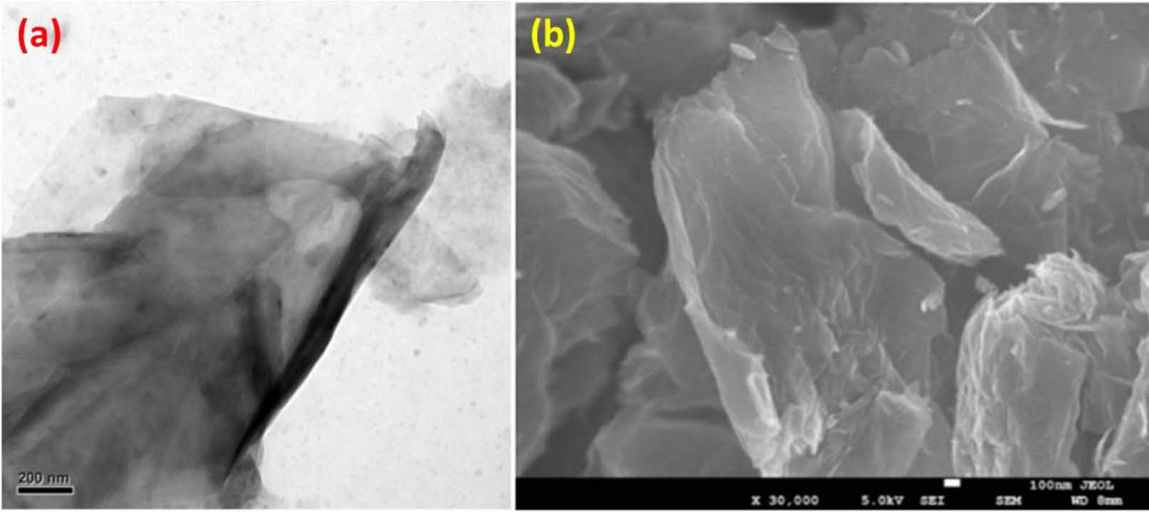
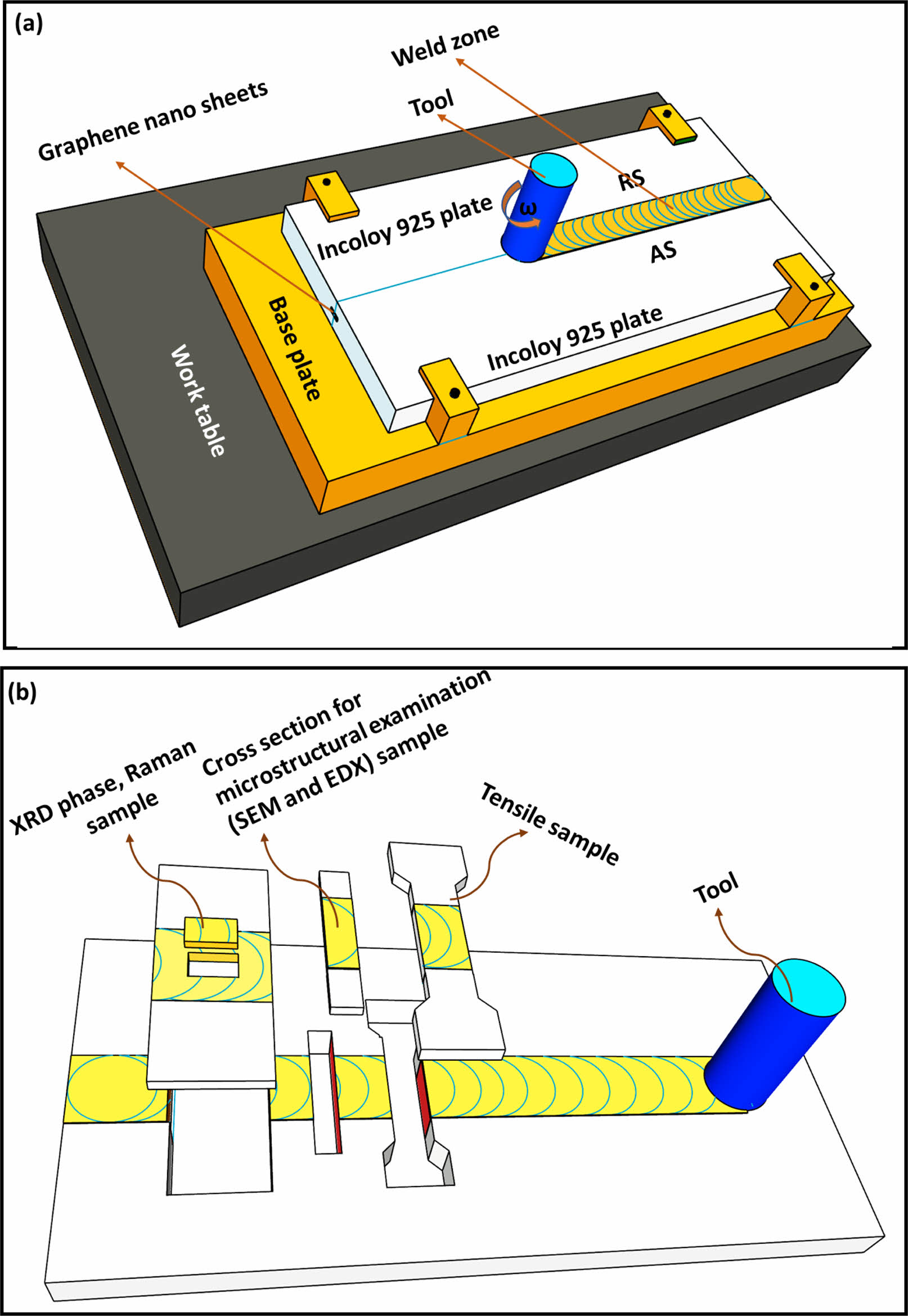
Incoloy 925 alloy sheets employed in this study were cut into 105 × 80 × 2 mm for fabrication of friction stir welding. The composition of Incoloy 925 used in welding is shown in Table 1. Graphene nanosheets with an average thickness of 5-10 nm, average lateral dimension <1 µm, surface area ~200-700 m2/g, and the number of layers 1-3 were used as reinforcement materials. Fig. 1. shows the graphene nanosheets obtained with TEM and FESEM. To introduce the graphene into the stirred area, machining created a groove (0.5 mm depth and 0.5 mm breadth on the faying surface of the Incoloy 925 alloy) at the interface between two specimens. An integrated groove was developed such that the graphene nanosheets (60 milligrams packed) remained trapped between the specimens, so there was no graphene leakage during the welding process. The schematic perspective of the graphene powder groove for friction stir welding was given in Fig. 2(a). In general, tool rotational speed has been found to influence grain refinement of material in FSW considerably. Various rotational speeds of 300 rpm, 400 rpm, and 500 rpm were employed in this investigation. The Tungsten carbide cobalt (WC-Co) tool was created with a pin diameter of 6 mm, a shoulder diameter of 18 mm, and a pin length of 1.8 mm. The optimum rotational speed and tool traverse speed gave better microstructural and mechanical properties at 400 rpm and 40 mm/min correspondingly by maintaining tool tilt angle as 3 deg. This experiment was carried out using a vertical milling machine (Make HMT FM-2, 10 HP, 3000 rpm). Inert gas (Argon gas) was applied to counter surface oxidation throughout welding.
The specimens for the microstructure study were polished to a mirror finish with various grades of emery sheets and etched with a solution of 97 ml of hydrochloric acid, 2 ml of nitric acid, and 1 ml of sulphuric acid. The interfacial microstructure was further examined using a Field Emission Scanning Electron Microscope (FESEM, Gemini 500 (M/s Carl Zeiss) and EDS (Energy Dispersive Spectroscopy). XRD analysis was carried out using Rigaku Miniflex 600, and Raman analysis was conducted using a confocal Raman microscope (WITec alpha300RA, Modal name: Alpha300RA AFM & RAMAN). A Microhardness test was performed using a Vickers hardness tester at the cross-section of NZ and normal to FSW direction with a load of 100 g and a dwell of 15 s. The tensile test specimens were prepared as per ASTM C-749 standards, and the tensile test was performed at room temperature in a servo-controlled universal testing machine with a crosshead speed of 0.5 mm/min (Make: FIE – BLUESTAR, INDIA, Model: UNITEK 94100). Three tensile specimens were used for each combination of process parameters, and the average results of these three tests were reported. A tensile test was performed on a Universal testing machine with 40KN capacity and loaded at 1.5 KN/min as per ASTM standards.
|
Fig. 1 (a) TEM and (b) FESEM images of the as-received GNPs. |
|
Fig. 2 (a) Schematic representation of Friction stir welding setup. (b) Schematic representation of various characterization. |

Using friction stir welding, Incoloy 925 sheets of reinforced graphene was investigated over a broad range of tool rotation speeds of 300-500 rpm and welding speeds of 20-100 mm/min. At welding speeds of 20, 30, and 40 mm/min, decent joints were established at a constant tool rotation speed of 400 rpm. All of these samples were utilized to study the mechanical and microstructure properties of the FSW Incoloy 925.
Microstructure
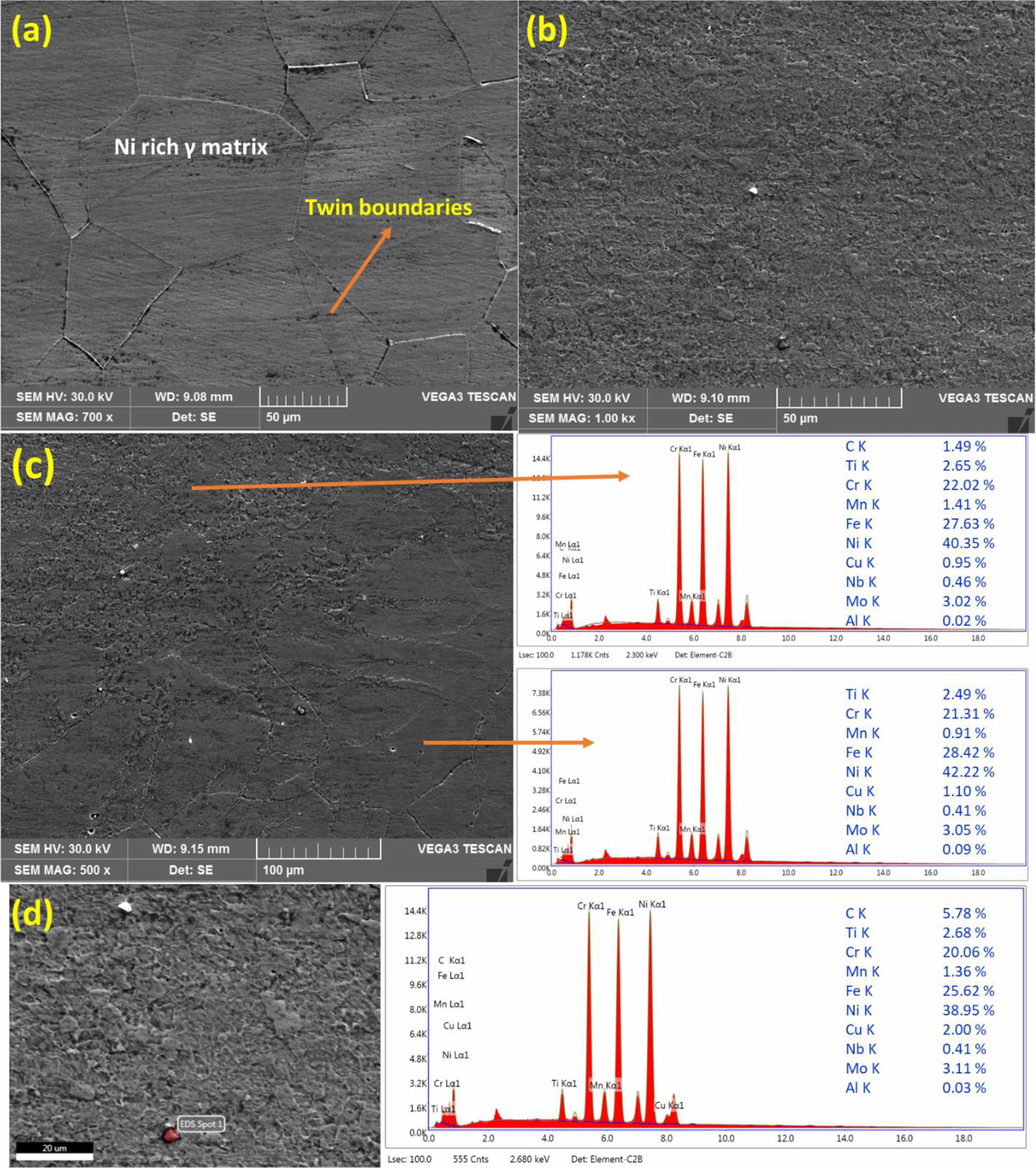
A FESEM image and EDX spectrum evaluation of the base metal, stir zone, interface between the base metal-stir zone, and carbon enriched regions were displayed in Fig. 3. Particles of graphene dispersed uniformly within the nugget zone due to the presence of dynamic stirring of the rotating tool during the friction stir welding, as shown in Fig. 3(b). This might be due to the groove being tangent to the tool pin, which results in a fine equiaxed grain structure in the stir zone.
The grain refinement was characterized by dynamic recrystallization (DRX) by significant deformation and temperature input using friction stir welding. This implies that the strain rates (stored energy) due to the plastic flow into the stirred area were enhanced during friction stir welding, the tool and material were involved in developing friction heat. The material used in this evaluation has lower stacking fault energy materials. As found with materials with a strong stacking fault force, such materials were subjected to DRX. Besides that, rearranging the dislocation through dynamic recovery was hard. Materials with lower stacking fault energies were organized further to recrystallize nuclei than materials with high stacking fault energy.
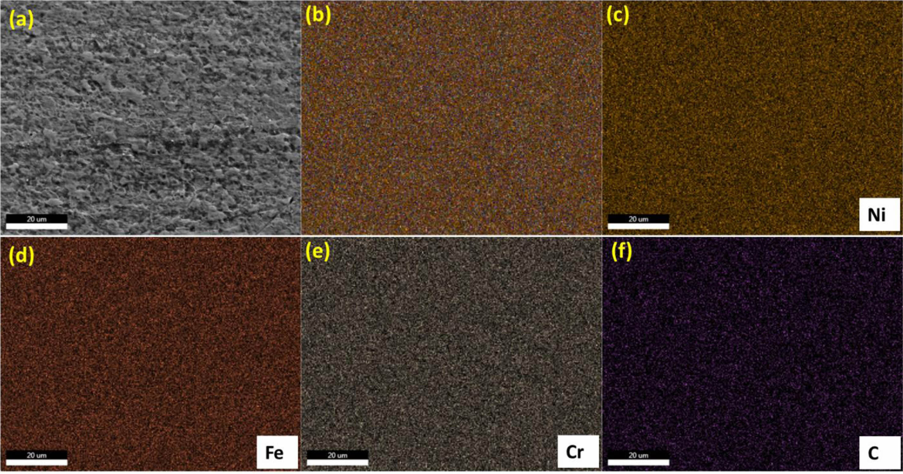
Besides, the development of dense recrystallization nuclei was significantly encouraged when higher dislocation density was associated with significant deformation during friction stir welding. Consequently, recrystallization nuclei produced during the grains and grain boundaries, propelling densities at dislocations. It was demonstrated in this method that the friction stir welding achieved grain refinement [29]. Fig. 4. shown the EDX elemental mapping of the friction stir region, revealing the distribution of main elements in the stir zone (Ni, Fe, Cr, and C). The stir region predominantly had a mixture of Ni-Fe-Cr matrix and distribution of graphene particles, as well as some other elements. The dispersed graphene particles uniformly distributed in the Ni-Fe-Cr matrix.
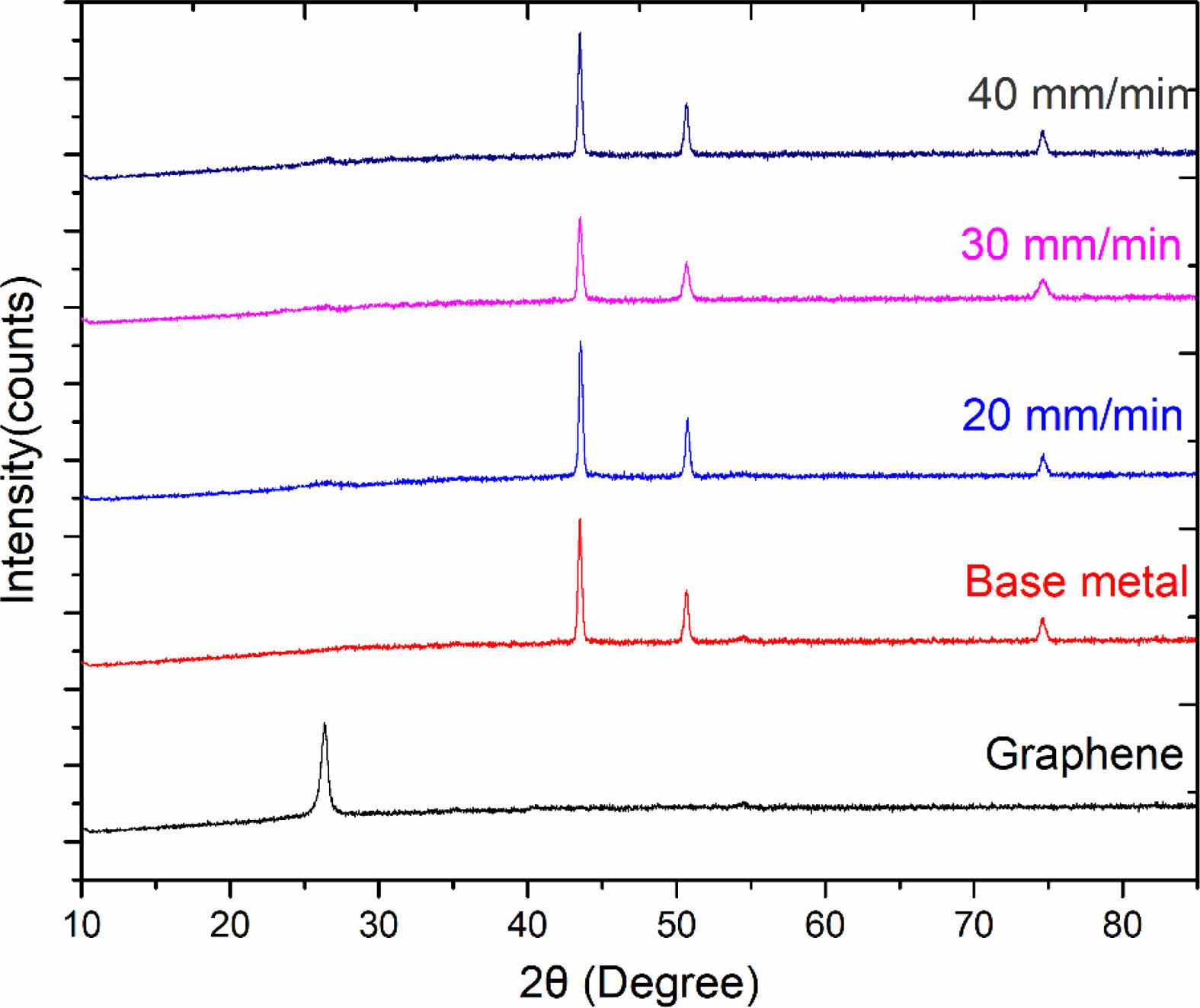
X-ray diffraction analysis
Fig. 5 shown a recorded X-ray diffractogram on the graphene, base metal, and stir zone (0.5 mm from the middle of the stir region (0 mm) on both advancing, retreating sides of the cross-section FSW Incoloy 925). The prominent peaks diffracted from (111), (200), and (220) correspond to the Incoloy 925 at the stir region. Furthermore, no other peaks were detected, suggesting that no phase change or oxidation occurred during the friction stir welding.
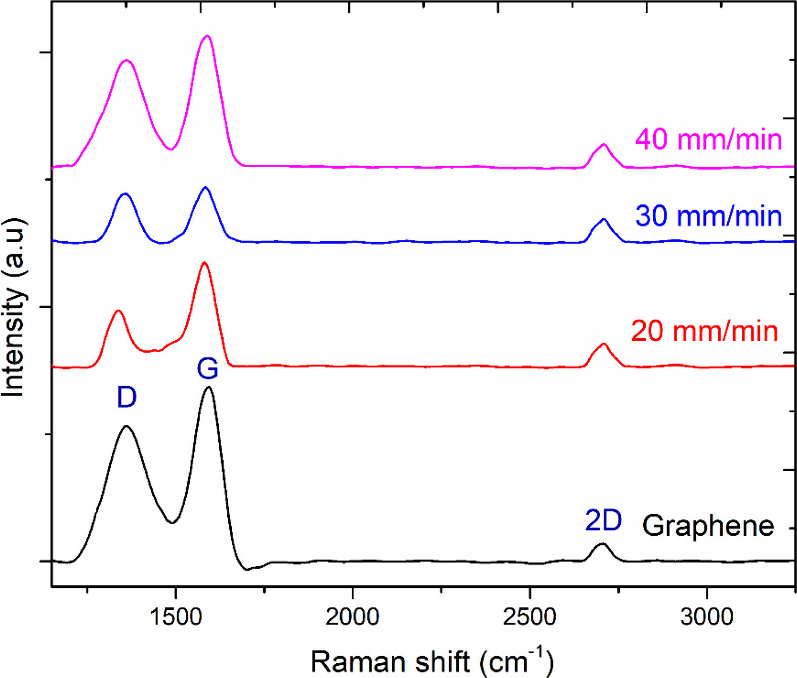
Raman spectroscopy
Raman spectroscopy was a beneficial instrument for detecting the presence of carbon-based materials and analyzing their defects. The Raman spectra of as-received graphene nanoparticles (GNP) and GNP present in the graphene-induced Incoloy 925 weld zone were revealed in Fig. 6. The G-band (with a wavelength of 1576 cm-1) was recognized as a unique band, which corresponds to sp2 graphene and reflects the vibration of the C-C bond. The D-band (with a wavelength of 1351 cm-1) in the spectrum described the disorder or flaw in the structure. The 2D band (with a wavelength of 2701 cm-1) shown the number and arrangement of stacking graphene layers connected with the structure.
Microhardness distribution
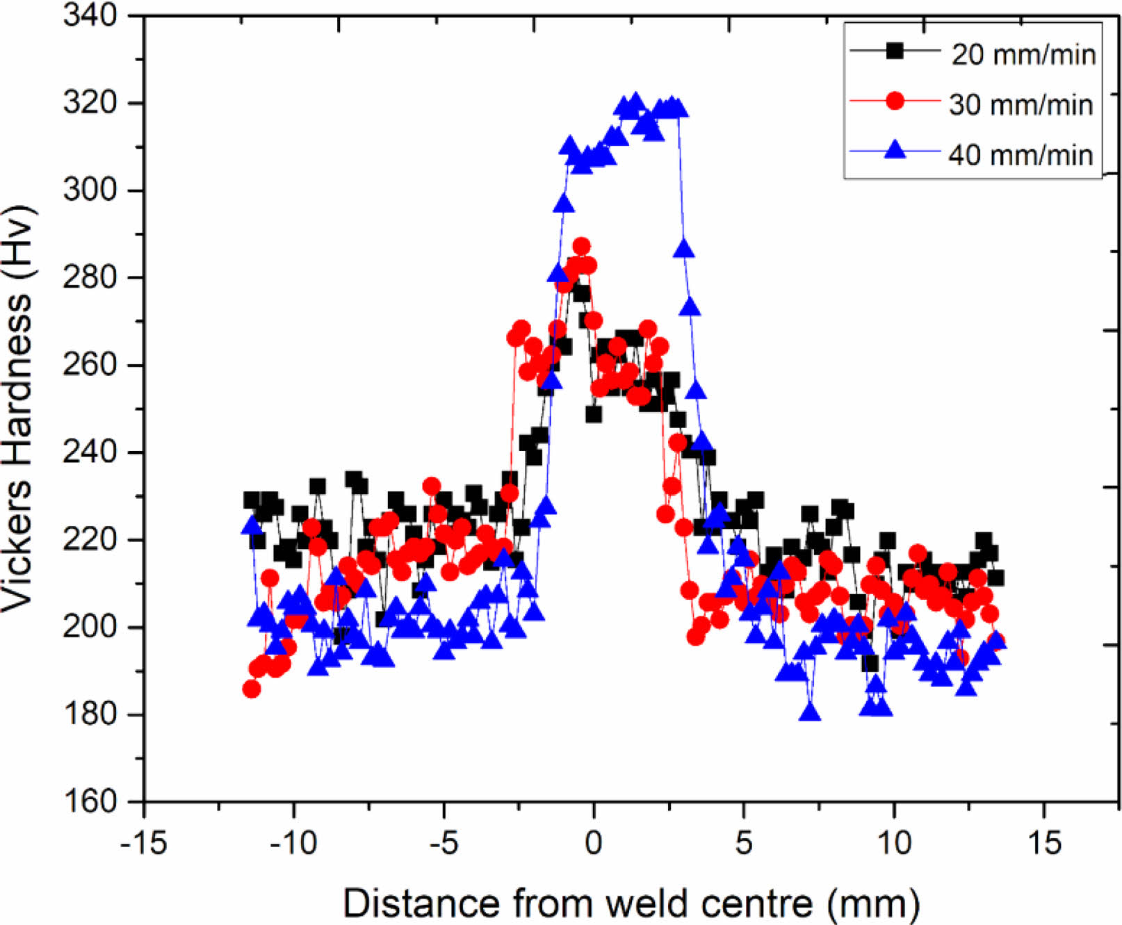
The hardness was measured across the weld by using Vickers hardness machine and micro-hardness distribution of the weld material was presented in Fig. 7. The joints were developed by FSW, hardness circulations within the stir zone were generally utilized to measure the mechanical strength. The Vickers hardness associated with the parent metal was 188-230 HV, having an average micro-hardness was 212 HV. The stir zone micro-hardness was achieved more than the base metal in the joints manufactured at 20 mm/min, reaching about 278 HV. At a 30 mm/min welding speed, the distribution rose to 290 HV in the stirred zone. Increasing the welding speed increased the micro-hardness; thus, the highest hardness value of 320 HV was observed in the stir zone for the sample processed at 40 mm/min welding speed, which was also one of the reasons for the improved tensile properties of these joints when compared to other joints.
According to the mixture rule, the increase in hardness was caused by grain size refinement and the high presence of graphene sheets in the stir zone. The continuous dynamic recrystallization due to the stirring action of the tool pin produces new nucleation locations leading to grain size reduction. On both the RS (retreating side) and AS (advancing side), the degree of hardness decreases as away from the welded joint (Fig. 5). According to the Hall-Petch relationship, the hardness of the welded zone increases as grain size decreases. As mentioned in section 3.1, the grain size of the nugget region was found to be smaller than that of the base metal, resulting in the nugget zone having the highest average hardness values.

H stands for hardness (HV), and d stands for average grain size in millimeters.
Finally, due to the fine, evenly distributed graphene particles and lack of defects, the graphene reinforced Incoloy 925 led to maximum hardness.
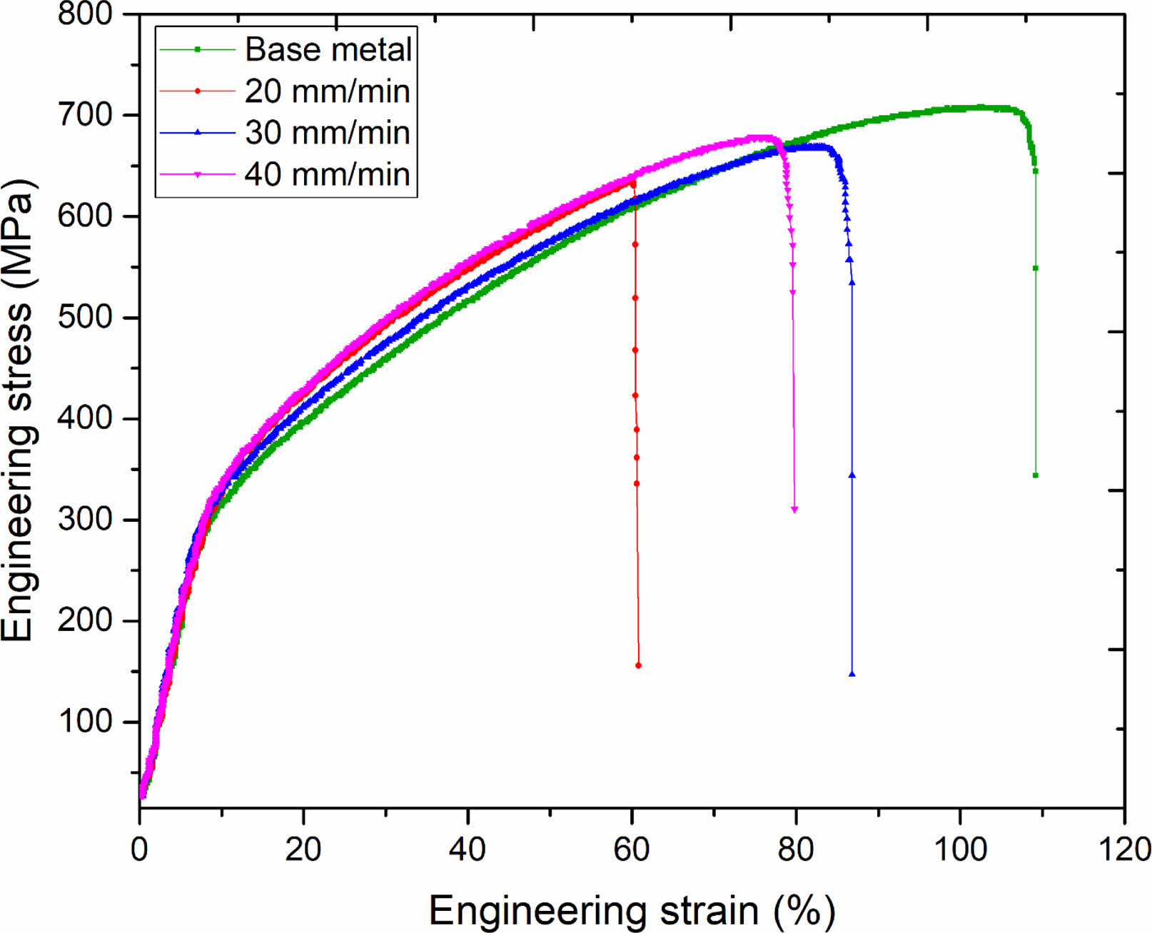
Tensile properties
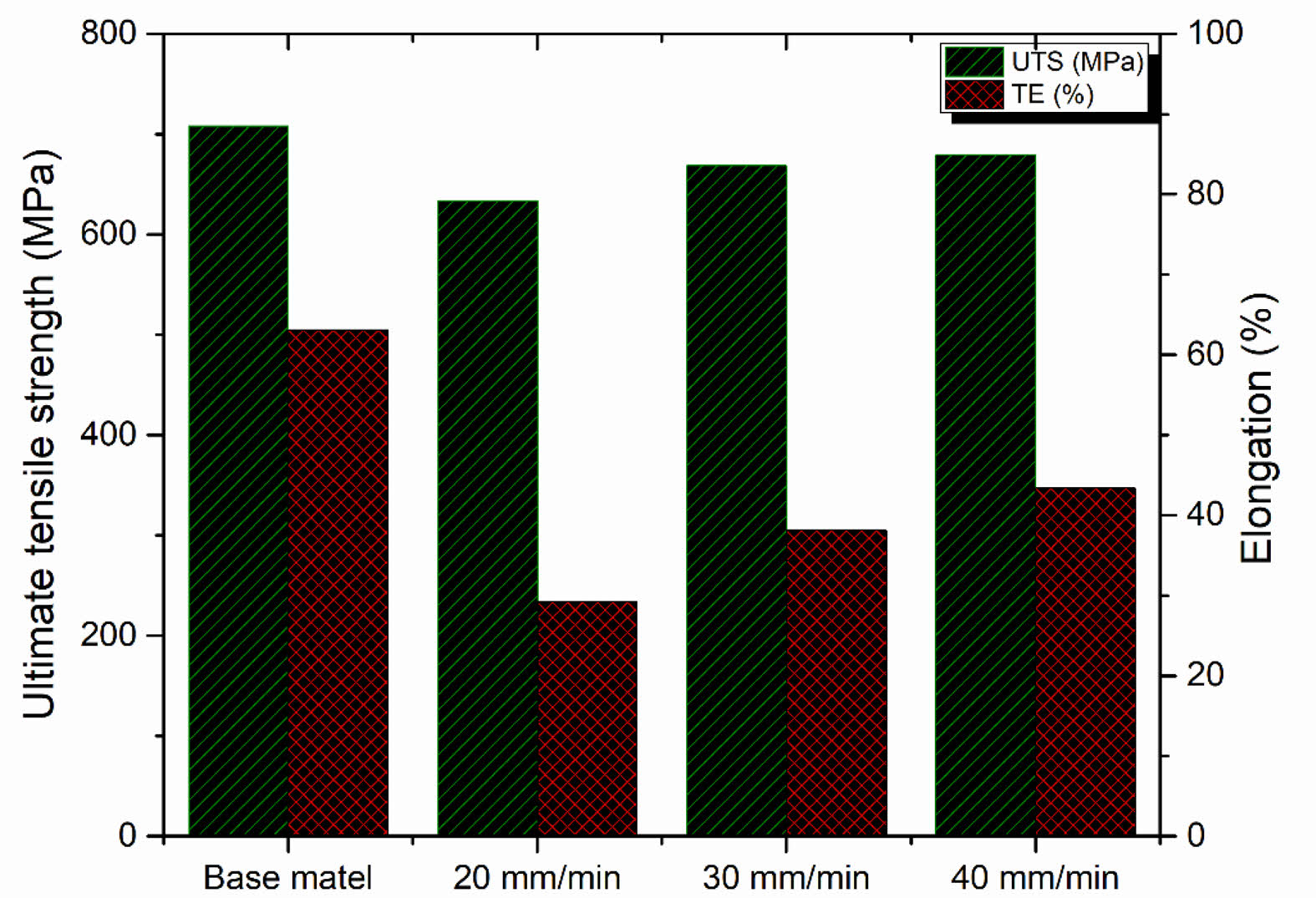
The mechanical properties were determined using tensile test specimens, these were made by using FSW at a tool rotation speed of 400 rpm and welding speeds of 20, 30, and 40 mm/min. The engineering stress-strain curve was shown in Fig. 8. The tensile properties were summarised in Fig. 9. In this investigation, friction stir welding of Incoloy 925 alloy joints produced joints with nearly identical tensile strengths parallel to their base metal. The base metal had a tensile strength of 695 MPa, while welding speeds of 20, 30, and 40 mm/min had tensile strengths of 626, 671, and 678 MPa, respectively. Every stir zone had higher hardness characteristics than the base metal, indicating that the stir zone did not deform during the tensile tests. Since strength is inversely proportional to hardness, the base metal area likely fails during the transverse tensile test. Henceforth, only the sample's base metal region was subjected to plastic deformation, reducing overall engineering pressure.
|
Fig. 3 SEM micrographs of (a) as received Incoloy 925 base metal (b) stir zone (c) SEM and EDX spectra of an interface between base metal- stir zone (EDX spectra revels equally graphene distribution in stir zone) (d) SEM and EDX spectra of graphene enriched region. |
|
Fig. 4 SEM-EDX mapping analysis of graphene reinforced Incoloy 925 alloy. (a) SEM image of the stir zone (b) EDX elemental mapping of the stir zone (c) EDX mapping of Nickel (d) EDX mapping of Iron (e) EDX was the mapping of Chromium (f) EDX mapping of carbon. |
|
Fig. 5 X-ray diffraction spectrum of as-received Graphene, Incoloy 925 base metal, friction stir welded Incoloy 925 with graphene at 20 mm/min, 30 mm/min, and 40 mm/min traverse speed. |
|
Fig. 6 Raman spectrum of as-received graphene, friction stir welded Incoloy 925 with graphene at 20 mm/min, 30 mm/min, and 40 mm/min traverse speed with D, G, 2D bands graphene showed at 1347 cm-1, 1577 cm-1 and 2713 cm-1 correspondingly |
|
Fig. 7 Distribution of Vickers hardness calculated during the midpoint perpendicular to the welding direction of grapheneinduced Incoloy 925 alloy specimens welded during the welding speeds of 20, 30, and 40 mm/min. |
|
Fig. 8 Engineering stress-strain curve of specimens milled in SZ of Graphene induced Incoloy 925 alloy welded at the welding speeds 20, 30, 40 mm/min, and base metal. |
|
Fig. 9 Tensile properties of Incoloy 925 base metal and friction stir welded graphene induced Incoloy 925. |
Friction stir welding of Incoloy 925 was successfully welded with reinforcement of graphene nanoparticles, and the following conclusions were obtained.
1) Graphene-induced Incoloy 925 was successfully welded by the friction stir welding, and defect-free welds were found under the following process parameters: tool rotational speed of 400 rpm and traverse speeds of 20, 30, 40 mm/min.
2) FSW resulted in the generation of the fine and equiaxed recrystallized grains, and the graphene nanoparticles were distributed uniformly in the nugget zone.
3) The hardness was increased by around 50% after friction stir welding. Due to grain refinement and harder phase materials, maximum hardness (320 HV) was obtained.
4) Graphene reinforced Incoloy 925 alloy weld joints exhibited high joint efficiency (from 90% to 97.5%).
The authors would like to thank the authorities of Koneru Lakshmaiah Education Foundation, Guntur, for providing facilities to carry out this work. The authors are also thankful to the Sophisticated analytical instrument facility (SAIF), Mahatma Gandhi University, Kottayam, for the Raman spectroscopy facility and Central Analytical Laboratory, BITS Hyderabad, for the powder X-ray diffraction facility
- 1. T. Sun, A.S. Tremsin, M.J. Roy, M. Hofmann, P.B. Prangnell, and P.J. Withers, Mater. Sci. Eng. A. 712(2018) 531-538.
-

- 2. M.M. El-Sayed, A.Y. Shash, M. Abd-Rabou, and M.G. ElSherbiny, J. Adv. Join. Process. 3(2021) 100059.
-
- 3. F. Weber, J. Gebhard, R. Gitschel, S. Goyal, M. Kamaliev, S. Wernicke, and A.E. Tekkaya, J. Adv. Join. Process. 3 (2021) 100054.
-
- 4. F. Gao, Y. Guo, W. Yu, P. Jiang, and Z. Liao, Mater. Character. 177(2021) 111121.
-
- 5. C. Chanakyan and S. Sivasankar, J. Ceram. Process. Res. 21(2020) 647-655.
-
- 6. H. Park, H. Youn, J. Ryu, H. Son, H. Bang, I. Shon, and I. Oh, J. Ceram. Process. Res. 13(2012) 705-712.
-
- 7. S. Balamurugan, K. Jayakumar, and K. Subbaiah, Arab. J. Sci. Eng. 46 (2021)11985-11998.
-
- 8. M.K. Abbass, S.K. Hussein, and A.A. Khudhair, Arab. J. Sci. Eng. 41(2016) 4563-4572.
-
- 9. B.D. Djarot and T. Marco, Eng. Sci. Technol. Int. 24(2021) 637-647.
- 10. X. Wang, Y. Morisada, and H. Fujii, J. Mater. Sci. Technol. 85 (2021) 158-168.
-
- 11. R. Pandiyarajan and M. P. Prabakaran, J. Ceram. Process. Res. 21(2020) 690-698.
-
- 12. R. Srinivasan, B. Suresh Babu, P. Prathap, R. Whenish, R. Soundararajan, and G. Chandramohan, J. Ceram. Process. Res. 22(2021) 16-24.
-
- 13. P. Gopi Krishnan, B. Suresh Babu, S. Madhu, S.J. Gowrishankar, C. Bibin, S. Saran, S. Shree Ram, A.R. Sri Hari, and S. Vidyasagar, J. Ceram. Process. Res. 22(2021) 483-489.
-
- 14. H. Zhang, B. Zhang, Q. Gao, J. Song, and G. Han, J. Manuf. Process. 68 (2020) 126-135.
-
- 15. S.S. Mirjavadi, M. Alipour, A.M.S. Hamouda, S. Kord, P.G. Koppad, Y.A. Abuzin, and R. Keshavamurthy, J. Manuf. Process. 36 (2018) 264-271.
-
- 16. Z. Meng, L. Zhu, C.S. Lim, K. Ullah, S. Yea, K. Cho, and W. Oh, J. Ceram. Process. Res. 14 (2013) 349-354.
-
- 17. M.M. Nasr, S. Anwar, A.M. Al-Samhan, H.S. Abdo, and A. Dabwan, J. Manuf. Process. 61(2021) 574-589.
-
- 18. X. Zhang, Y. Xu, M. Wang, E. Liu, N. Zhao, C. Shi, D. Lin, F. Zhu, and C. He, Nat. Commun. 11 (2020) 2775.
-
- 19. K.P. Nuckolls, M. Oh, D. Wong, B. Lian, K. Watenabe, T. Taniguchi, B.A. Bernevig, and A. Yadani, Nature 588(2020)610-615.
-
- 20. P.W. Sutter, J.-I. Flege, and E.A. Sutter, Nat. Mater. 7 (2008) 406-411.
-
- 21. J.N. DuPont, J.C. Lippold, and K.D. Samuel, Wiley, Hoboken, 2009.
- 22. S. Sujai and R.K. Devendranath, J. Manuf. Process. 54 (2020) 359-373.
-
- 23. Z. Shi, X. Yan, and C. Duan, J. Alloys. Compd. 652 (2015) 30-38.
-
- 24. K.H. Song and K. Nakata, Mater. Trans. 50(2009) 2498-2501.
-
- 25. G.V.B. Lemos, A.B. Farina, R.M. Nunes, P.H.C.P. Cunha, L. Bergmann, J.F. Santos, and A. Reguly, J. Mater. Res. Technol. 8 (2019) 2528-2537.
-
- 26. K.H. Song and K. Nakata, J. Alloys. Compd. 505 (2010) 144-150.
-
- 27. W. Xiao, S. Lu, Y. Wang, and J. Shi, Trans. Nonferrous Met. Soc. China. 28 (2018) 1958-1969.
-
- 28. O. Ogunbiyi, S. Salifu, R. Sadiku, T. Jamiru, O. Adesina, and O. Seun Adesina, Mater. Today Proc. 38 (2021) 743-748.
- 29. K.H. Song and K. Nakata, Mater. Des. 31 (2010) 2942-2947.
-
 This Article
-
2023; 24(2): 250-256
Published on Apr 30, 2023
- 10.36410/jcpr.2023.24.2.250
- Received on Aug 4, 2022
- Revised on Oct 18, 2022
- Accepted on Nov 17, 2022
Services
- Abstract
introduction
experimental procedure
results and discussion
conclusion
- Acknowledgements
- References
- Full Text PDF
Shared
Correspondence to
- Varalakshmi Penugonda
-
aDepartment of Mechanical Engineering, Koneru Lakshmaiah Education Foundation, Guntur Andhra Pradesh, 522502, India
bDepartment of Mechanical Engineering, Guru Nanak Institute of Technology, Hyderabad, Telangana, 501506, India
Tel : +91-863-239-9999 Fax: +91-863-238-8999 - E-mail: me2010.varam@gmail.com
Clean-Energy Research Institute(CRI), Hanyang University, 222, Wangsimni-ro, Seongdong-gu, Seoul, 04763, Korea
E-mail: jcpr@hanyang.ac.kr