


- Ultrashort pulse laser processing of ZrO2 ceramics
Qibiao Yanga, Yunhan Youa, Bojin Chenga, Lie Chena, Jian Chenga, Deyuan Loua,Yutao Wangc and Dun Liub,*
aLaser Group, School of Mechanical Engineering, Hubei University of Technology, Wuhan 430068, People's Republic of China
bKey Lab of Modern Manufacture Quality Engineering, Hubei University of Technology, Wuhan 430068, People's Republic of China
cShanghai Institute of Laser Technology, Shanghai Keylab of Laser Beam Micro Processing, Shanghai 200233, People's Republic of ChinaThis article is an open access article distributed under the terms of the Creative Commons Attribution Non-Commercial License (http://creativecommons.org/licenses/by-nc/4.0) which permits unrestricted non-commercial use, distribution, and reproduction in any medium, provided the original work is properly cited.
It is crucial to investigate the mechanism of ultrashort pulse laser processing of ZrO2 ceramics to improve its processing accuracy and efficiency. An ultrashort pulse laser was used to fabricate square grooves on the surface of ZrO2 ceramics. The depth, surface roughness, and surface topography of grooves were analyzed by the laser confocal microscope, optical profiler, and scanning electron microscope. The effects of different laser parameters on the material removal efficiency and processing quality of ZrO2 ceramics were studied. The results show that as the laser fluence increases, material removal efficiency first increases and then decreases, while the surface roughness first decreases and then increases. The heat accumulation effect is severe when using high repetition frequency, and the processed surface shows melt damage. As the pulse width increases from 390fs to 6ps, the ablation threshold increases from 1.28 J/cm2 to 1.92 J/cm2. However, the material removal efficiency decreases gradually. Furthermore, the material removal efficiency in burst mode significantly reduces due to the plasma shielding and redeposition of distinct granular deposits within the grooves. These findings can serve as a guide for controlling and optimizing the process parameters of an ultrashort pulse laser processing of ZrO2 ceramics
Keywords: Ultrashort pulse laser, Laser processing, ZrO2 ceramics, Surface roughness, Removal efficiency
ZrO2 ceramics are widely used in the biomedical field due to their high strength, wear resistance, corrosion resistance, and good biocompatibility [1]. However, ZrO2 ceramics have low fracture toughness, high hardness, and challenging cutting characteristics such as low processing efficiency and severe tool wear [2]. The ultrashort pulse laser offers significant advantages for the processing of hard and brittle materials due to the little thermal effect, good consistency, and high precision [3]. Therefore, it is of great significance to study the ultrashort pulse laser processing mechanism of ZrO2 ceramics to improve the processing accuracy and efficiency. Thermal effects can be effectively avoided due to the nonlinear phenomena such as multiphoton ionization [4] and avalanche ionization [5] triggered during the interaction of ultrashort pulsed lasers with materials [6]. However, the heat accumulation and plasma shielding during ultrashort pulse laser processing reduce the processing efficiency and quality. The material removal mechanism in ultra-short pulse laser processing can be divided into strong ablation and weak ablation regimes depending on the laser power. The removal mechanism in the weak ablation case is mainly gasification, whereas in the strong ablation case it is mainly material heating and explosion [7]. It has been reported that heat accumulation and plasma shielding effects depend on the pulse time interval [8]. When processing in pulse burst mode, the energy of the second pulse is absorbed in the plasma generated by the first pulse, resulting in a significant reduction in material removal efficiency [9-10]. It was found that reducing the single pulse energy and increasing the repetition frequency and pulse number can overcome the plasma shielding effect and improve the ablation efficiency [11]. At high laser power and repetition frequency, the short pulse interval and the continuous action of multiple pulses increase surface defects and lower the ablation threshold, resulting in a cumulative effect [12]. In addition, the heat accumulation may cause surface stress concentration and thermal crack propagation [13], and then the material structure and composition change because of the high-temperature environment [14].
At present, there are few studies on ultrashort pulse laser processing of hard-brittle materials, and the interaction mechanism between ultrashort pulse laser and hard-brittle materials is still unclear. In this paper, the ultrashort pulse laser is used to fabricate rectangular groove structures on ZrO2 ceramics. The influence of various parameters of ultrashort pulse laser on the material removal mechanism of ZrO2 ceramics is studied. It will serve as a theoretical foundation for the efficient and precise machining of ZrO2 ceramic with ultra-short pulse lasers.
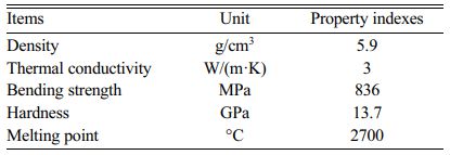
In this experiment, finished ZrO2 ceramics sheets with a size of 50 × 50 × 3 mm3 manufactured by Guangzhou Xinfeng Electronic Technology Company of China were investigated. The purity of the ZrO2 samples is 94% and their main properties indexes are shown in Table 1. The surface roughness of the pristine sample is 2.26 µm. The sample was cleaned before the experiment in an ultrasonic cleaner (DR-MS07) for 15 min and then dried in air.
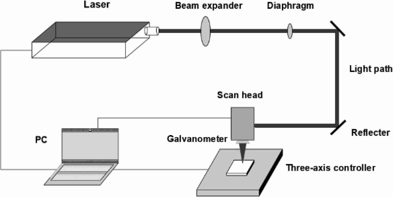
The femtosecond pulsed laser (YSL FemtoYL-50) with a wavelength of 1030 nm and a spot diameter of 21 µm was used. The schematic diagram of the femtosecond pulsed laser processing system is shown in Fig. 1. The square grooves with a side length of 1.5 mm were fabricated on ZrO2 samples using different laser parameters. The processed samples were also cleaned in an ultrasonic cleaner for 15 min and then dried in air. The laser confocal microscope (VK-X3000), the optical profiler (GT-K0, Bruker), and the scanning electron microscope (Hitachi, SU8010) were used to measure groove depth, surface roughness, and micro-morphology of the square groves, respectively.
|
Fig. 1 Schematic of the femtosecond laser processing system. |
The material removal efficiency is an important indicator to characterize the processing efficiency. The removal efficiency of laser processing refers to the volume of material removed per unit of pulse energy, and it is calculated as [15]:
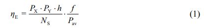
where h is the groove depth, f is the repetition frequency, Px is the lateral pulse spacing, Py is the hatch distance, NS is the number of scans, and Pav is the average power. The relationship between the removal efficiency and the laser fluence is given as:

where δ is the energy penetration depth, Fth is the ablation threshold, and F0 is the laser fluence.
Effect of pulse width
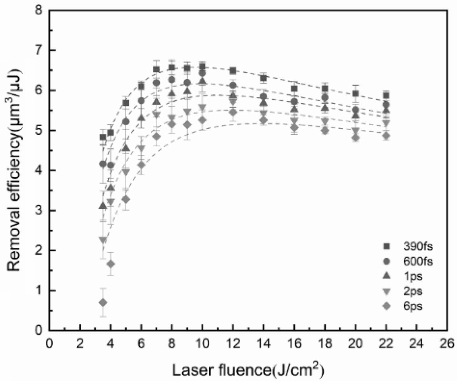
The removal efficiency under different laser parameters can be calculated by using Eq. (1). Figure 2 shows the variation trend of the removal efficiency with increasing laser fluence when the repetition frequency is 1000 kHz, the number of scans is 50, the spot overlap rate is 60%, and the pulse width is from 390 fs to 6 ps. The removal efficiency of different pulse widths first increases and then decreases with increasing laser fluence in the range of 3.5-22 J/cm2. The shorter is the pulse width, the higher is the removal efficiency. When the laser fluence is 3.5 J/cm2, the removal efficiency of a 390 fs laser pulse is much higher than that of a 6 ps laser pulse. As the laser fluence increases, the energy absorbed by the material increases, and the sample is rapidly heated and directly gasified, resulting in the significant improvement of the removal efficiency. When the laser fluence exceeds 10 J/cm2, the removal efficiency gradually decreases because of the plasma shielding effect due to the decrease in the effective processing laser energy [16].
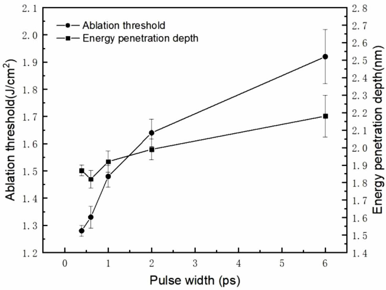
Eq. (2) is used to fit the experimental data to determine the energy penetration depth and ablation threshold. Figure 3 shows the variation trend of ablation threshold and energy penetration depth when the repetition frequency is 1000 kHz, the number of scans is 50, the spot overlap rate is 60%, and the pulse width is in the range of 390 fs-6 ps. As the pulse width increases from 390 fs to 6ps, the ablation threshold increases from 1.28 J/cm2 to 1.92 J/cm2, and the energy penetration depth increases from 0.03 nm to 0.12 nm. This is because ZrO2 ceramic is wide bandgap dielectrics [17], and impurities in the crystal can enhance laser energy absorption [18]. The concentration of free electrons increases rapidly under the action of ultrashort pulsed laser due to the multiphoton and avalanche ionization. When the pulse width increases, the duration of avalanche ionization increases, as does the free electron concentration [19]. The time for free electrons to transfer to the lattice becomes longer, resulting in a large depth of energy penetration. Since the pulse energy has a Gaussian distribution, the continuous increase of the pulse width leads to the decrease of peak laser power, increasing the proportion of heating energy and a decrease in the proportion of laser etching energy [20].
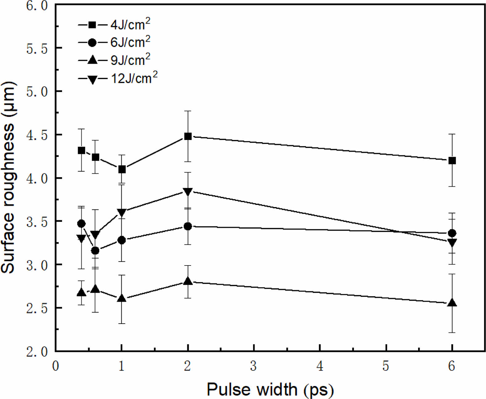
Figure 4 depicts the variation behavior of surface roughness with the laser fluence under different pulse widths. It can be seen that pulse width has less influence on surface roughness than laser fluence, and low or high laser fluence will lead to large surface roughness. This is because when the laser fluence is low, the material is mainly heated, and the material cannot be removed cleanly. When the laser fluence is high, the surface roughness increases because the thermal side effect increases when the material absorbs excess laser energy. Therefore, only the appropriate laser fluence can effectively reduce the surface roughness.
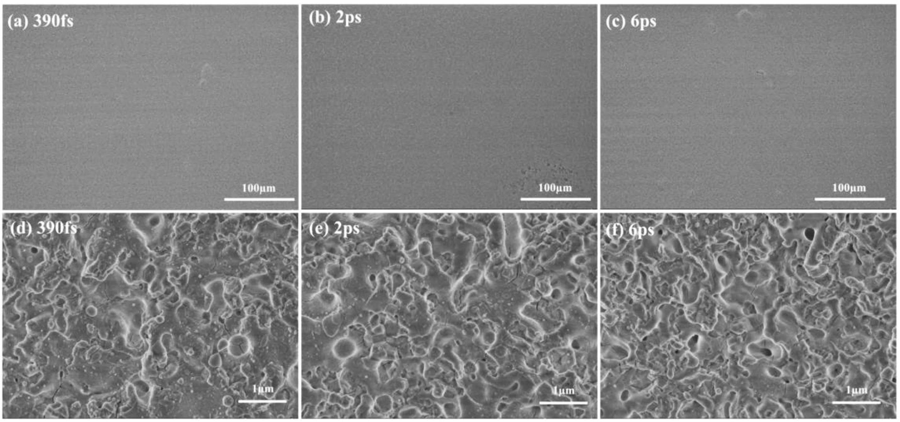
When the repetition frequency is 1000 kHz and the energy density is 9 J/cm2, the micro morphology with different pulse widths is shown in Fig. 5. The results show that both femtosecond and picosecond lasers can produce smooth surfaces at the optimal laser fluence. However, the surface processed by 390 fs pulsed laser is covered by a large number of micro particles. This is due to the fact that at higher values of the laser fluence, the electrons absorb a large amount of energy and undergo tunneling ionization to intensify the crystal phase transition [21], and the surface is explosively transformed into a mixture of material vapor and fine droplet-like particles, resulting in a liquid phase explosion [22]. The large amount of energy deposited by the ultrashort pulse in such a short time leads to the generation of stress, which promotes the crystal fracture and the formation of cavities and microcracks [23]. With the increase of pulse width, the interaction intensity between the pulse and the material decreases, and the number of micro particles on the surface of the material decreases gradually.
Effect of repetition frequency
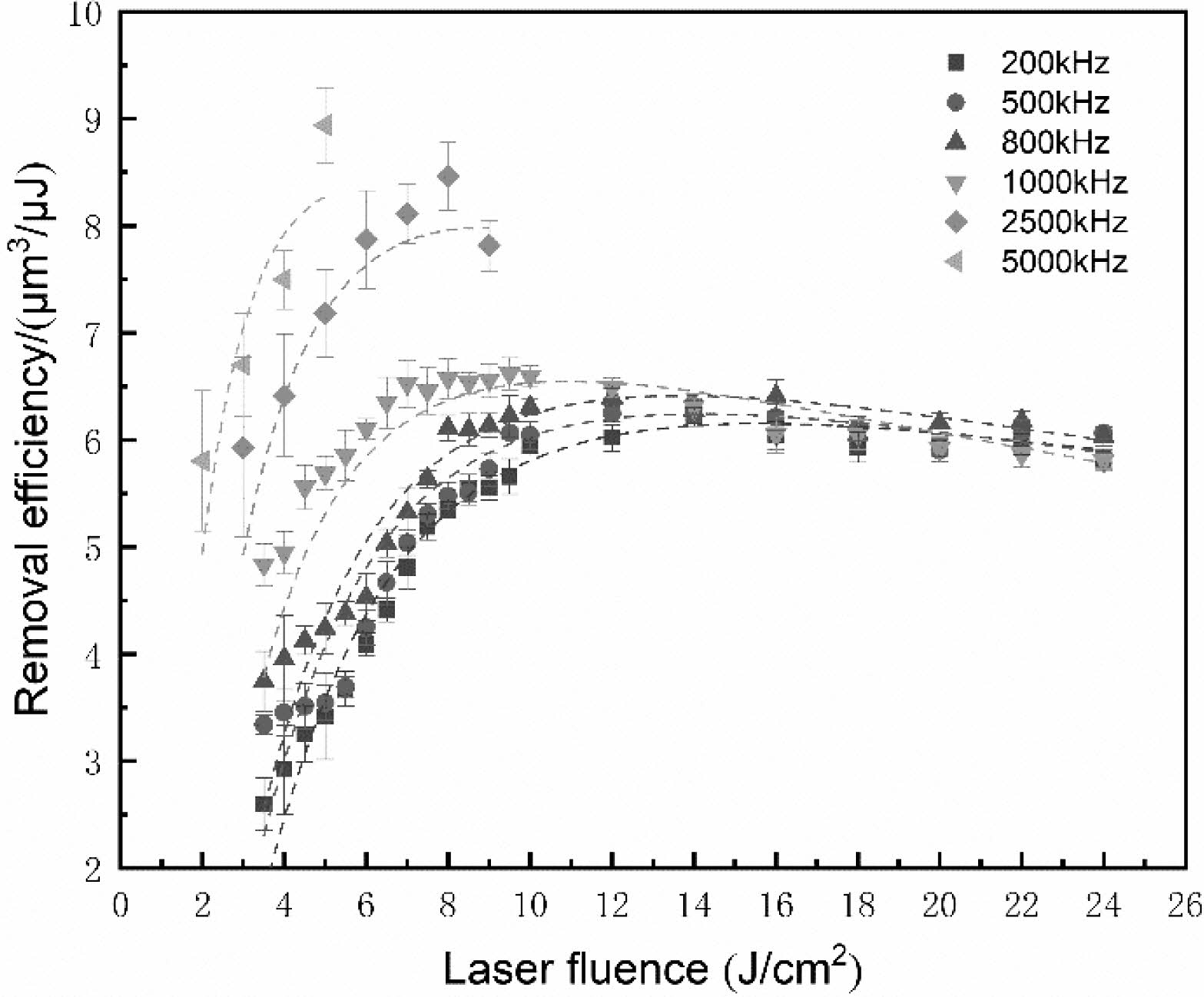
Figure 6 shows the removal efficiency as a function of the laser fluence for different repetition frequencies when the pulse width is 390 fs, the spot overlap rate is 60%, and the number of scans is 50. It can be seen that when the repetition frequency is between 200 kHz and 1000 kHz and the laser fluence is lower than 12 J/cm2, the material removal efficiency increases with the repetition frequency. As the laser fluence continues to increase, the removal efficiency gradually decreases. When the repetition rate is between 2500 kHz and 5000 kHz, higher material ablation efficiencies can be achieved even at lower laser fluence levels. This is due to the reason that at high repetition frequency, the laser pulse interacts with the surface for a short time, resulting in a strong heat accumulation at the surface.
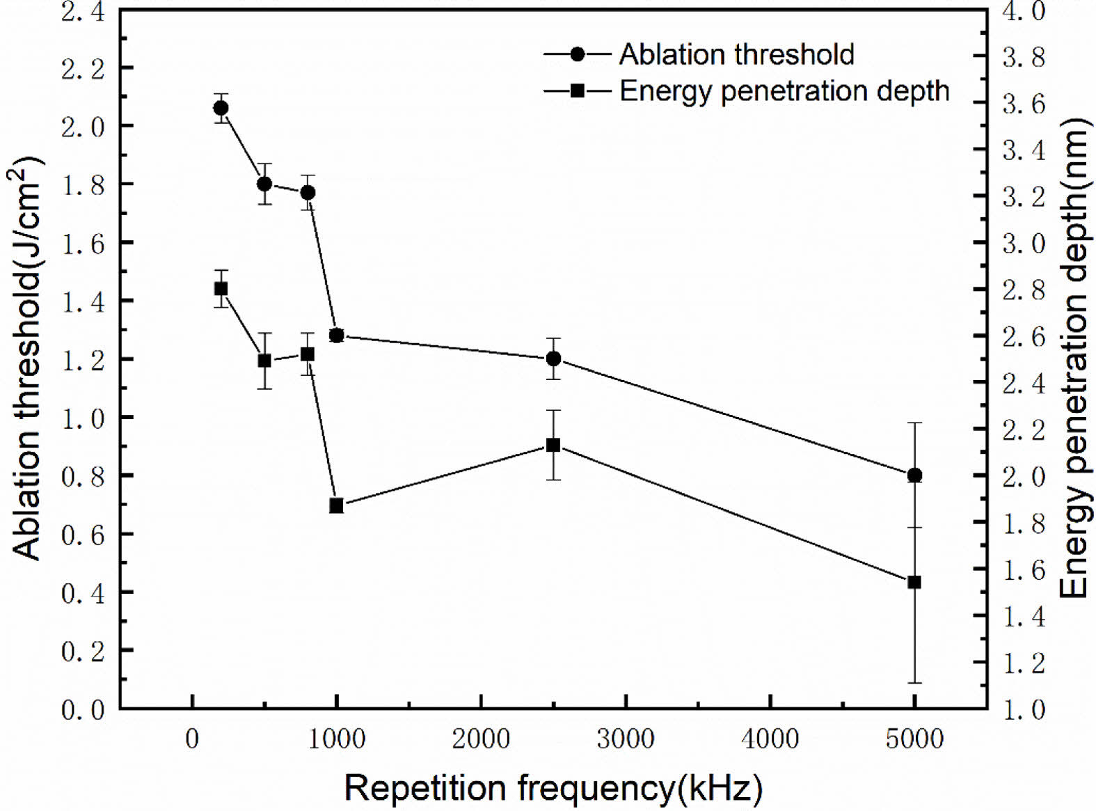
When the pulse width is 390 fs and the number of scans is 50, the variation of the energy penetration depth and ablation threshold under different repetition frequencies is shown in Fig. 7. As the repetition frequency increases from 200 kHz to 5000 kHz, the ablation threshold decreases from 2 J/cm2 to 0.8 J/cm2, and the energy penetration depth decreases from 2.8 nm to 1.54 nm.This is because when the surface temperature exceeds the melting or boiling point, the material is removed, as well as some of the heat is taken away. When the repetition rate is lower, the heat is dissipated due to the longer pulse interval. As the repetition frequency increases, the heat generated by a pulse does not completely dissipate before the incidence of a new pulse, consequently, the heat will accumulate and gradually increase. The cumulative effect becomes more apparent as the repetition frequency increases, resulting in the decrease of ablation threshold [24]. The energy penetration depth decreases with the increase of the repetition frequency due to the enhancement of the plasma shielding at high repetition frequency. The increase of removal efficiency with repetition frequency may be due to the fact that the heat accumulation effect can compensate for the plasma shielding effect.
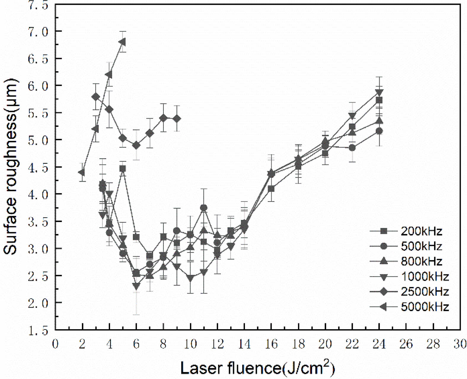
The variation of the surface roughness as a function of laser fluence for different repetition frequencies is shown in Fig. 8. The surface roughness does not seem to vary in the 200-1000 kHz frequency range. However, the surface roughness first decreases and then increases with the increase of the laser fluence. In the repetition frequency range of 2500-5000 kHz, the surface roughness is relatively large due to the severe heat accumulation. As the laser fluence increases at the repetition frequency of 5000 kHz, the amount of heat accumulation and surface roughness gradually increases.
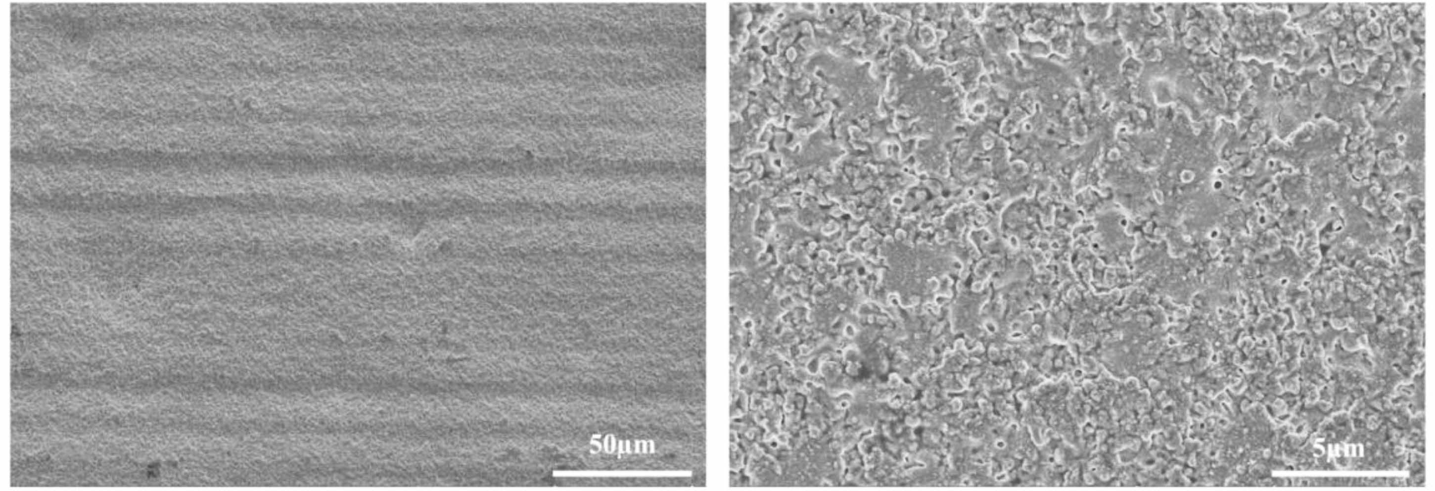
Figure 9 shows the micro-morphology of ZrO2 ceramics when the pulse width is 390 fs, the laser fluence is 4 J/cm2, and the repetition frequency is 2500 kHz. It can be seen that the processed surface is uneven, showing micro grooves of different widths, and the surface of ZrO2 ceramics is covered by melted particles. This is because when the repetition frequency is too large, the heat accumulation effect is strong, resulting in the heat is not easy to dissipate, and the hot melt damage is formed on the machined surface.
Effect of pulse burst
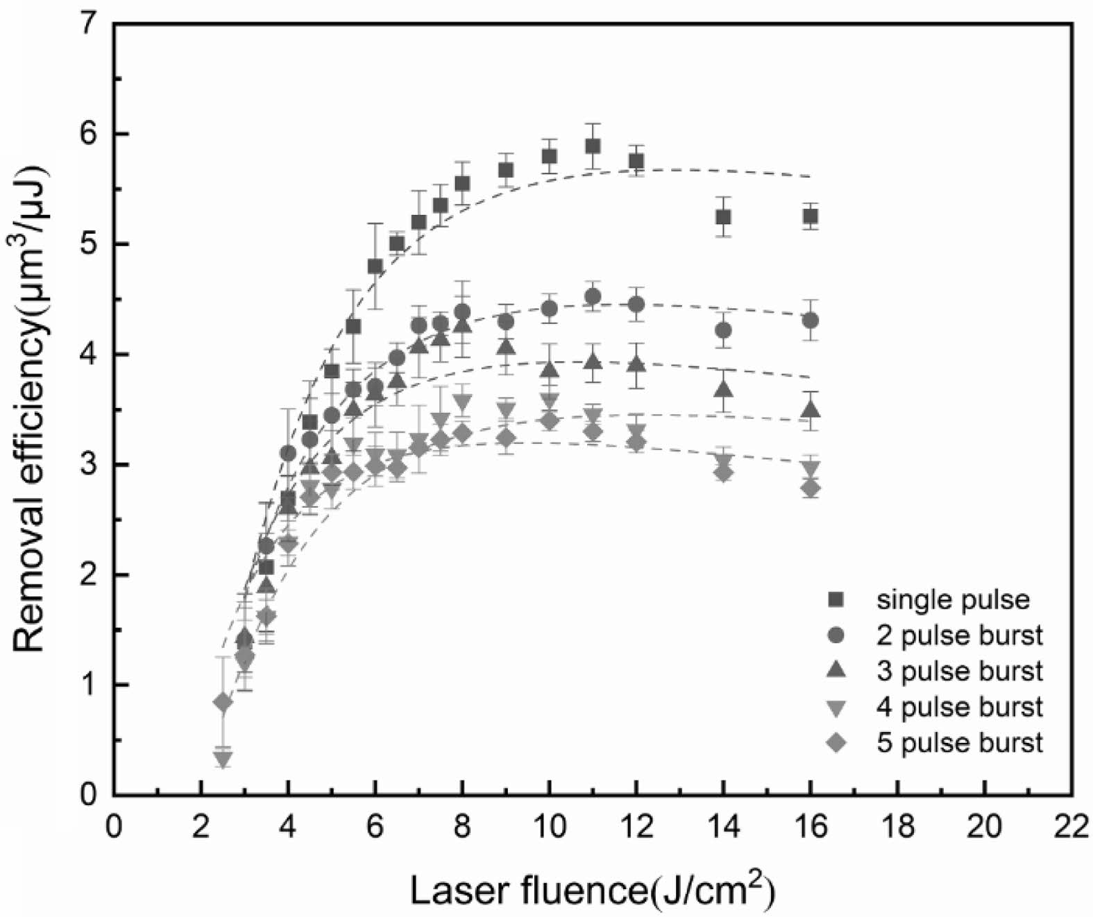
The scan time is adjusted to maintain a constant number of output pulses in a burst. When the number of sub-pulses is 1, 2, 3, 4, and 5, the corresponding scan times are 60, 30, 20, 15, and 12. The variation of removal efficiency as a function of laser fluence for different pulse bursts of 200 kHz frequency, 390 fs pulse width, and 60% spot overlap rate is shown in Fig. 10. When the laser fluence is less than 5 J/cm2, the material removal efficiency of the single-pulse and the burst modes is nearly identical. However, the removal efficiency of the single-pulse becomes higher than that of the burst as the laser fluence increases, which is attributed to the direct vaporization or ionization at higher laser intensities, forming high-pressure vapor and plasma above the surface after about 10 ns. Since the interval between two consecutive pulses is extremely short, the subsequent pulse energy is absorbed and/or reflected by the plasma induced by the previous pulse, resulting in a decrease of effective pulse energy that is deposited on the target surface. At the same time, the subsequent pulses interact with the vapor particles present above the surface, which are get heated and redeposited on the surface [25].
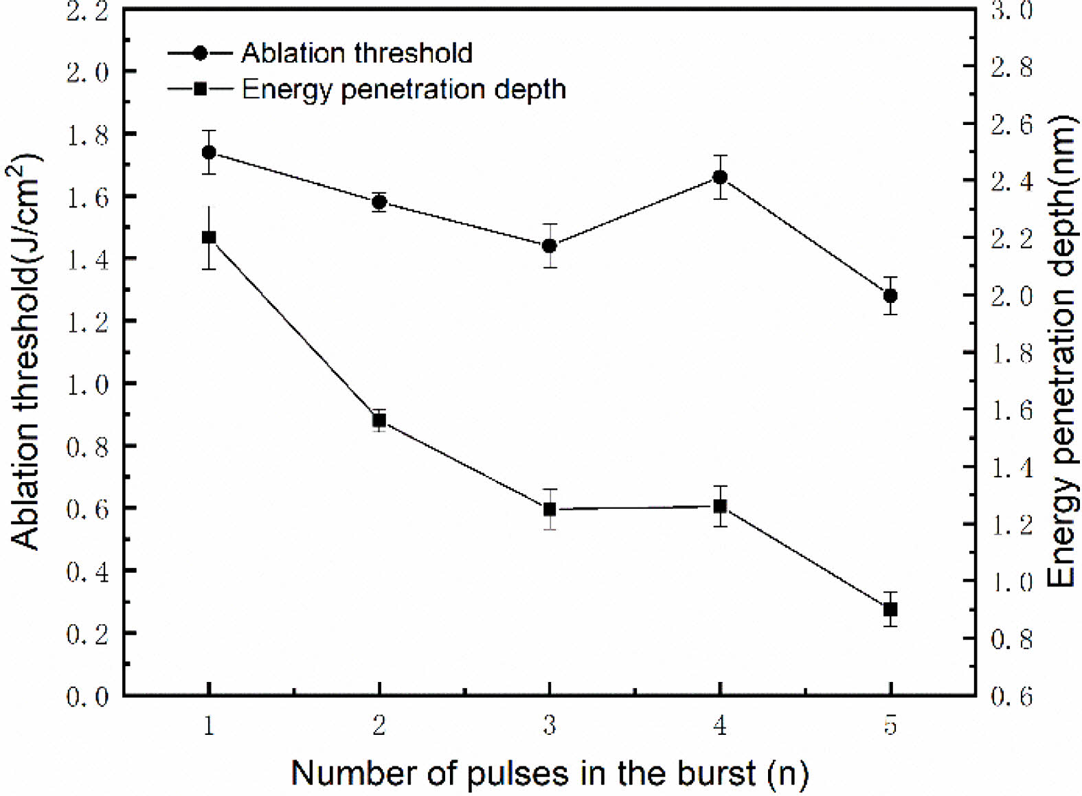
Figure 11 shows the variation of ablation threshold and energy penetration depth for different pulse-bursts. As the number of sub-pulses increases to five, the ablation threshold decreases from 1.74 J/cm2 to 1.28 J/cm2, and the energy penetration depth decreases from 2.2 nm to 0.9 nm. Due to extremely short pulse intervals in the pulse burst, the heat accumulation occurs under the continuous impact of multiple sub-pulses, and the temperature of the target material increases rapidly, which promotes material removal. However, the energy of a pulse burst is related to the number of sub pulses. When the laser fluence of a single pulse is equal, the more the number of sub pulses, the greater the energy of the pulse burst. Large laser fluence and short sub pulse time interval will produce a strong plasma shielding effect, so the energy penetration depth decreases rapidly with the increase of the number of sub pulses. When the heat accumulation effect cannot compensate for the plasma shielding effect, the removal efficiency gradually decreases.
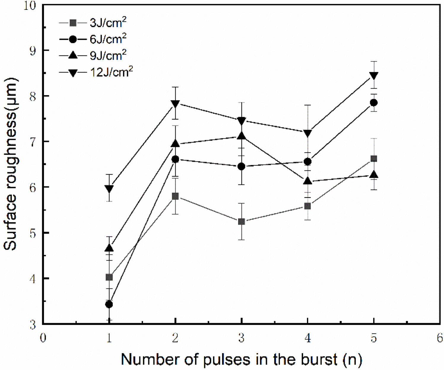
Figure 12 depicts the variation of the surface roughness with the number of pulse bursts. The results show that the surface roughness increases with the increase of sub pulse number and laser fluence. The surface roughness of the sample processed with a single pulse is smaller as compared to the sample processed with the pulse-bursts.
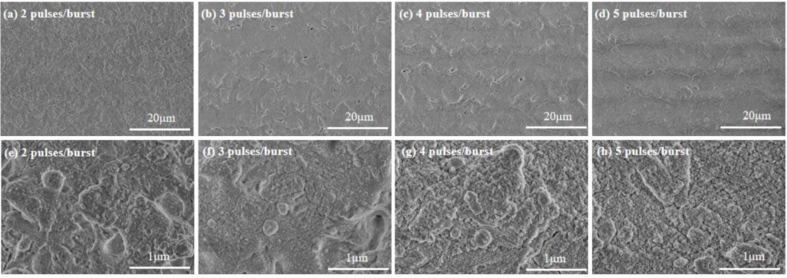
The micro-morphology under different pulse bursts for repetition frequency of 200 kHz, the pulse width of 390 fs and the laser fluence of 10 J/cm2 is shown in Fig. 13. There is clear redeposition of material on the sample surface in the pulse burst mode. When the pulse burst consists of 2 sub-pulses, a large number of fine molten particles are deposited on the processed surface. The cavity disappears as the number of sub-pulses in the pulse burst increases, the number of holes gradually decreases, and the deposited high-temperature molten particles gradually increase and adhere to the surface. This also explains why using pulse train mode processing will lead to the increase of surface roughness.
|
Fig. 2 Material removal efficiency versus laser fluence for different pulse widths. |
|
Fig. 3 Ablation threshold and energy penetration depth at different pulse widths. |
|
Fig. 4 The variation of the surface roughness with pulse width |
|
Fig. 5 SEM micrograph of ZrO2 ceramics samples processed with different pulse width. |
|
Fig. 6 Material removal efficiency versus laser fluence for different repetition frequency. |
|
Fig. 7 Ablation threshold and energy penetration depth for different pulse repetition frequency. |
|
Fig. 8 Relationship of laser fluence and surface roughness for different pulse repetition frequency. |
|
Fig. 9 SEM micrograph of ZrO2 ceramic processed with a repetition frequency of 2500 kHz. |
|
Fig. 10 Material removal efficiency versus laser fluence for different pulse bursts. |
|
Fig. 11 Ablation threshold and energy penetration depth for different pulse-bursts. |
|
Fig. 12 The variation of the surface roughness with the number of pulse bursts. |
|
Fig. 13 SEM micrograph of ZrO2 ceramics samples processed with different pulse-bursts. |
In this paper, an ultrashort pulse laser is used to process ZrO2 ceramics, and the influence of laser parameters on the processing of ZrO2 ceramics is studied. The conclusions of this study are as follows:
(1) In femtosecond laser processing, ZrO2 ceramics have a lower ablation threshold, higher removal efficiency than picosecond laser processing. Furthermore, one can improve removal efficiency and reduce surface roughness by choosing the appropriate laser fluence.
(2) When the laser fluence and the spot overlap ratio are constant, the ablation threshold of ZrO2 ceramics decreases, and the removal efficiency increases with the increase of repetition frequency. When the repetition frequency is 2500 kHz, the surface roughness rapidly increases, the heat accumulates, and the processed surface becomes uneven, causing hot melt damage.
(3) The material removal efficiency decreases with the increase of the number of sub-pulses in a pulse burst due to the plasma shielding effect. The surface roughness of ceramic increases as the fine molten particles adhere.
This work was supported by Key Research and Development Project of Hubei Province (Grant No. 2021BAA172) and Characteristic Innovation Research Project of Teachers (Grant No.2021XJZZ14).
The authors declare that they have no conflicts of interest.
- 1. M. Yoshinari, Dent. Mater J. 39[1] (2020) 37-45.
-

- 2. K.H. Lee, S.H. Ahn, and K.W. Nam, J. Ceram. Process. Res. 19[3] (2018) 183-188.
-
- 3. K.R. Kim, J.H. Kim, K.H. Kim, K. Niihara, and Y.K. Jeong, J. Ceram. Process. Res. 9[4] (2008) 421-424.
-
- 4. V.D. Michele, E. Marin, A. Boukenter, M. Cannas, S. Girard, and Y. Ouerdane, J. Non-Cryst. Solids 580 (2022) 121384.
-
- 5. L.K. Nolasco, F.P. Almeida, G.F.B. Almeida, J.M.P. Almeida, V.R. Mastelaro, K.T. Paula, and C.R. Mendonça, Opt. Mater. 126 (2022) 112203.
-
- 6. H. Liu, Y. Li, W. Lin, and M. Hong, Opt. Laser Technol. 132 (2020) 106472.
-
- 7. R. Stoian, D. Ashkenasi, A. Rosenfeld, M. Wittmann, R. Kelly, and E.E.B. Campbell, Nucl. Instrum. Methods Phys. Res., Sect. B. 166 (2000) 682-690.
-
- 8. T. Kramer, Y. Zhang, S. Remund, B. Jaeggi, A. Michalowski, L. Grad and B. Neuenschwander, J. Laser. Micro/Nanoeng. 12 (2017) 107.
- 9. A.A. Foumani, D.J. Förster, H. Ghorbanfekr, R. Weber, T. Graf, and A.R. Niknam, Appl. Surf. Sci. 537 (2021) 147775.
-
- 10. G. Zhang, X. Hua, Y. Huang, Y. Zhang, F. Li, C. Shen and J. Chen, Appl. Surf. Sci. 506 (2020) 144666.
-
- 11. G. Bonamis, K. Mishchick, E. Audouard, C. Hönninger, E. Mottay, J. Lopez, and I. Manek-Hönninger, J. Laser Appl. 31[2] (2019) 022205.
-
- 12. L.L. Taylor, R.E. Scott, and J. Qiao, Opt. Mater. Express. 8[3] (2018) 648-658.
-
- 13. Z. Li, Q. Wu, X. Hu, X. Jiang, J. Zhang, C. Pan, J. Yao, and J. Xu, J. Appl. Phys. 129[6] (2021) 063102.
-
- 14. Y. Choi, S. Jeon, T. Noh, S. Yoon, M. Jeon, H.G. Shin, K.H. Kim, and H. Lee, J. Ceram. Process. Res. 13[4] (2012) 383-388.
-
- 15. O. Balachninaitė, V. Tamulienė, L. Eičas, and V. Vaičaitis, Results Phys. 22 (2021) 103847.
-
- 16. Z. Yan, X. Mei, W. Wang, F. Pan, Q. Lin, and C. Huang, Opt. Commun. 453 (2019) 124384.
-
- 17. L.K. Dash, N. Vast, P. Baranek, M.C. Cheynet, and L. Reining, Phys. Rev. B. 70[42] (2004) 245116.
-
- 18. J. Xiong, L. Yu, L. Xia, A. Fei, C. Xu, S. Chen, G. Jiang, and Y. Zhang, Mater Sci Semicond. Process. 139 (2022) 106347.
-
- 19. C.B. Schaffer, A. Brodeur, and E. Mazur, Meas. Sci. Technol. 12[11] (2001) 1784.
- 20. D. Linde, and K. Sokolowski-Tinten, Appl. Surf. Sci. 154 (2000) 1-10.
-
- 21. M. Wu, B. Guo, Q. Zhao, P. He, Z. Zeng, and J. Zang, Opt. Laser Technol. 106 (2018) 34-39.
-
- 22. R. Kelly and A. Miotello, Phys. Rev. E. 60[3] (1999) 2616.
-
- 23. E. Leveugle, D.S. Ivanov, and L.V. Zhigilei, Appl. Phys. A 79[7] (2004) 1643-1655.
-
- 24. D. Cha and D. Axinte, Int. J. Heat Mass Transfer. 173 (2021) 121227.
-
- 25. D.J. Förster, S. Faas, S. Gröninger, F. Bauer, A. Michalowski, R. Weber, and T. Graf, Appl. Surf. Sci. 440 (2018) 926-931.
-
 This Article
-
2023; 24(2): 230-236
Published on Apr 30, 2023
- 10.36410/jcpr.2023.24.2.230
- Received on Jul 15, 2022
- Revised on Dec 6, 2022
- Accepted on Dec 20, 2022
Services
- Abstract
introduction
experimental and methods
results and discussion
conclusions
- Acknowledgements
- Conflict of Interest
- References
- Full Text PDF
Shared
Correspondence to
- Dun Liu
-
Key Lab of Modern Manufacture Quality Engineering, Hubei University of Technology, Wuhan 430068, People's Republic of China
Tel : +86-027-59750418 Fax: +86-027-59750418 - E-mail: dun.liu@hbut.edu.cn
Clean-Energy Research Institute(CRI), Hanyang University, 222, Wangsimni-ro, Seongdong-gu, Seoul, 04763, Korea
E-mail: jcpr@hanyang.ac.kr