


- Taguchi analysis in investigation of feed force, cutting force and thrust force while machining aluminium metal matrix composite
R. Santhanakrishnana,*, V.S. Thangarasub, R. Arravindc and V. Ramachandirand
aDepartment of Mechanical Engineering, CMR University, Bengaluru, India
bDepartment of Mechanical Engineering, Indra Ganesan College of Engineering, Trichy, India
cDepartment of Aeronautical Engineering, Paavai Engineering College, Namakkal, India
dDepartment of Aeronautical Engineering, Hindusthan College of Engineering and Technology, Coimbatore, IndiaThis article is an open access article distributed under the terms of the Creative Commons Attribution Non-Commercial License (http://creativecommons.org/licenses/by-nc/4.0) which permits unrestricted non-commercial use, distribution, and reproduction in any medium, provided the original work is properly cited.
Metal matrix composite finds several applications in automotive and aerospace sectors because of its excellent mechanical properties and ease of machinability characteristics Taguchi analysis is used to investigate the cutting force, feed force and the thrust force while machining aluminium metal matrix composite. The analysis of variance (ANOVA) is used to investigate the experimental results and the parameters influencing the cutting force, feed force and thrust force in turning of aluminium metal matrix composite. Taguchi analysis is used and the response table for the feed force, cutting force and Thrust force is calculated and it is found the forces are highly influence by the steam pressure
Keywords: Feed force, Cutting force, Thrust force, Metal matrix composite, ANOVA, Taguchi technique
Cutting force is the maximum force in machining operations and it is tangential to the rotating direction. The dynamometers are embedded between the tool and turret head and it is mounted on the tool turret head with an adapter. The measurement of cutting force is helpful in analysis of chip formation, identification of wear processes, understanding materials behavior, identification of optimum process parameters and machine abnormalities. Ultrasonic assisted turning aluminium metal matrix composite is demonstrated and it is concluded that the reduction in cutting force will improve the surface finish of the turning process [1]. The machinability studies of the aluminium metal matrix composites are investigated for its usage in several engineering industries due to its increase mechanical properties [2]. Response surface methodology is used to assess the cutting forces in turning aluminium metal matrix composite. Desirability function analysis is employed to determine the optimal machining parameters that influence better surface finish and tool wear [3]. The machining of metal matrix composite with HSS and copper is conducted to evaluate the tool wear, surface roughness and thrust force. Stir casting process is used to fabricate the metal matrix composite and the turning operation is performed using a CBN tool insert. The responses are assessed and ranked for the individual response and combination of all responses [4]. The investigation of cutting forces for metal matrix composite is done using a novel technique TOPSIS. The composite are prepared with 90% weight proportion of aluminium and 10% of silicon carbide. L27 orthogonal array is used to conduct the experiments and the optimal machining levels are determined [5]. The machining of metal matrix composite using uncoated tungsten carbide inserts is discussed. It is found that when the cutting speed is 600 m/min, the surface roughness brings very low values and it is found to be optimal. Also it is reported that during the high cutting speed, built up edges are generated on the cutting tool [6]. The comparative study of cutting forces in metal matrix composites is done and it is reported that the composite containing silicon carbide alone will experience high cutting force when compared to others [7]. Several Optimization techniques such as Grey relation analysis are demonstrated to determine the optimum machining characteristics of the composite laminate [8-10]. The steam is used as a coolant in turning metal matrix composite [11]. Today’s technological advancement has paved the simplest method to the use of eco-friendly resources giving more importance to the plants origin thereby ecological balance is obtained. An Eco-friendly resource leads to better properties than the individual components. The composite is manufactured under the mixture of reinforcement phase and matrix phase. Metal matrix composites are inexpensive and lighter in weight, little density, extraordinary toughness, and bio-degradable. So the usages of Aluminium metal matrix composites are increasing in the day today life in several engineering applications. Several researchers used RSM, Taguchi Technique and TGRA analysis for multi objective optimization to determine the optimal parameters [12-14].
The silicon carbide is used as the reinforcing element with volume concentration of 15% along with the aluminium alloy 6061, which is used as the metal matrix in fabrication the Al-SiC metal matrix composite and the mean diameter of the silicon carbide particles are 25 µm. Silicon carbide is preferred as the reinforcing material because of its high hardness and wear resistance. The specimens are prepared in the cylindrical form of 40 mm diameter and 100 mm in length. Stir casting process is employed for the fabrication process with poring temperature of 650-700 degree Celsius. The specimens are treated in chemical solutions maintained at 500 degree Celsius for 3 to 4 hours and then water quenched to room temperature. The hardness of the sample is tested and on an average it is found to 90-95 BHN. The metal matrix composite is then turned in a turning machine in an automatic lathe with cubic boron nitride inserts. Steam is used as the cooling agent and steam generator is used to generate steam and the steam is supplied to the work–tool interface in the turning process through a nozzle with a steam supply pressure. Steam is used as a cutting fluid in the turning process of aluminium metal matrix composite Steam generation circuit is used in manufacturing process where direct or indirect cooling is needed in a turning process. The steam generation circuit which is used to produce steam can be installed anywhere and it can be utilized with varying the steam pressure. The steam carries away the heat from the cutting zone and it gives efficient way for a cooling method and it depends largely on the steam jet pressure. A pressure regulator is attached to the steam generation circuit and the steam, which is used as the cutting fluid is supplied through the nozzle by varying the steam jet pressure using this pressure regulator.
The cutting force and thrust force is measured using tool dynamometer. Thrust force is a axial force, the force in the feed direction. Cutting force is the resistance of the material against the intrusion of the cutting tool. The cutting force and thrust force are together and provides the resultant force during the machining process. Taguchi analysis is used to investigate the cutting force, feed force and the thrust force while machining aluminium metal matrix composite. The cutting speed, feed, depth of cut, nozzle diameter and steam pressure are considered as the input parameters with two levels for each. L32 orthogonal array is selected and 32 experiments are conducted and for the each combination of experiments as designed by the design of expert software, the response are measured and recorded as shown in Table 1. The cutting fluid is supplied at higher pressure and as a result capillaries are formed and it reduces the friction between the tool and the work interfaces.
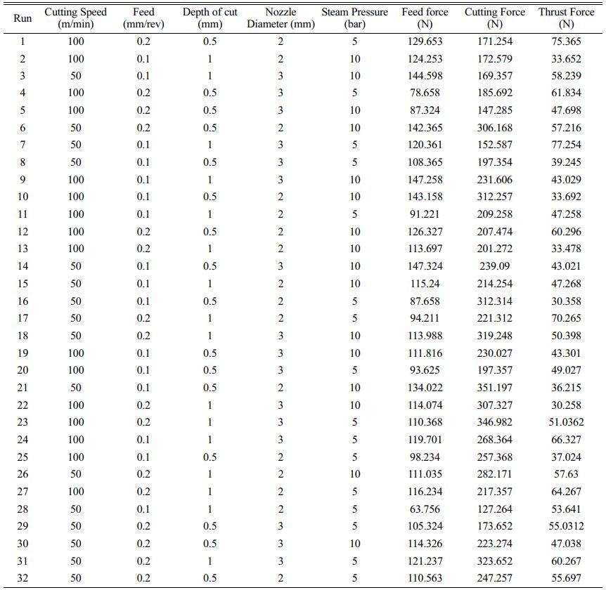
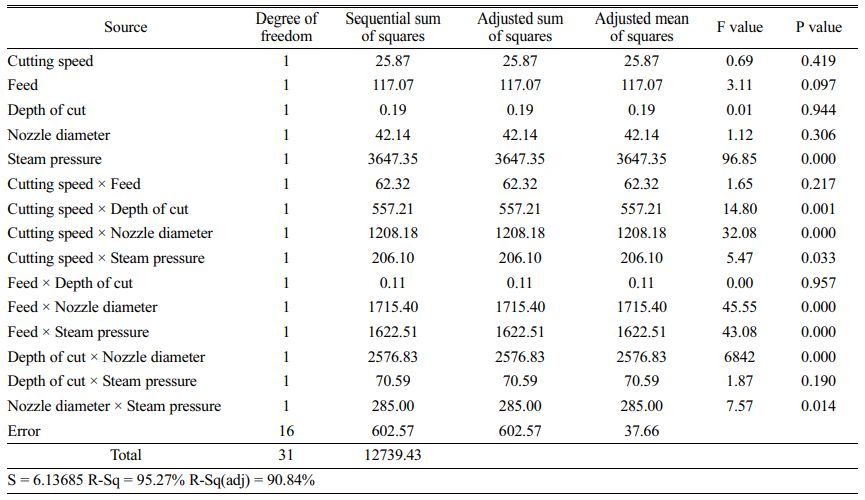
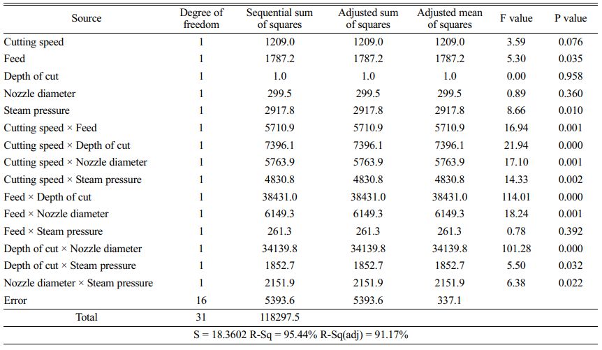
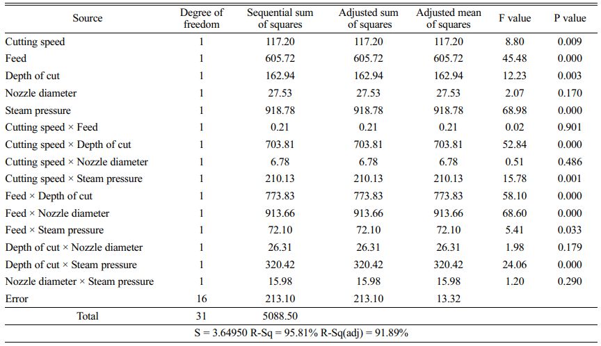
The analysis of variance (ANOVA) is used to investigate the experimental results and the parameters influencing the cutting force, feed force and thrust force in turning of aluminium metal matrix composite. (ANOVA) is used to determine whether there are any statistically significant differences between the means of two or more independent parameters. In this work ANOVA analysis is used to predict the contributions of the each process parameter in the analysis of forces during the machining of AMMC. Significance level of α=0.05 with a confidence level of 95% is used for the analysis. With this, the sources with p-value less than 0.05 are considered to be highly significant and other parameters are summarily considered as insignificant. The examination of the ANOVA table shows that the steam pressure contributes maximum and it influences the cutting force, feed force and thrust force to a major extent, whereas the other parameters are in significant and their contribution are considered to be very less. The analysis of variance for the feed force is shown in Table 2, the analysis of variance for the cutting force and thrust force are given in Table 3 and Table 4 respectively.
The Thrust force, feed force and cutting force are highly influenced by the steam pressure in the analysis of the machining of Aluminium metal matrix composite. Steam is cheap, pollution-free and eco-friendly, and then is a good and economical coolant and lubricant. Steam generator and steam feeding system were developed to generate and feed steam. The steam pressure gives a jet t flow which directly influences lubricating and cooling effect of the turning process.
Taguchi Analysis
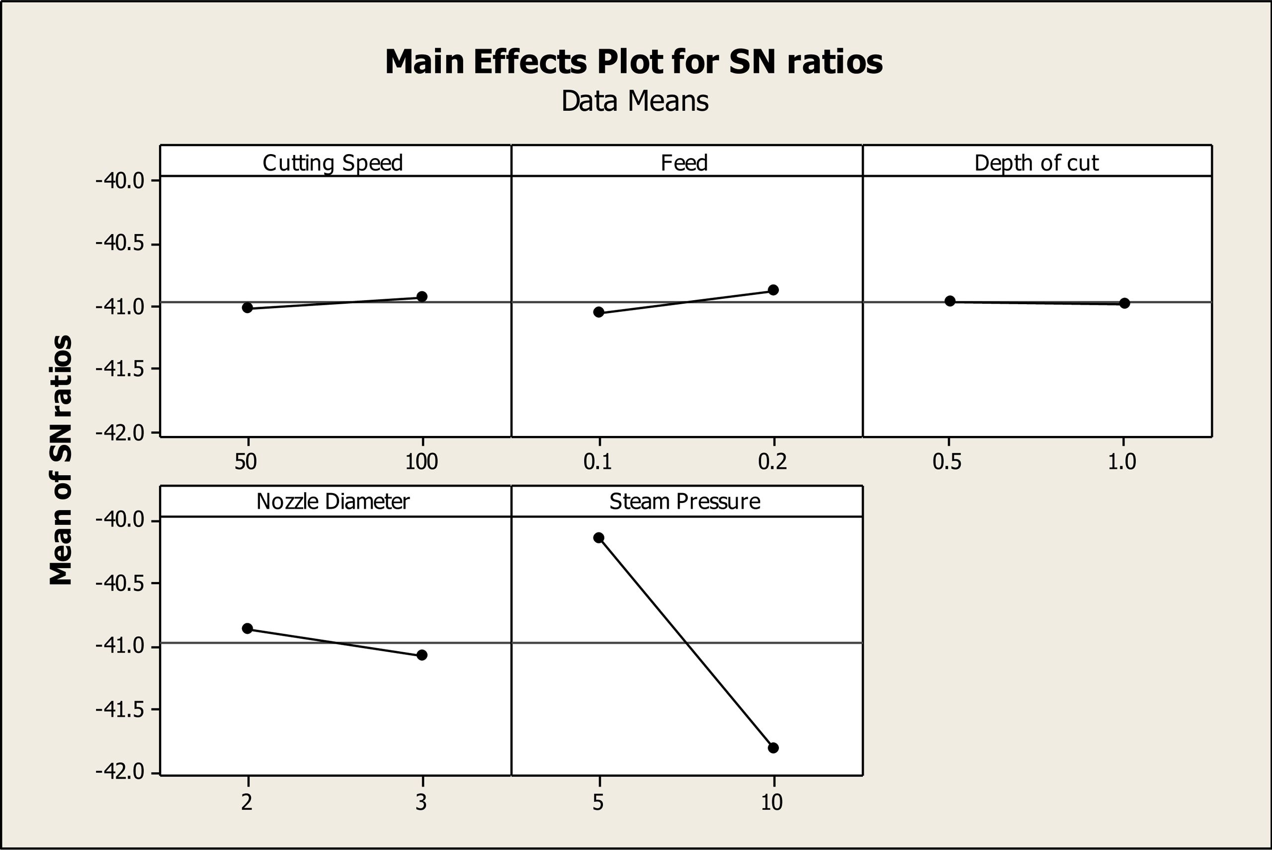
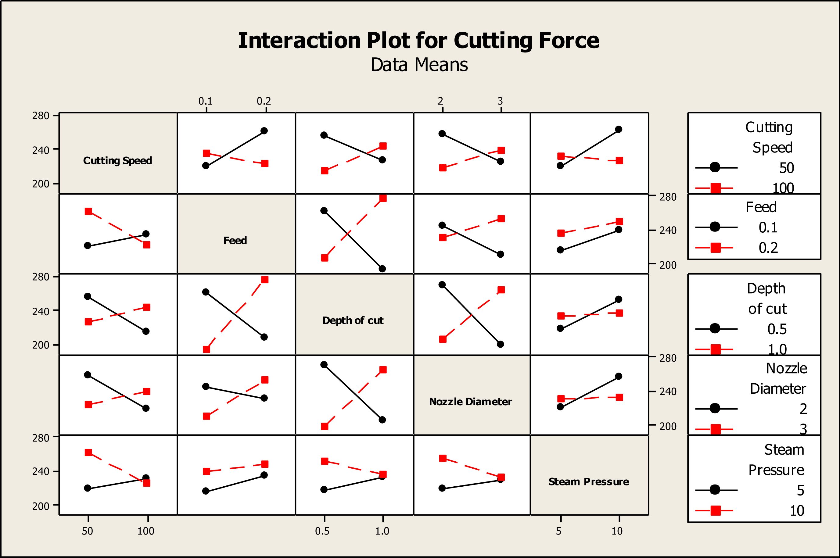
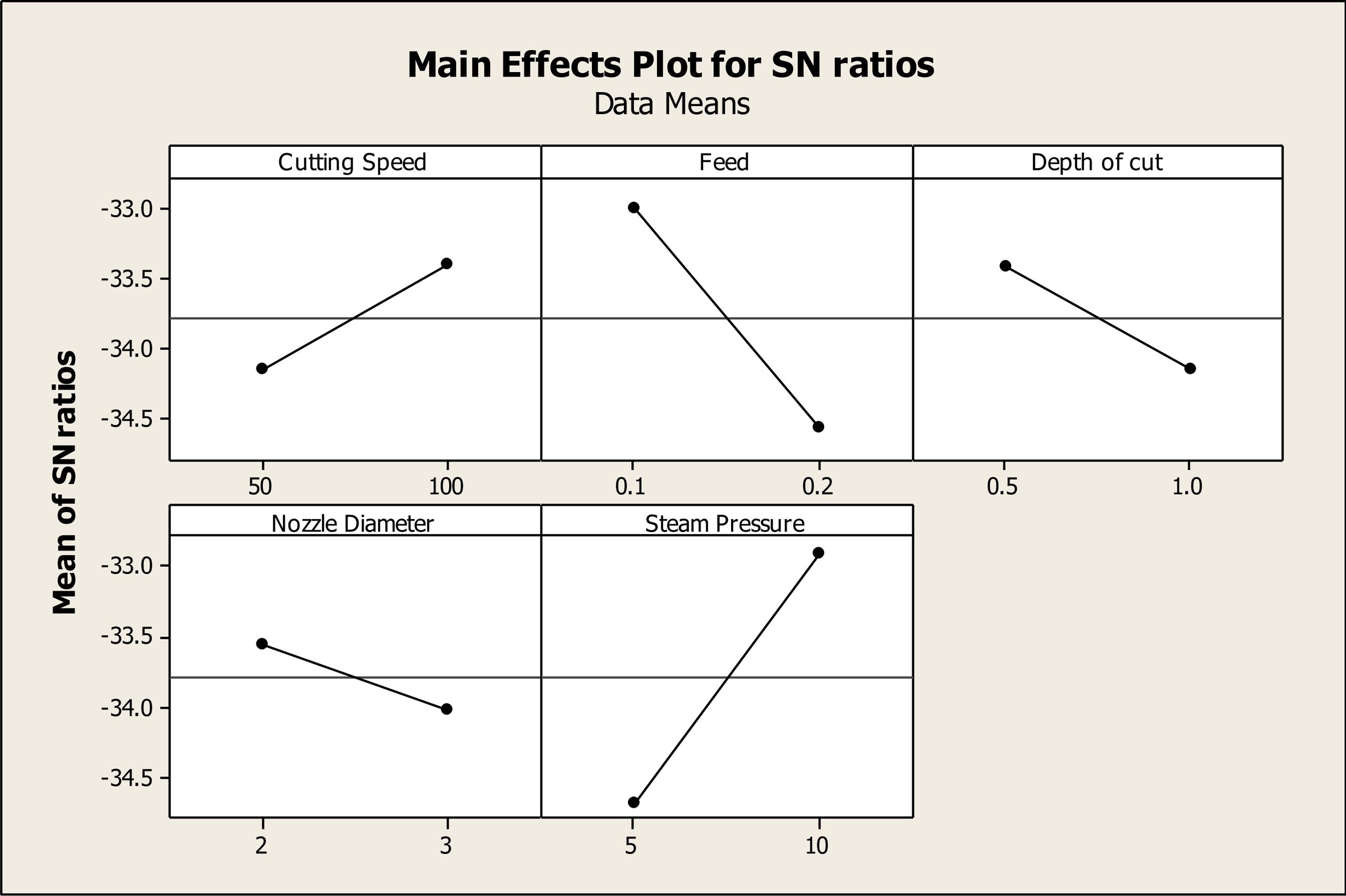
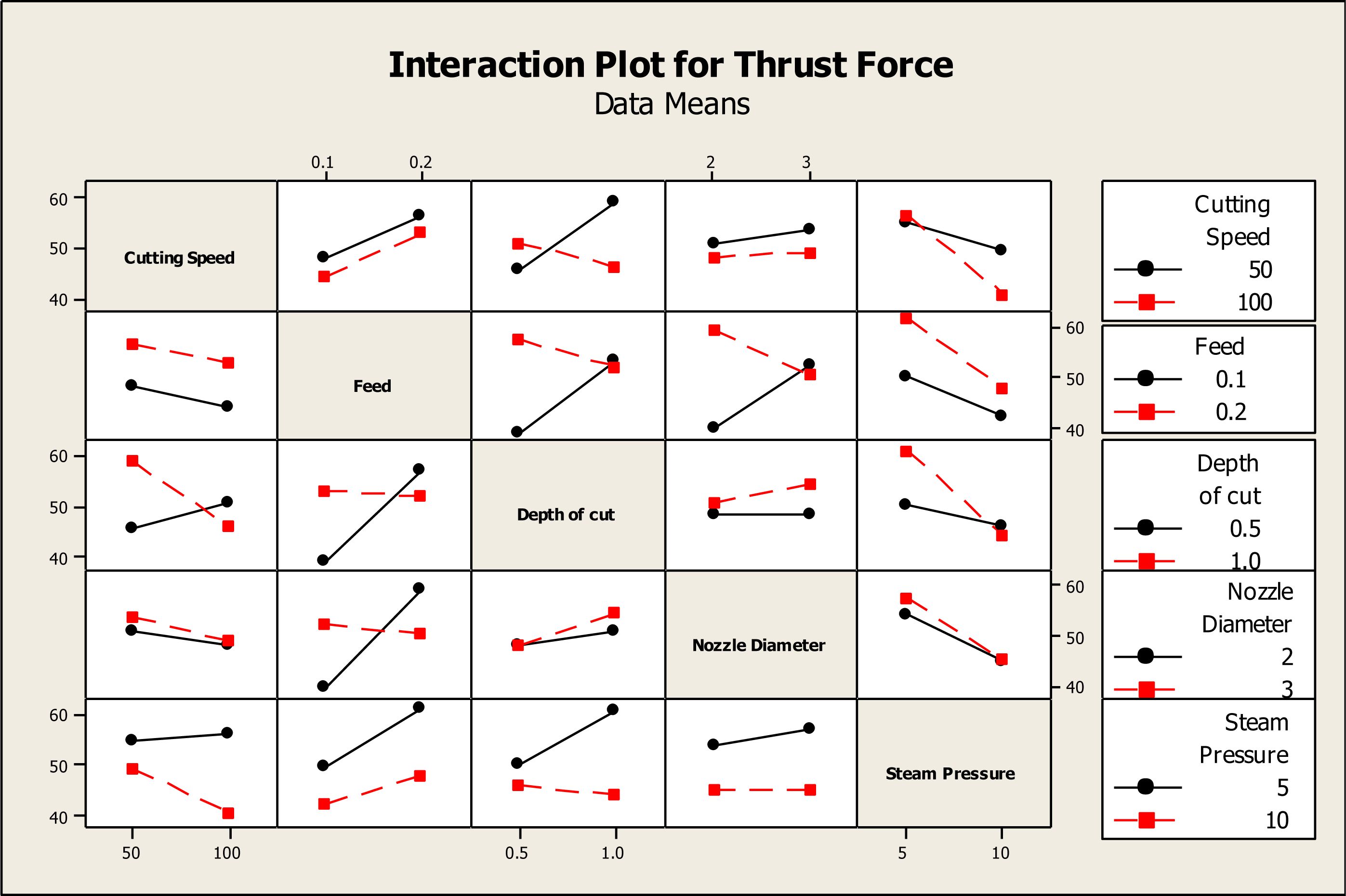
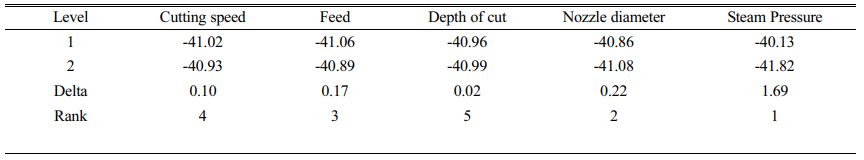
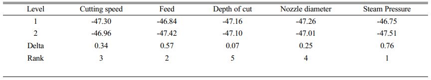
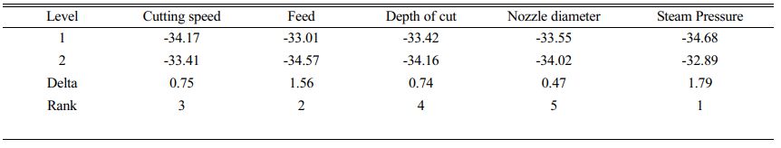
The Taguchi analysis is carried out and the signal to noise ratios are determined for these forces. Smaller the better in Taguchi analysis is taken into consideration since less amount of cutting force will provide lesser amount of tool wear. The response table for the feed force is presented in Table 5 and it is found that the steam pressure contributes to a major extent and it is followed by nozzle diameter, feed cutting speed and depth of cut. Similarly the response table for the cutting force is calculated as shown in Table 6 and it is found that the steam pressure contributes maximum and it is followed by feed rate, cutting speed and depth of cut. Similarly the response table for the thrust process is also determined using the signal to noise ratio as shown in Table 7 and it is found that the steam pressure is ranked first and it is followed by feed rate, cutting speed, depth of cut and nozzle diameter. The main effects plot and interaction plots for feed force, cutting force and Thrust force are plotted as shown in the Figs. 1-6. Fig. 2 Fig. 3 Fig. 4 Fig. 5
|
Fig. 1 Main effects plots for SN ratios for Feed force. |
|
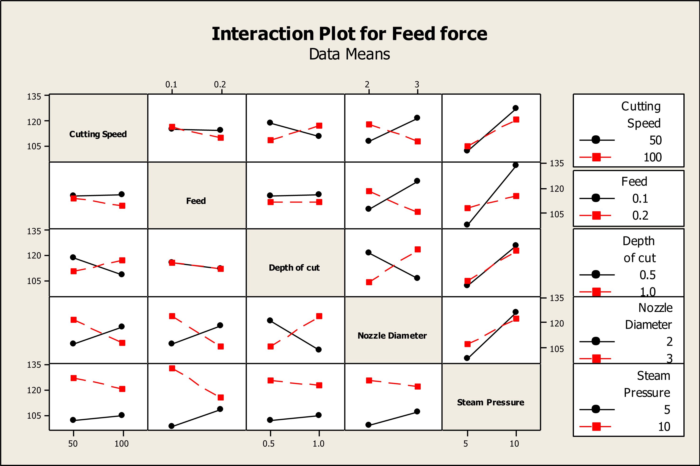
Fig. 2 Interaction plot for Feed force. |
|
Fig. 3 Interaction plot for Feed force. |
|
Fig. 4 Interaction plot for cutting force. |
|
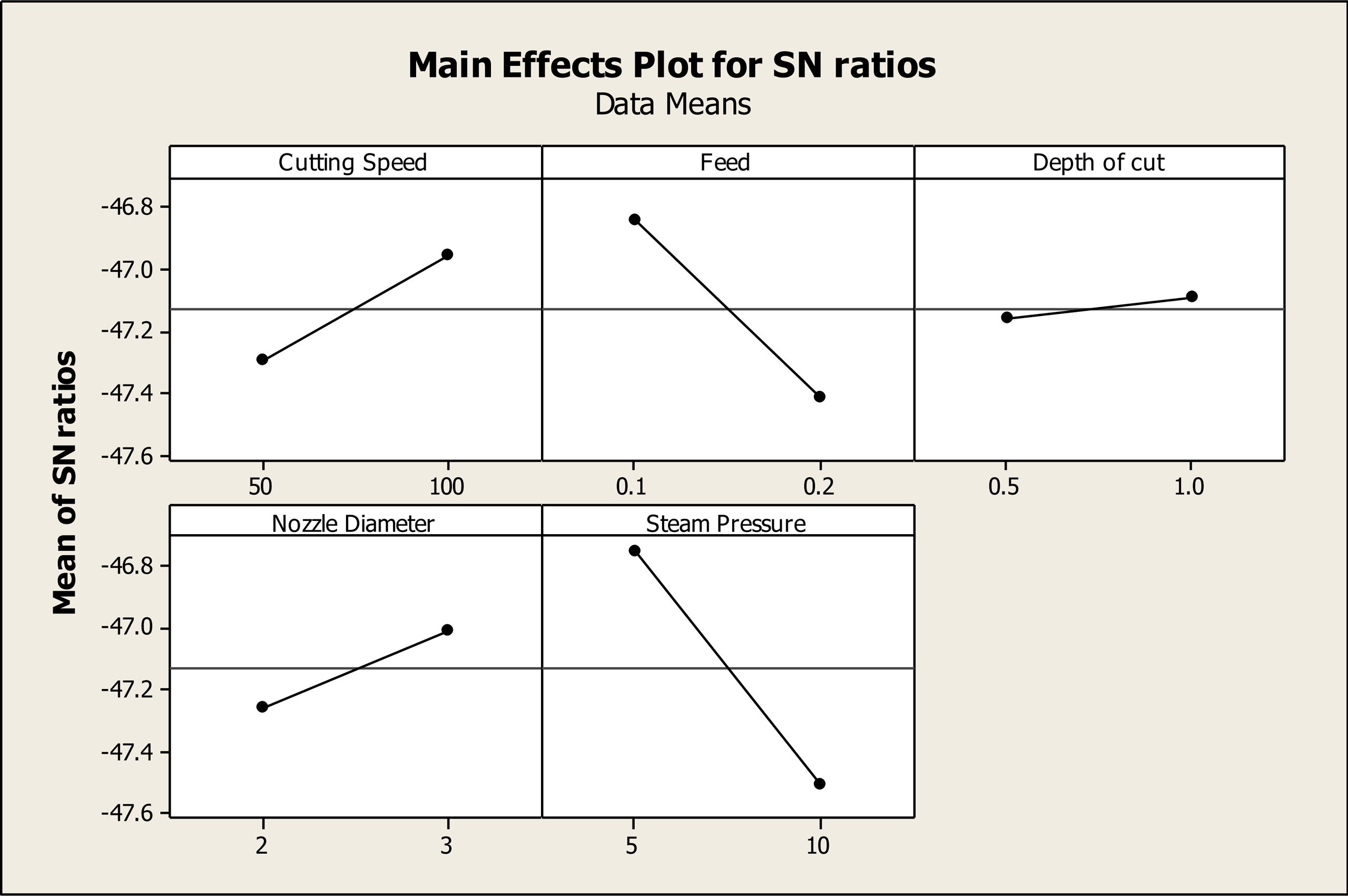
Fig. 5 Main effects plot for Thrust force |
|
Fig. 6 Interaction plot for Thrust force. |
In this work, stir casting process is employed and the specimens are prepared in the cylindrical form and the turning process is carried. The process parameters considered are cutting speed, feed, depth of cut, nozzle diameter and steam pressure. The cutting force, feed force and thrust force are considered as the responses. Taguchi analysis is carried to minimize the cutting force, feed force and Thrust force. It is found that the most influencing parameter in the optimization of cutting force, feed force and thrust force is the steam pressure. The response tables are discussed and the main effects and interactions plots are plotted and discussed.
- 1. J. Kim, L.Zani, A. Abdul-Kadir, L. Jones, A. Roy, L. Zhao, and V.V. Silberschmidt, Manuf. Lett. 32 (2022) 63-66.
-

- 2. N.H. Ononiwu, E.T. Akinlabi, and C.G. Ozoegwu, Mater. Today: Proc. 44 (2021) 1124-1129.
-
- 3. V.V. Bhandarkar, B. Pal, and S.P. Shanmuganathan, IOP Conf. Ser.: Mater. Sci. Eng. 1013[1] (2021) 012022.
-
- 4. Y. Sesharao, T. Sathish, K. Palani, A. Merneedi, M.V. De Poures, and T. Maridurai, Adv. Mater. Sci. Eng. (2021) 1609769.
-
- 5. A. Kannan, R. Mohan, R. Viswanathan, and N. Sivashankar, J. Mater. Res. Technol. 9[6] (2020) 16529-16540.
-
- 6. C.P. Rao, M.S. Bhagyashekar, P. Chandra, and D.V. Ravikumar, Mater. Today: Proc. 5[11] (2018) 24770-24779.
-
- 7. K.S. Kumar and R.N. Marigoudar, J. Mech. Behav. Mater. 28[1] (2019) 146-152.
-
- 8. R. Vinayagamoorthy, I.V. Manoj, G. Narendra Kumar, I. Sai Chand, G.V. Sai Charan Kumar, and K. Suneel Kumar, J. Mech. Sci. Technol. 32[5] (2018) 2011-2020.
-
- 9. M.P. Jenarthanan and R. Jeyapaul, Int. J. Eng. Sci. Technol. 5[4] (2013) 22-36.
-
- 10. KM. Senthilkumar, R. Thirumalai, M. Seenivasan, and T. Venugopal, J. Ceram. Process. Res. 22[6] (2021) 731-738.
-
- 11. R. Shetty, P. Pai, V. Kamath, and S.S. Rao, J. Zhejiang Univ-Sc A. 9[9] (2008) 1245-1250.
-
- 12. Mukesh Kumar, S.K. Tamang, Dipika Devi, M. Dabi, K. K. Prasad, and R. Thirumalai, J. Ceram. Process. Res. 23[3] (2022) 373-382.
-
- 13. M. Sivaperumal, R. Thirumalai, S. Kannan, and K.S.S. Yarrapragada Rao, J. Ceram. Process. Res. 23[3] (2022) 404-408.
-
- 14. R. Thirumalai, S. Karthick, and M. Giriraj, J. Ceram. Process. Res. 23[2] (2022) 221-227.
-
 This Article
-
2023; 24(1): 174-181
Published on Feb 28, 2023
- 10.36410/jcpr.2023.24.1.174
- Received on Sep 9, 2022
- Revised on Oct 3, 2022
- Accepted on Nov 19, 2022
Services
Shared
Correspondence to
- R. Santhanakrishnan
-
Department of Mechanical Engineering, CMR University, Bengaluru, India
Tel : +91 9944186041 - E-mail: sanskrish@gmail.com
Clean-Energy Research Institute(CRI), Hanyang University, 222, Wangsimni-ro, Seongdong-gu, Seoul, 04763, Korea
E-mail: jcpr@hanyang.ac.kr