


- Simulation of spreading and retraction behavior of water droplet on micro-patterned surfaces with VOF coupled level-set model
Ning Guan*, Xiang Gao, Feng Chen and Qiankun Zhu
Shandong Jiaotong University, No. 5001, Haitang Road, Changqing District, Jinan 250357, China
This article is an open access article distributed under the terms of the Creative Commons Attribution Non-Commercial License (http://creativecommons.org/licenses/by-nc/4.0) which permits unrestricted non-commercial use, distribution, and reproduction in any medium, provided the original work is properly cited.
For the anti-icing technology of hydrophobic coating on turbine blades, the influence of the hydrophobic surface with micropatterns on the impact characteristics of water droplets is studied in present manuscript. The spreading and retraction characteristics of water droplets with diameters of 2~10 μm on micro-structured surface is numerically investigated in present research by volume of fluid (VOF) and Level-set coupling method, and the influence of surface micropattern geometry and water droplet diameter on the spreading and retraction process is analyzed in detail. It is found that the ratio of water droplet diameter D0 to micropattern size P has a significant effect on the dynamic process and final shape of the impact on the same micropatterned wall; and the surface shows obvious hydrophobicity when the ratio of water droplet diameter D0 to micropattern size P is 2 ≤ D0/P ≤ 4 and the movement of water droplets on the surface is in accordance with the description of the Cassie model, although the contact angle of substrate material is 86°. However, the dynamic process and final shape of water droplets are similar to those on a smooth plane with the contact angle of 86° when D0/P ≤ 1. In addition, when the water droplet impacts the micropatterned surface with 2 ≤ D0/P ≤ 4, the spreading coefficient on the micropattern surface is less than 1.0 and the dimensionless spreading period gradually lengthens with the increase of D0/P value attributed to the large pressure gradient near the three-phase line
Keywords: Spreading and retraction, Water droplets, Micropattern, Hydrophobic surface, Wind power engineering, VOF computational model.
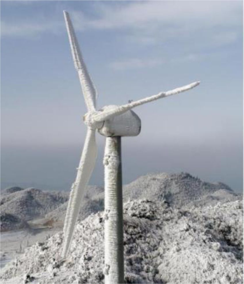
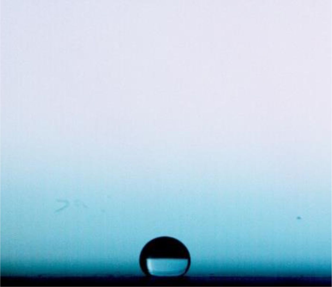
In wind power complex systems at high altitudes or in frigid regions, the surface of the blades is prone to ice formation, as shown in Figure 1. Under moderate and severe icing meteorological conditions, the power loss of wind turbines due to icing accounts for 5% to 25% of the total annual power generation [1-4], which seriously affects the power generation efficiency of wind turbines. At the same time, it will also cause the failure of the wind speed and direction indicator [5], and even cause damage to the mechanical mechanism of the blade [6]. Therefore, the anti-icing problem of wind turbine blades has become one of the research focuses of the wind power engineering. By applying a hydrophobic or superhydrophobic coating on the wind blade to make the blade surface a hydrophobic surface as shown in Fig. 2, the adhesion time of water droplets on the blade can be shortened [7], thereby preventing ice coating on the surface of the wind blade. Therefore, it is of great significance to study the impact characteristics of water droplets on hydrophobic surfaces, especially the spreading and retraction characteristics of water droplets, for the study of the icing phenomenon of wind turbine blades.
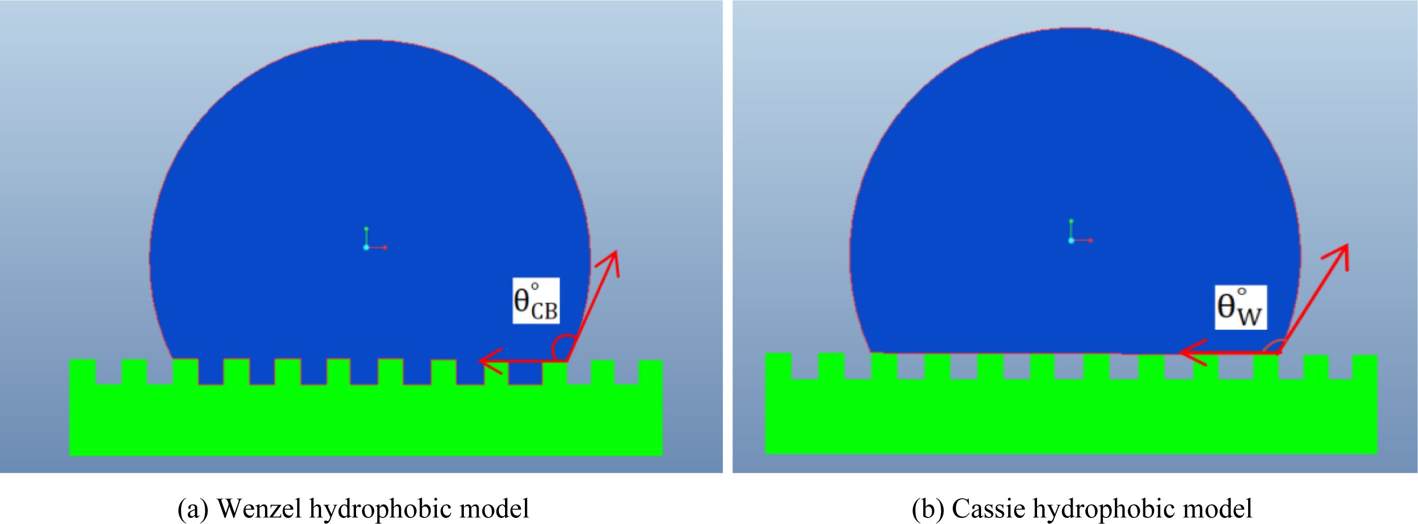
When a water droplet impacts the solid surface at a certain speed, dynamic phenomena such as spreading, retraction and bouncing will occur, and the appearance and characteristics of these phenomena are related to the diameter and speed of the droplet as well as wetting characteristics of the contact surface. When the contact surface has obvious hydrophobicity, such as lotus leaves and cicada wings in nature, the droplets will retract to nearly circular shape after spreading, so, compared with hydrophilic surfaces like metal surfaces, the solid-liquid contact area of droplets on hydrophobic surfaces is significantly reduced, which are often applied in self-cleaning [8-12], flow resistance reduction [13-16] and ice/frost prevention [17, 18] to conserve energy. For the above-mentioned bouncing characteristics of droplets on hydrophobic surfaces, [19] and [20] respectively pointed out that the reason lies in the presence of a large number of micropatterns on hydrophobic surfaces, as shown in Fig. 3, and the three-phase contact characteristics among micropatterns, droplets and air are the key factors that determine the bouncing characteristics and contact angles of droplets on surfaces.
With the continuous development of hydrophobic materials, the hydrophobicity of icing surfaces can be achieved by coating with fluorosilanes or nanocoatings. In a previous study, the authors obtained surface contact angles over 150 degrees by coating fluorosilane-based coatings on icing surfaces. Electron microscope photographs of the surface showed a large number of microstructuFires ranging from a few hundred nanometers to several micrometers on the surface [21], and the microscopic characterization being consistent with the hydrophobic model proposed by M. Suwan and S. Supothina [22] fabricated optically transparent poly(methyl methacrylate) (PMMA)/SiO2 nanocomposite superhydrophobic films by a dip coating method for a small piece of specimen, and a spray-on coating method for a large specimen such as a glass panel, the dip-coated film exhibited water contact angle (WCA) of 160.4°. H. I. Hsianga et al. [23] coated a perfluroalkyl surfactant (perflurodecanoic acid, PFDA) on nano-sized boehmite surfaces to obtain hydrophobic nano-particles via surface modification, and the contact angles of the thin film prepared by spin coating PFDA-modified-boehmite on glass substrates were larger than 150°.
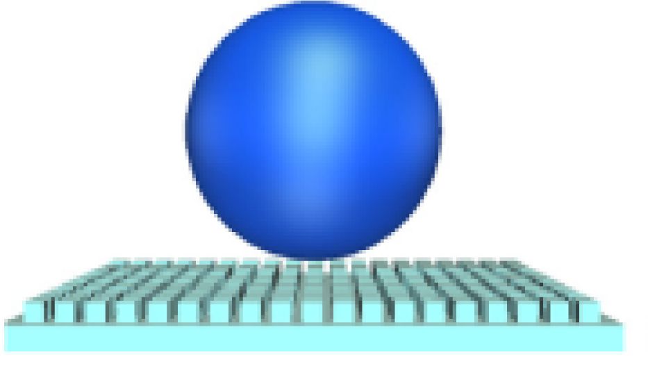
The Wenzel equation and the Cassie-Baxter equation are often utilized to describe the contact angle of droplets on hydrophobic surfaces. Based on the Wenzel and Cassie models, many scholars have built surfaces with micropatterns as shown in Fig. 4, and simulated the spreading and retraction of water droplet impacting on this kind of surface through experimental or numerical methods.
Z. Yuan et al. [25, 26] carried out numerically studies on the directional rebound behavior of liquid water droplets on hydrophobic surfaces with micro-grooves, and the results showed that there were three kinds of droplet rebound and the rotating behavior, and these behaviors were affected by the combined effects of the unbalanced Young’s force, the wetting state, the Weber number (We), and structural dimensions of grooves. Besides, Z. Yuan et al. [26, 27] also proposed a three-dimensional numerical simulation method to simulate the impingement of droplets on textured surfaces with primary structures. In addition, N. Samkhaniani et al. [28] researched the hydrodynamics and heat transfer of the water droplet impinging on a heated hydrophobic surface, and a new correlation with contact time was noted based on comprehensive simulation. Furthermore, two different movements of droplets on a micropatterned surface were explored by J. Zhao and S. Chen [29] through a many-body dissipative particle dynamics method, and it was found that the migration trajectory of the droplet was related to the impact velocity, the height of micro-pillar, and the surface tension.
The dynamic behavior of water droplets on hydrophobic surfaces was also experimentally studied. Dong Song et al. [30] carried out experimental research on the wetting states of water droplets on partially micro-grooved surfaces, and found that the contact angle along the direction parallel to grooves was larger than that on the smooth surface, while the micropattern had little effect on the contact angle along the direction perpendicular to the grooves. Additionally, J. B. Lee et al. [31] investigated the influence of the texture area fraction and drop impact velocity on the spreading characteristics of water droplet, and proposed a modified equation to predict the maximum spreading factor by involving various texturing effects and wetting states. H. Wang et al. [32] carried out experimental research to investigate the bouncing characteristics of a water droplet on SHS (super-hydrophobic surface) with large temperature difference, and an increase in the droplet-SHS contact time or a decrease in rebounding height was observed by lowering the SHS temperature or by increasing the droplet temperature or droplet diameter. Moreover, the movement characteristic of droplets on unidirectional channels was investigated by H. Wu et al. [33], and droplet metering, merging or reaction, and rapid transport was observed by integrating the idea of gradient wettability patterns into planar microfluidic devices in a self-driven fluid transport. Ding et al. [34] experimentally studied the effect of superhydrophobic surface inclinations and themdegree of supercooling on water droplet dynamics, and the different rebound behaviors were observed with the decrease of the surface temperature when a liquid droplet of 14 μL impacted to a superhydrophobic surface with static contact angle of 160 ± 1° at velocity of 0.99 m·s-1.
It is known from the above research that although amounts of literature constructed micropatterned surfaces to numerically simulate hydrophobic surfaces according to the theory of Wenzel and Cassie, a large contact angle is always set on the solid-liquid contact surface in the numerical simulation, so the hydrophobic motion characteristics obtained from the study cannot reflect the role of the micropattern in the hydrophobic dynamic motion of the water droplets.
To address above problems, the present research establishes models of micropatterned surfaces with different sizes but at the same contact angle of 86° to investigate the effect of micropattern size and droplet diameter on the spreading and retraction of droplet impact, and possible conditions for the emergence of hydrophobic motion characteristics on micropattern surfaces are discussed by multiphase flow section interface tracking (VOF and Level-set coupling) method.
|
Fig. 1 Ice accretion on a wind turbine |
|
Fig. 2 Photo of water droplets on a hydrophobic surface |
|
Fig. 3 Hydrophobic models. |
|
Fig. 4 Hydrophobic surface model with micropatterns [24] |
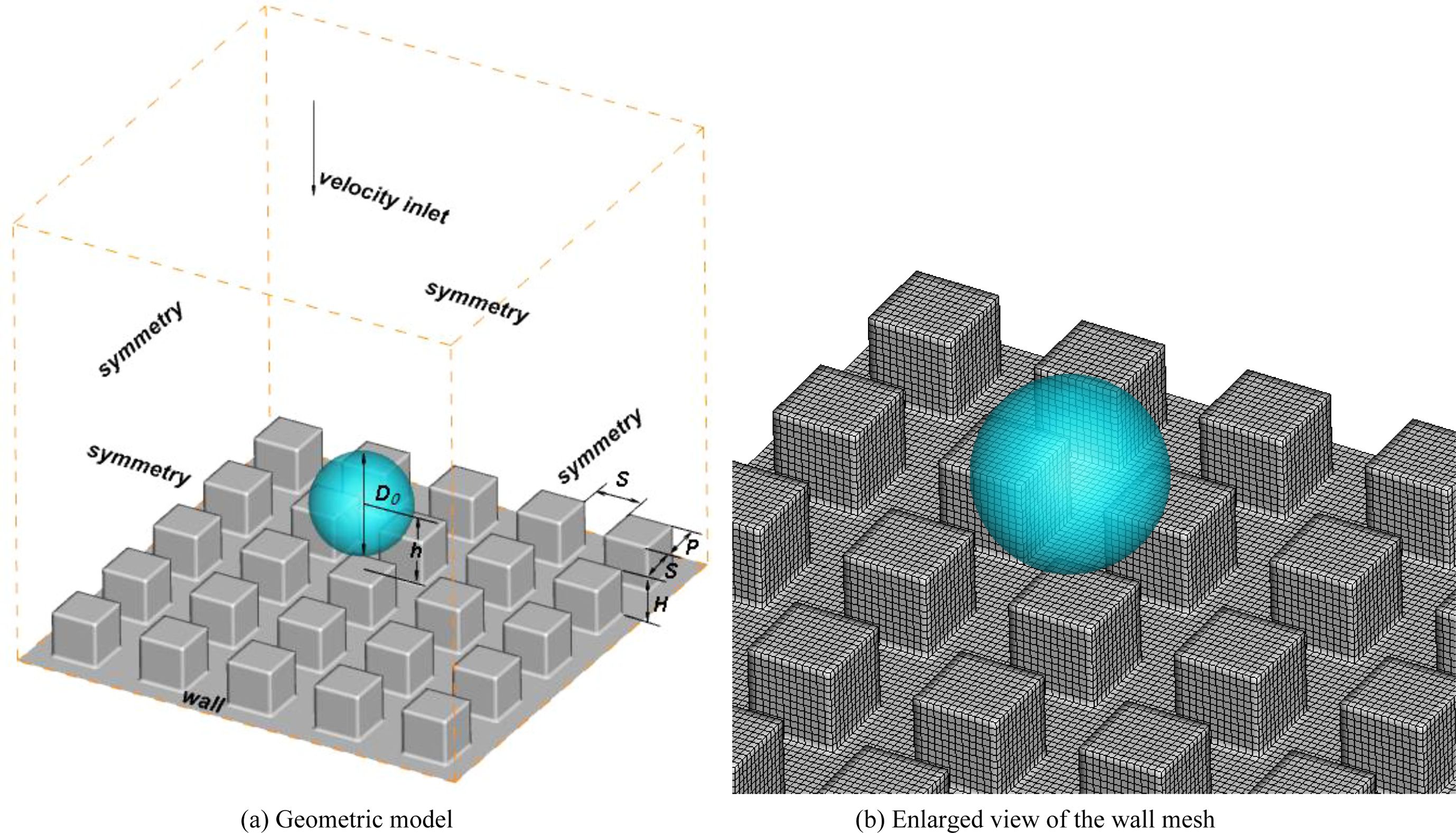
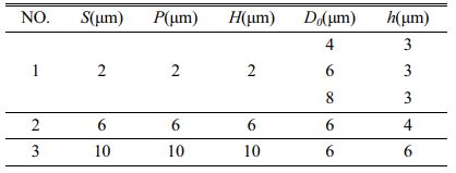
According to the Cassie model, a geometric model with different micropattern sizes is established in this paper as shown in Fig. 5, and the micropattern sizes, water droplet diameters and drop locations of each surface are listed in Table 1. The structured mesh is generated for each model in Table 1 and the number of grids was 518400, 1276400 and 1713600, respectively. The mesh independence is validated by comparing spreading area of the water droplet at the same time point and the discrepancy is not more than 3%, so the mesh with the number of 1276400 is taken as the calculation mesh in the numerical investigations below.
Based on the above geometric model and mesh, the VOF method combined with Level-set interface tracking method is used to simulate the impact motion of micro-water-droplet on the micropatterned surface. According to the continuity equation, the volume fraction of liquid water in each computational cell can be solved by the following equation:
The volume fraction of air can be obtained from 1-αw. In the VOF method, the phase interface is constructed by a piecewise linear function, and in order to avoid the discontinuity problem that may be caused by this, thus improving the tracking accuracy of the interface direction and curvature, this model introduces a level-set higher-order function φ to calculate the interface curvature.
The controlling equation of the function φ(x,t) is shown as below:
Then the normal vector of the interface n and the curvature of the interface κ can be calculated by the following formulas:
The momentum equation of the flow field is shown in the following equation.
In the above equation, FSF is the surface tension source term. And in this paper, the surface is assumed to be smooth aluminum base with a surface contact angle of 86° to explore the effect of micropattern on the dynamic motion and bouncing characteristics of water droplets. Besides, the density ρ and the dynamic viscosity μ are taken as the average volume of air and liquid water, respectively. Here, the surface tension coefficient is set as 0.073 n/m.
The impact motions of the water droplet on the surfaces listed in Table 1 are calculated basing the mesh shown in Fig. 5. In addition, the boundary conditions of the numerical simulation are depicted in Fig. 5(a), and values of parameters P, S, H, h and D0 can be found in Table 1.
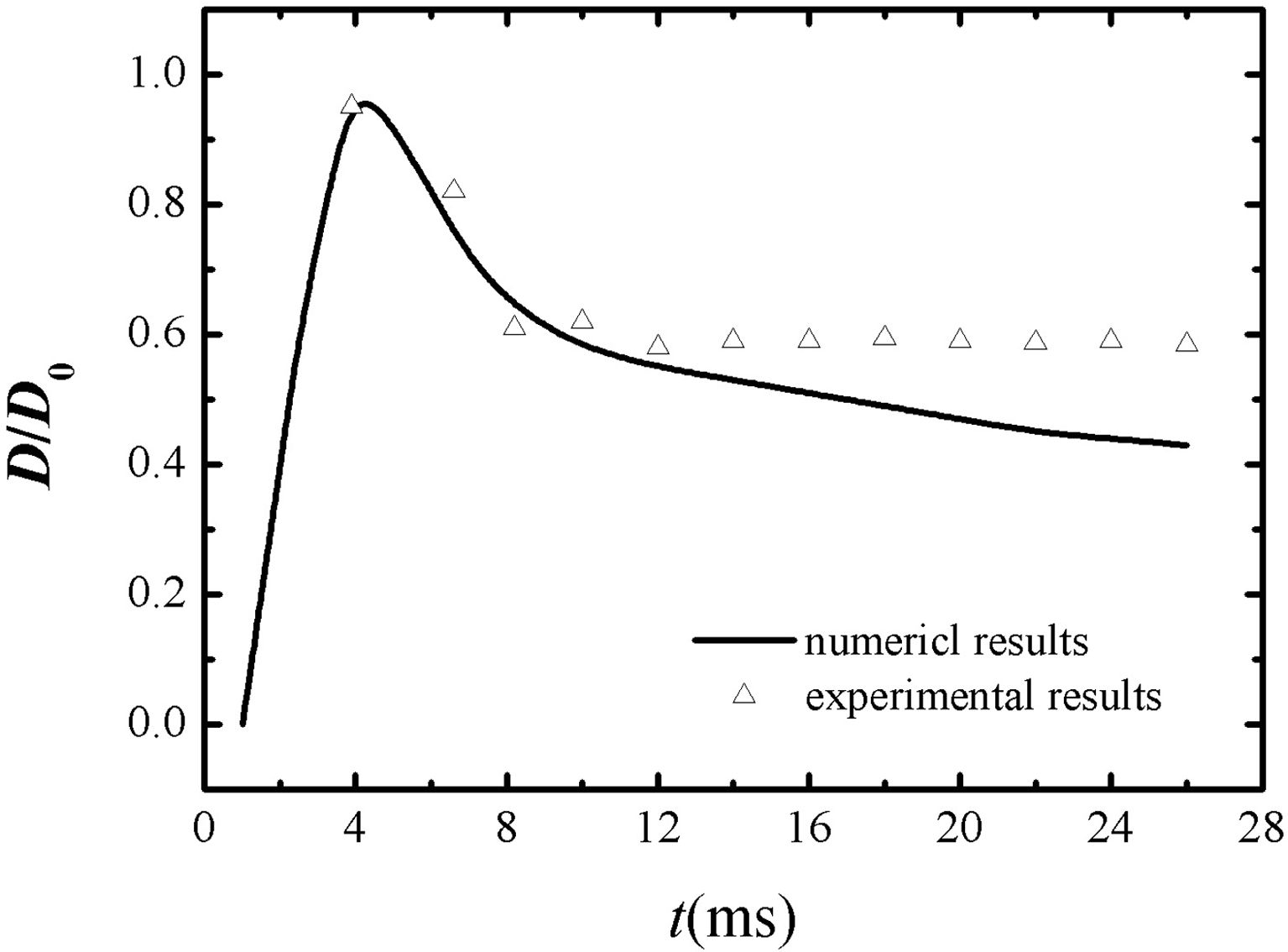
In order to verify the above model, the numerical results obtained by the model presented in this manuscript are compared with the experimental results measured by high speed camera system (PCO12000hs, Germany), as shown in Fig. 6. Through comparison, it can be found that the calculated results of the model in this paper agree well with the experimental results, especially at the early stage of spreading and retraction, the spreading coefficients obtained from numerical simulation match with the experimental data.
|
Fig. 5 The geometric model and wall mesh depiction. |
|
Fig. 6 Comparisons between the numerical results and the experimental results. |
Figs. 7~9 illustrate the morphological changes of water droplets with the diameters D0 of 4 μm, 6 μm and 8 μm, respectively, with an initial velocity of 0.25 m/s.
In this paper, the minimum size of the computational cell is as small as 0.17 μm to prevent water droplets from deforming, so the time step needs to be less than 2e-8s in order to ensure that the courant number does not exceed 0.25. For the purpose of saving the computational time, the falling positions of the three different water droplets are set to the position where the lowest point of the water droplet boundary is 1 μm above the wall, i.e., the distance between the centre of the water droplet and the wall is h=4 μm, 6 μm and 8 μm respectively for the droplets with different diameters, and thus the time when the droplet began to contact the wall is different due to height difference. As shown in Figs. 7(a), 8(a) and 9(a), the time point is 2.2 μs, 3.35 μs and 7.8 μs separately when the droplets begin to impact the wall, and there is obvious spreading phenomenon and retraction phenomenon at 0.04 μs and 0.08 μs after the impact, as shown in Figs. 7 (d) and 7(e). After several times of spreading and retractions, the water droplets basically maintain the shape, as shown in Fig. 7(f). Besides, compared with the water droplets with D0=4 μm, the appearance time of the spreading phenomenon of the water droplets with D0=6 μm and 8 μm is obviously delayed, and appeared until 0.07 μs and 2.08 μs after the start of impact, respectively. Moreover, the period from spreading to retraction is obviously extended, as shown in Figs. 8-9, the durations of time from spreading to retraction for D=6 μm and 8 μm water droplets are 0.11 μs and 2.92 μs, respectively.
Furthermore, it can be seen from Figs. 7~9 that when the water droplets impact on the surface with micropatterns of 86° contact angle, the droplets did not spread into a semicircle, but remained nearly circular, i.e., they showed a better hydrophobicity. In addition, the dynamic motion and the final shape of the water droplets are related to the micropattern size, and by comparing Figs. 7(f), 8(f) and 9(f), the conclusion can be drawn that the final morphology of the water droplets is closer to a circle as their diameter increases.
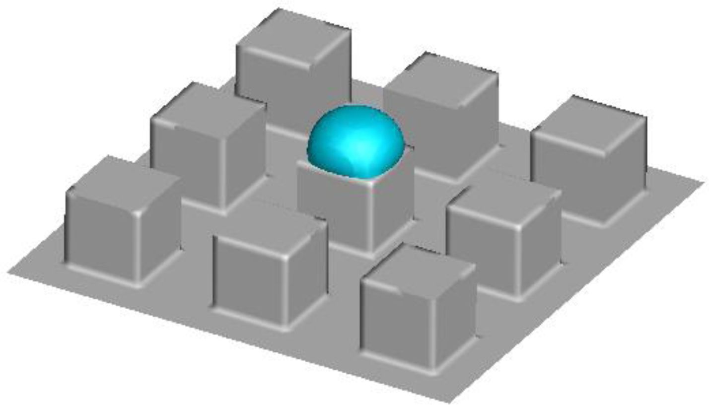
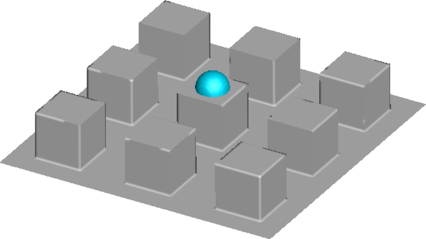
It can be found from the above analysis that when the wall has the same micropatterns, the water droplet diameter has a significant effect on the dynamic motion and final shape of the droplet. To further analyze the effect of micropattern on the water droplet impact characteristics, the final water droplet morphologies after the water droplet with D0=6 μm impacts the NO.2 and NO.3 surfaces in Table 1 are presented in Figs. 10~11, respectively. The comparison among Figs. 10~11 shows that with the increase of micropattern size, the influence of micropattern on water droplet morphology gradually disappears, and the final shape of water droplet gradually approaches to the spreading state of water droplet on the smooth surface with the same contact angle. The comparison of Figs. 7~11 reveals that the dynamic motion and final shape of water droplets impacting the micropatterned surface are related to not only the droplet diameter but also the micropattern size: when D0/P ≥ 2, the micropatterned surface shows obvious hydrophobicity; when D0/P ≤ 1, the dynamic process and final shape of water droplets are similar to those impacting the smooth surface with the same contact angle.
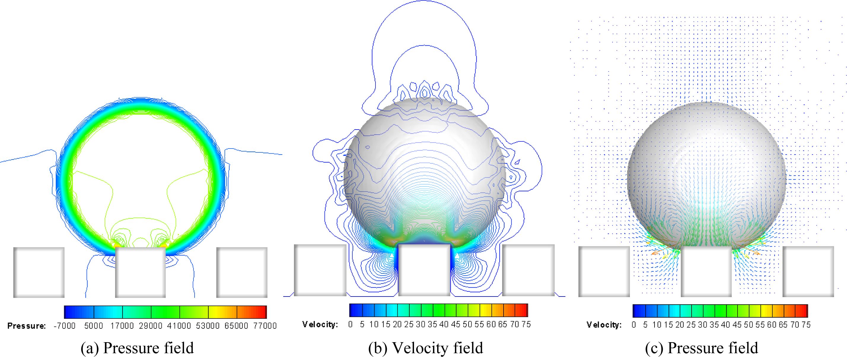
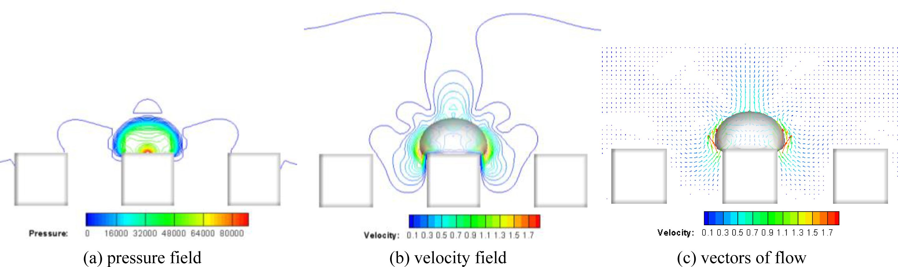
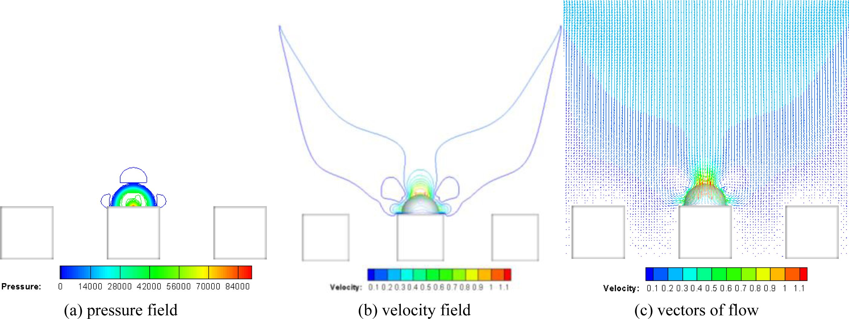
As mentioned above, the droplet diameter and the size of the micropattern have obvious effects on the droplet impact process and the final morphology. To explore the mechanism of these effects, the pressure field, velocity field and velocity vector distributions after the droplet with D0=6 μm impacts on the micropatterned surfaces of S=2 μm, 6 μm and 8 μm and coming into the steady state are presented in Figs. 12~14, respectively. Comparing Figs. 12(a), 13(a) and 14(a), it can be found that due to the presence of surface tension, significant pressure gradients appear near the contact surface of both gas-liquid phases. Meanwhile, when P=6 μm and 10 μm, the highest pressure point appears at the centre of the contact surface between the water droplet and the micropattern, as shown in Figs. 13(a) and 14(a); while when P=2 μm, the highest pressure point is located on the gas-liquid-solid three-phase line as shown in Fig. 12(a), i.e. This phenomenon is attributed to the differences of the surface tension near the three-phase lines on surfaces with different micropattern sizes. The pressure difference near the three-phase line is significantly higher when the micropattern size is smaller than the water droplet diameter, thus maintaining a larger contact angle of the water droplet on the micropatterned surface, as shown in Fig. 12.
In addition, the velocity field and velocity vector distributions on different micropatterned surfaces are significantly different, as presenting in Figs. 12~14. When the water droplet diameter D0 is not smaller than P, a region of elevated velocity appears near the three-phase contact line as shown in Figs. 12(b) and 13(b), while when D0 is smaller than P, the highest velocity appears at the top of the water droplet, as shown in Fig. 14(b), which may be due to a larger pressure gradient exists near the three-phase line when the droplet diameter is larger than the bump size, and generating a higher velocity air flow when the droplet shape changes.
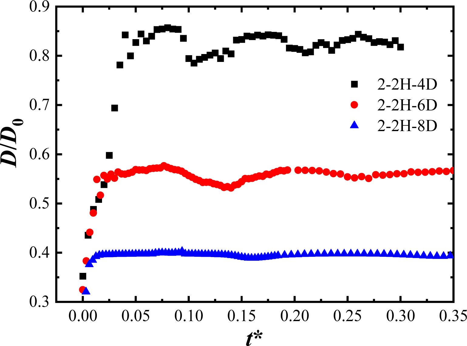
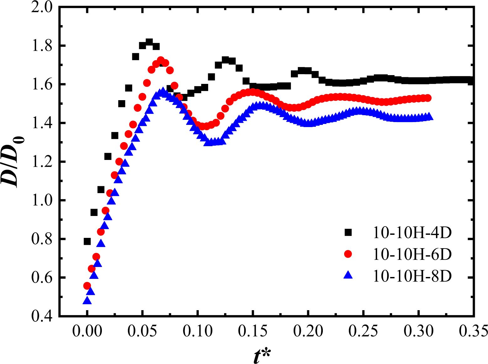
To further explore the effect of surface micropattern on the dynamic motion of droplet impact, the variation of spreading coefficient with dimensionless time t* after different diameters of droplets start to impact the micropatterned surfaces with P=2 μm and P=10 μm, respectively, are presented in Figs. 15~16. The spreading coefficient is defined as the ratio of the droplet wetting equivalent diameter D to the droplet diameter D0 at the initial moment of falling, and the dimensionless time t* is defined as follows.
Where, u0 is the initial velocity of the drop.
When the micropattern size is P=2 μm, the water droplets with D0=4, 6, and 8 μm all maintained a more complete spherical shape after a series of bounce, as shown in Figs. 7~9. Therefore, the wetting area of the water droplets on the micropatterned surface were all similar to the top area of the micropattern, so the spreading coefficient was always less than 1.0 when the water droplets started to impacting the micropatterned surface, as shown in Fig. 15. In addition, the spreading coefficients of water droplets on the micropatterned surfaces of D0=4 μm and 6 μm show more obvious periodic changes, with dimensionless periods of about 0.095 and 0.14 and maximum spreading coefficients of 0.86 and 0.58, respectively. However, the maximum spreading coefficient of the D0=8 μm water droplet is only 0.4, and the spreading period is extended to about 0.17, while the amplitude of the spreading coefficient in a single period is much smaller than that of the D0=4 μm and 6 μm water droplets.
When the micropatterned size increases to P=10 μm, the spreading coefficients of water droplets with different diameters are greater than 1.0 and slightly decrease with increasing diameter. As shown in Fig. 16, the maximum spreading coefficients are 1.82, 1.72 and 1.56 when the water droplet diameters are D0=4, 6 and 8 μm, respectively, which increase by 111.6%, 196.6% and 290% correspondingly, compared to the P=2 μm surface. The periods were about 0.068, 0.083 and 0.094, which slightly extended with increasing diameter but reduced by 28.4%, 40.7% and 44.7%, respectively compared to the P=2 μm surface. It can be seen that for the same surface substrate, when D0/P < 1, the spreading coefficient of water droplets shows a significant increase compared to that of 2 ≤ D0/P ≤ 4, while the dimensionless spreading period is shortened and no significant hydrophobic effect can be brought about by the micropatterns.
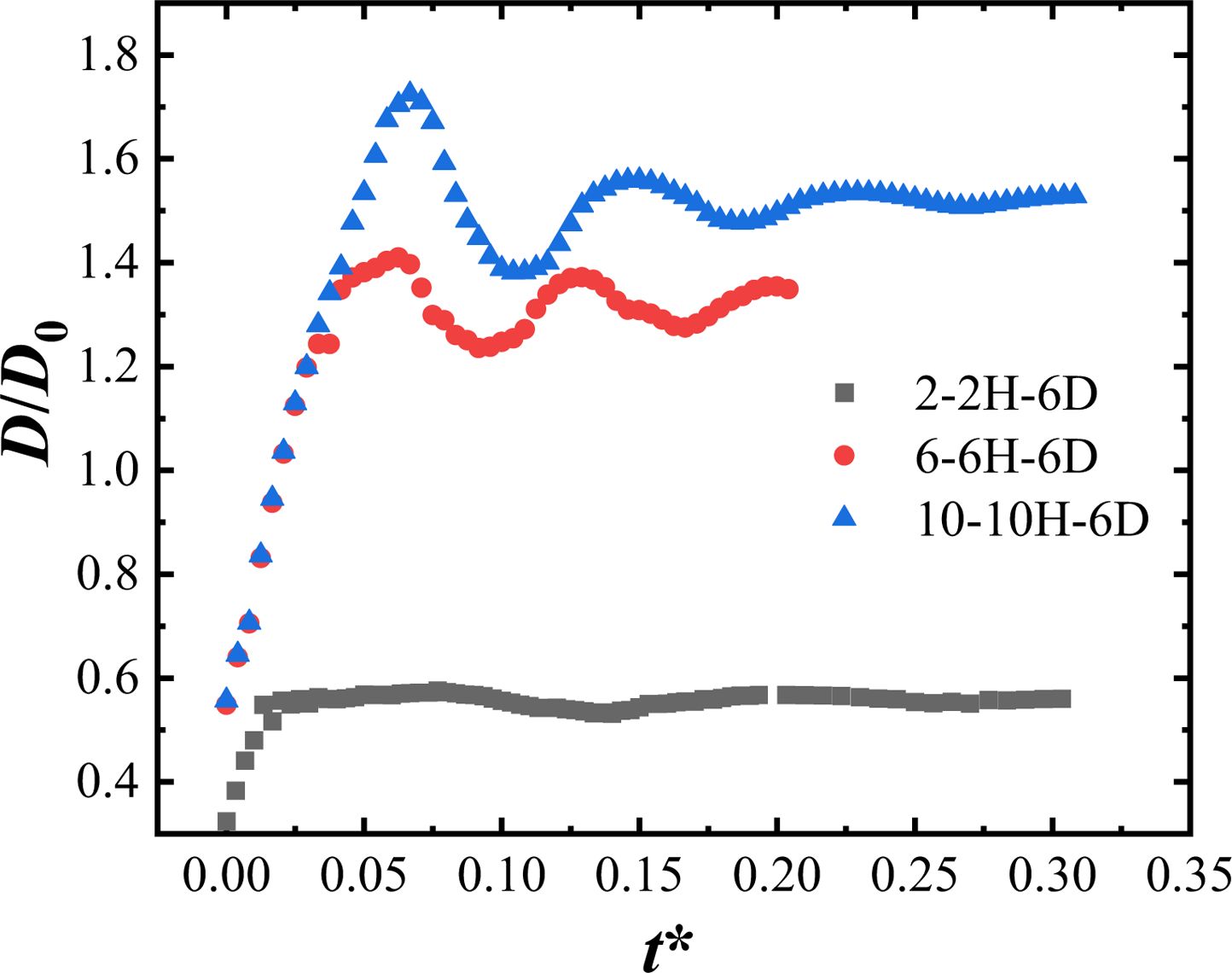
Furthermore, the variation of spreading coefficient with dimensionless time during the water droplets of D0=6 μm diameter falling with an initial velocity of v=0.25 m/s and impacting the micropatterned surfaces of P=2, 6, and 10 μm is presented in Fig. 17 to analyze the effect of surface micropattern on the spreading and retraction of water droplets. As can be seen from Fig. 17, the spreading coefficients of the water droplets are larger than 1.0 when P=10 μm and 6 μm, with maximum spreading coefficients of 1.72 and 1.41, while spreading and retraction periods is 0.083 and 0.0667, respectively. When P=2 μm, the spreading coefficient drops to below 1.0 as mentioned before, with a maximum spreading coefficient of 0.58 and an oscillation period of 0.14.
Above analysis shows that the spreading-retraction characteristics of water droplets on the micropattern not only relate to the micropattern size, but also depend on the droplet diameter. Only when the water droplet diameter is larger than the micropattern characteristic size, will the dynamic characteristics of the water droplet show more obvious hydrophobic characteristics, since its spreading coefficient and spreading period are related to the value of D0/P.
|
Fig. 7 Morphological changes of water droplet impact process on NO.1 surface of S=2 μm (v=0.25 m/s, D0=4 μm, h=4 μm) |
|
Fig. 8 Morphological changes of water droplet on NO.1 surface of S=2 μm (v=0.25 m/s, D0=6 μm, h=6 μm) |
|
Fig. 9 Morphological changes of water droplet on NO.1 surface (v=0.25 m/s, D0=8 μm, h=8 μm) |
|
Fig. 10 Final spreading pattern of water droplets on the surface with micropattern of S=6 μm, P=6 μm (v=0.25 m/s, D0=6 μm, h=6 μm) |
|
Fig. 11 Final spreading pattern of water droplets on the surface with micropattern of S=10 μm, P=10 μm (v=0.25 m/s, D0=6 μm, h=10 μm) |
|
Fig. 12 Pressure field, velocity field and velocity vectors near the water droplet with D0=6 μm on NO.1 surface in steady state. |
|
Fig. 13 Pressure field, velocity field and velocity vectors near the water droplet with D0=6 μm on NO.2 surface in steady state. |
|
Fig. 14 Pressure field, velocity field and velocity vectors near the water droplet with D0=6 μm on NO.3 surface in steady state. |
|
Fig. 15 Variation of surface spreading coefficient for different diameter droplets impacting the NO.1 surface. |
|
Fig. 16 Variation of surface spreading coefficient for different diameter droplets impacting the NO.3 surface. |
|
Fig. 17 Variation of surface spreading coefficient of D0=6 μm water droplet impacting surfaces with different sizes of micropattern. |
In this paper, the spreading and retraction characteristics of water droplets with different diameters on the surface of a non-hydrophobic substrate with micron-level patterns are investigated by utilizing VOF method, and the influence of surface micropattern size and water droplet diameter on dynamic impacting motions is analyzed. The specific research findings are as follows.
(1) Based on the VOF coupled Level-set model, the present research constructs different micro-patterned surfaces on metal substrates without pre-set large contact angles, and the influence of microstructures on the spreading and retraction characteristics of water droplets is investigated, and the results can be used to develop new anti-icing technology for wind power system to reduce the icing phenomenon of cumulus cloud droplets on the blade surface.
(2) When the wall micropattern is the same, the water droplet diameter has a significant effect on the dynamic process and final shape of the droplet. When D0/P is between 2 to 4, the spreading and retraction characteristics of water droplets on the surface are in accordance with the description of the Cassie model, and the droplets maintain the morphology as is closer to a circle after a series of spreading and retraction.
(3) The dynamic impacting motion and final shape of water droplets impacting the micropatterned surface are related to the micropattern size. When D0/P ≥ 2, the micropatterned surface shows obvious hydrophobicity; when D0/P ≤ 1, the dynamic process and final shape of water droplets are similar to that impacting on a smooth plane with the same contact angle.
(4) With the same surface substrate, the spreading coefficients of water droplets are all larger than 1.0 when D0/P < 1, which are significantly higher than those of water droplets at 2 ≤ D0/P ≤ 4, while the dimensionless spreading period was significantly shorter and there is no obvious hydrophobic effect on the micropatterned surface.
(5) When 2 ≤ D0/P ≤ 4 the water droplets show a larger pressure gradient near the three-phase line, so that their spreading coefficients on the micropatterned surface are all less than 1.0, and the dimensionless spreading period gradually lengthens with the increase of D0/P value.
(6) The results of this paper are mainly aimed at the impact process of cloud droplets of continental cumulus clouds on the surface of hydrophobic surfaces. Based on the results of this study, the research on the freezing process of cloud droplets on the microstructure surface will be carried out in the future.
This work was supported by Natural Science Foundation of Shandong Province (ZR2022MA075), the Research Fund of Key Laboratory of Aircraft Environment Control and Life Support, MIIT, Nanjing University of Aeronautics and Astronautics (Grant No. KLAECLS-E-202203), National Natural Science Foundation of China (U1833121), Natural Science Foundation of Shandong Province (ZR2020MA061), and Shandong Province Higher Educational Youth Innovation Science and Technology Program (2019KJJ009), Shandong Province Housing and Urban-Rural Construction Science and Technology Project (2022-K7-11, 2021-K8-10, 2020-K2-10).
The authors declare that they have no conflicts of interest to report regarding the present study.
- 1. D.P. Montminy, P. Roberge, J. Lemay, J. Ruel, and A.B. Drolet, Cold Reg. Sci. Technol. 201 (2022) 103620.
-

- 2. S. Gantasala, N. Tabatabaei, M. Cervantes, and J.O. Aidanpaa, Energies 12[12] (2019) 2422.
-
- 3. A. Barker, G. Timco, H. Gravesen, and P. Vlund, Cold Reg. Sci. Technol. 41[1] (2005) 1-23.
-
- 4. H. Gravesen, S.L. Sorensen, P. Volund, A. Barker, and G. Timco, Cold Reg. Sci. Technol. 41[1] (2005) 25-47.
-
- 5. J.M.P. Pérez, F.P.G. Márquez, and D.R. Hernández, J. Cleaner Prod. 135 (2016) 1150-1160.
-
- 6. L. Hu, X. Zhu, C. Hu, J. Chen, and Z. Du, Renewable Energy 113[12] (2017) 608-619.
-
- 7. M. Zheng, Z. Guo, W. Dong, and X. Guo, Int. J. Heat Mass Transfer 136 (2019) 404-414.
-
- 8. W. Barthlott and C. Neinhuis, Planta 202 (1997) 1-8.
-
- 9. J.Y. Wang, X.H. Chen, Y.K. Kang, G.B. Yang, L.G. Yu, and P.Y. Zhang, Appl. Surf. Sci. 257[5] (2010) 1473-1477.
-
- 10. X. Du, B.T. Flynn, J.R. Motley, W.F. Stickle, H. Bluhm, and G.S. Herman, ECS J. Solid State Sci. Technol. 3[9] (2014) 3045-3049.
-
- 11. Y. Li, D.H. Ying, W.Y. Dong, S. Zhu, and X. Huang, J. Ceram. Process. Res. 23[5] (2022) 629-637.
-
- 12. J.H. Kim, M. Lee, T.Y. Lima, J.H. Hwanga, E. Kimb, and S.H. Kimc, J. Ceram. Process. Res. 11[2] (2010) 259-262.
-
- 13. J. Ou, B. Perot, and J.P. Rothstein, Phys. Fluids 16[12] (2004) 4635-4643.
-
- 14. J. Ou and J.P. Rothstein, Phys. Fluids 17[10] (2005) 103606.
-
- 15. P. Muralidhar, N. Ferrer, R. Daniello, and J.P. Rothstein, Journal of Fluid Mechanics 680 (2011) 459-476.
-
- 16. D. Song, B. Song, H. Hu, X. Du, and F. Zhou, Phys. Chem. Chem. Phys. 17[21] (2015) 13800-13803.
-
- 17. J.C. Bird, R. Dhiman, H.M. Kwon, and K.K. Varanasi, Nature 503 (2013) 385-388.
-
- 18. S.B. Subramanyam, K. Rykaczewski, and K.K. Varanasi, Langmuir 29 (2013) 13414-13418.
-
- 19. R.N. Wenzel, Ind. Eng. Chem. 28[8] (1936) 988-994.
-
- 20. A. Cassie and S. Baxter, Trans. Faraday Soc. 40 (1944) 546-551.
-
- 21. N. Guan, G. L. Jiang, Z.G. Liu, C. W. Zhang, and N. Ding, Exp. Therm. Fluid Sci. 77 (2016) 197-211.
-
- 22. M. Suwan and S. Supothina, J. Ceram. Process. Res. 18[7] (2017) 521-525.
-
- 23. H.I. Hsianga, M.T. Liang, Y.L. Chang, H.C. Huang, and F.S. Yen, J. Ceram. Process. Res. 11[3] (2010) 308-310.
-
- 24. R. Attarzadeh and A. Dolatabadi, Int. J. Heat Mass Transfer 136 (2019) 1327-1337.
-
- 25. Z. Yuan, J. Wen, M. Matsumoto, and R. Kurose, Int. J. Multiphase Flow 131 (2020) 103404.
-
- 26. Z. Yuan, M. Matsumoto, and R. Kurose, Int. J. Multiphase Flow 138 (2021) 103611.
-
- 27. Z. Yuan, M. Matsumoto, and R. Kurose, Int. J. Multiphase Flow 147 (2022) 103908.
-
- 28. N. Samkhaniani, A. Stroh, M. Holzinger, H. Marschall, B. Frohnapfel, and M. Wörner, Int. J. Heat Mass Transfer 180 (2021) 121777.
-
- 29. J. Zhao and S. Chen, Langmuir 33 (2017) 5328-5335.
-
- 30. D. Song, B. Song, H. Hu, X. Du, and Z. Ma, Appl. Therm. Eng. 85 (2015) 356-364.
-
- 31. J.B. Lee and S.H. Lee, Langmuir 27[11] (2011) 6565-6573.
-
- 32. H. Wang, Q. Wu, J. Okagaki, A. Alizadeh, J.A. Shamim, W.L. Hsu, and H. Daiguji, Int. J. Heat Mass Transfer 174 (2021) 121304.
-
- 33. H. Wu, K. Zhu, B. Cao, Z. Zhang, B. Wu, L. Liang, G. Chai, and A. Liu, Soft Matter 13 (2017) 2995-3002.
-
- 34. B. Ding, H. Wang, X. Zhu, R. Chen, and Q. Liao, Int. J. Heat Mass Transfer 138 (2019) 844-851.
-
 This Article
-
2023; 24(1): 164-173
Published on Feb 28, 2023
- 10.36410/jcpr.2023.24.1.164
- Received on Sep 2, 2022
- Revised on Oct 10, 2022
- Accepted on Oct 17, 2022
Services
- Abstract
introduction
geometric model and numerical simulation method
results and discussions
conclusions
- Acknowledgements
- References
- Full Text PDF
Shared
Correspondence to
- Ning Guan
-
Shandong Jiaotong University, No. 5001, Haitang Road, Changqing District, Jinan 250357, China
Tel : +(86) 18764073182 Fax: +(86) 0531-80683995 - E-mail: 214021@sdjtu.edu.cn
Clean-Energy Research Institute(CRI), Hanyang University, 222, Wangsimni-ro, Seongdong-gu, Seoul, 04763, Korea
E-mail: jcpr@hanyang.ac.kr