


- Multi-response optimisation for turning of magnesium alloy with untreated and cryogenic treated carbide inserts by grey relational analysis
N. Ravikumara,*, R. Vijayanb and R. Viswanathanc
aDepartment of Mechanical Engineering, Kongunadu College of Engineering and Technology, Trichy, India
bDepartment of Mechanical Engineering, Government College of Engineering, Bargur, India
cDepartment of Mechanical Engineering, AVS Engineering College, Salem, IndiaThis article is an open access article distributed under the terms of the Creative Commons Attribution Non-Commercial License (http://creativecommons.org/licenses/by-nc/4.0) which permits unrestricted non-commercial use, distribution, and reproduction in any medium, provided the original work is properly cited.
This research work includes an extensive experimental analysis to explore the significance of cryogenic treated (CT) and untreated (UT) carbide cutting inserts on the machinability of AZ91D Mg alloy. A Taguchi L18 orthogonal array is employed to gather data for the analysis. Grey relational analysis (GRA) with both, equal weight (EqW) method along with entropy based weight method (EWM) are utilized to optimize the parameters of performance measures viz. surface roughness (Ra), cutting-tool temperature (T), cutting-force (Fz) and tool-wear (VB). CT cutting inserts yield better results than untreated one. The GRA results provided the optimal parameter combination for both types of weight-allocation methods as 80 m/min cutting speed, 0.5 mm depth of cut, 0.1 mm/rev feed for CT cutting insert. Confirmation test evidenced that, Ra, Fz, T and VB values are considerably reduced by 20%, 12%, 10% and 46% respectively while machining with cryogenic treated tool (CTT)
Keywords: Cryogenic, Carbide tool, Cutting force, Optimization, GRA, Turning, Magnesium
Nowadays, the utilization of magnesium (Mg) is gaining more attention in numerous industries due to their light weight, improved stiffness, fracture toughness, biocompatibility, and high strength [1-4]. Machining of Mg and its alloys are very challenging owing to finest chips that are formed in the process which get ignited [5]. Mg reacts strongly with water and produces hydrogen gas, water-based coolants are ineffective for machining Mg and its alloys [6-8].
Alternatively, life of the cutting insert is a significant aspect for achieving higher productivity and hence becomes a vital cost-effective parameter. In the past few decades, various methodologies were suggested to enhance the performance of the cutting tools such as heat treatment, water cooling, air cooling and oil cooling. A recent research report has indicated that cryogenic treatment as eco-friendly and an efficient approach for enhancing tool performance [9-11]. It considerably influences the vital machinability aspects such as cutting zone temperature, wear resistance, tool wear, cutting force and the machined component's surface quality. Reddy et al. [10] conducted comparative analysis of performance of CT and UT carbide tools on C45 steel and found considerable enhancement in surface quality and surface quality and decrease in Fz with the application of CT cutting inserts. Seah et al. [11] found that the CT cutting inserts could provide enhanced wear resistance and tool life at higher cutting speeds. By subjecting to CT, the cutting tool inserts are cooled-down to −196 °C and preserved at this temperature for a specific period (i.e 24 h, 36 h & 48 h) and then brought to room temperature gradually. CT carbide inserts exhibited better surface finish in addition to enhanced tool life during machining [12, 13].
Osman Nuri Celik et al. [13] investigated the consequence of cryogenic treatment on cutting force, chip-morphology, tool wear and coefficient of friction in end milling of Ti alloy with UT and cryogenically treated WC-Co inserts. It was found that better results were obtained for the tool wear resistance and cutting forces in 36 h in cryogenically treated tools. Yong et al. [14] have reported that CTT performed better than UT cutting inserts in the turning operation of steel. During long continuous cutting operations at high temperatures, however, CTT can lose their superior properties. In such cases, remarkable reduction in the VB after cryogenic treatment and also slight enhancement in the resistance against the chipping phenomenon were observed. Ramesh et al. [15] have performed turning test on Mg AZ91D alloy using PCD inserts and reported that Ra and VB were greatly influenced by cutting speed and feed rate respectively. Using an uncoated tungsten carbide cutting insert, Viswanathan et al. [16] investigated turning of Mg alloy in dry and MQL (minimum quantity lubrication) cutting conditions, finding that MQL conditions yielded better results.
Viswanathan et al. [17] effectively used Taguchi-GRA-PCA technique in turning of Mg alloy using PVD inserts and revealed, the significant parameter among the multiple performance characteristics is the depth of cut. Dinesh et al. [18] investigated the effect of liquid nitrogen as coolant during the machining of ZK60 Mg alloy. Reduction in cutting temperature and cutting forces, enhancement in hardness and surface finish were noticed under cryogenic cooling over dry machining. Deshpande and Venugopal [19] reported that CT inserts exhibited less VB compared to UT inserts and machining at high cutting speed resulted in lesser tool life. Koklu and Coabn [20] conducted drilling tests on Mg alloy under dry and cryogenic conditions and revealed results such as low tool wear, small sized chips and reduction in the amount of adhesions at cryogenic conditions but the thrust forces found increased by 32-39% compared to dry condition cutting.
Xuhong Guo et al. [21] analysed the machining characteristics of Mg alloy using kentanium cutting tools under dry environment and concluded cutting feed as the main impact factor on both, Ra and VB. Gunasekaran et al. [22] optimized the parameters of cryogenic soaked Mg alloy using TOPSIS approach and the chip analysis exposed that the higher cryogenic soaking time reduced the tendency for self-ignition of chips. Sivalingam et al. [23] found that CT insert showed enhanced machinability and improved tool life when compared to UT insert under the same machining conditions. Vadivel and Rudramoorthy [24] noticed from micro structural analysis that wear resistance of CT carbide inserts was higher than that of UT one because of existence of fine η-phase carbide distribution in the CT insert.
Sahoo et al. [25] found CT carbide tools having higher wear resistance while turning of AISI 316 stainless steel which is due to the uniform dispersion of fine and hard η-phase that imparted greater hardness. Ozbek [26] observed that deep cryogenically treated tools provided better wear resistance and Ra in the turning of AISI H11 hot work steel tool. Cicek et al. [27] stated that deep cryogenically treated tools have a longer tool life (for 24 h) M35-HSS drills got enriched up to 218% at high cutting speeds in the drilling operation of AISI 316 steel. Though, very limited analysis has been done on AZ91D Mg alloy with CT inserts to improve the parameters of its process. This offers the motivation for the contemporary study.
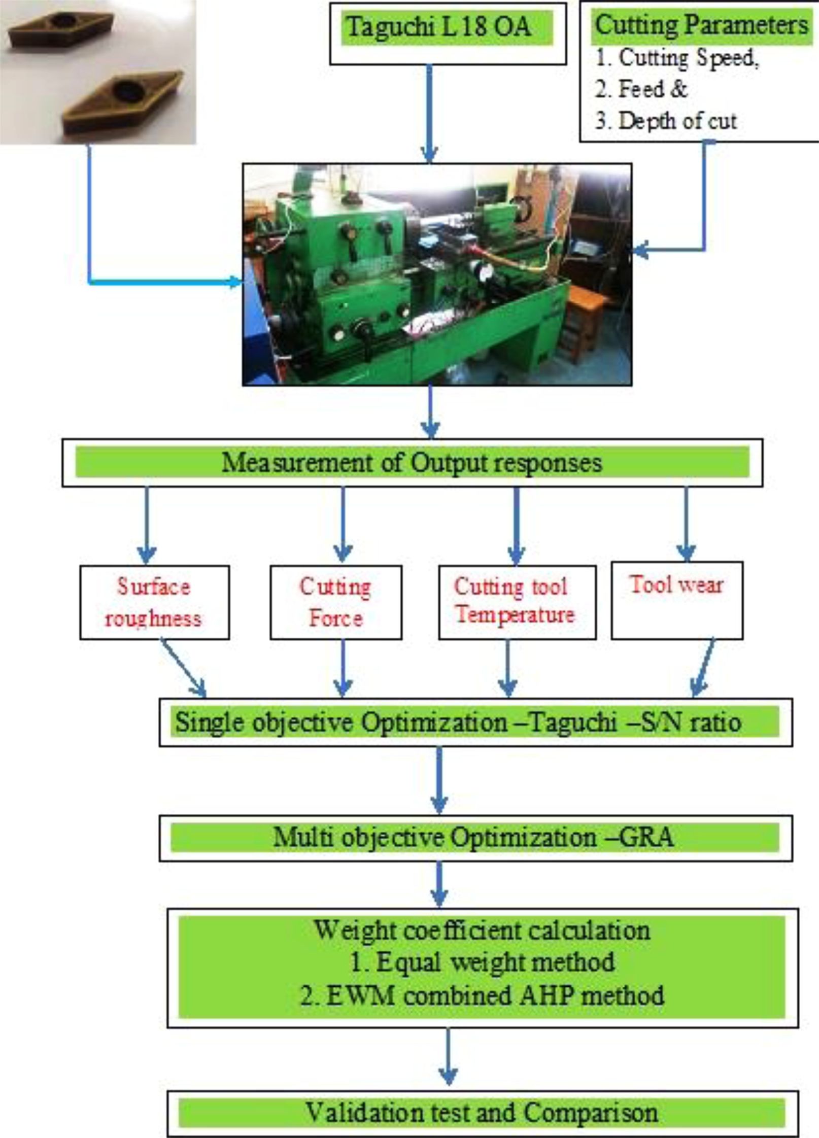
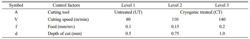
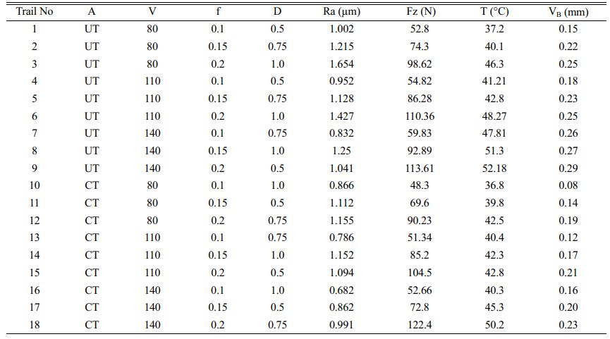
The work material AZ91D Mg alloy has the composition of Al 9.041%, MnO.21%, ZnO.6649%, SiO.0364%, FeO.0025%, CuO.0014%, NiO.0006% and the remaining Mg. The specimen with dimensions of 30 mm diameter and 250 mm length was used for conducting dry turning experiments in centre lathe (Nagmati-175 types) using UT and CT carbide cutting inserts (VBMT160408-LM). Cryogenic treatment includes keeping the inserts in liquid nitrogen for 24 hours and then tempering the tool at 180 °C for 3 hours. The control parameters involved in this test are provided in Table 1. In this study experiments were conducted and responses noted based on Taguchi L18 orthogonal array design as presented in Table 2. In this effort, Ra and Fz were measured by MITUTOYO SJ 210 and Kistler dynamometer (Type 9257B) respectively. Tool temperature and VB were observed with BEETECH MT-4E Infrared Thermometer and Mitutoyo Tool Maker’s Microscope (TM-510 Model) respectively. The approach of this exploration is schematically represented in Fig. 1.
|
Fig. 1 Stages of experimental work and optimization |
Optimization by Taguchi
This exploration is greatly intended on attaining the best possible results with lowest Ra, Fz, T and VB. Therefore “Lower the Better” condition was desired and computing S/N ratio [28-31] was achieved with eq. (1).

Here, n = Total no. of interpretations, y = observed data.
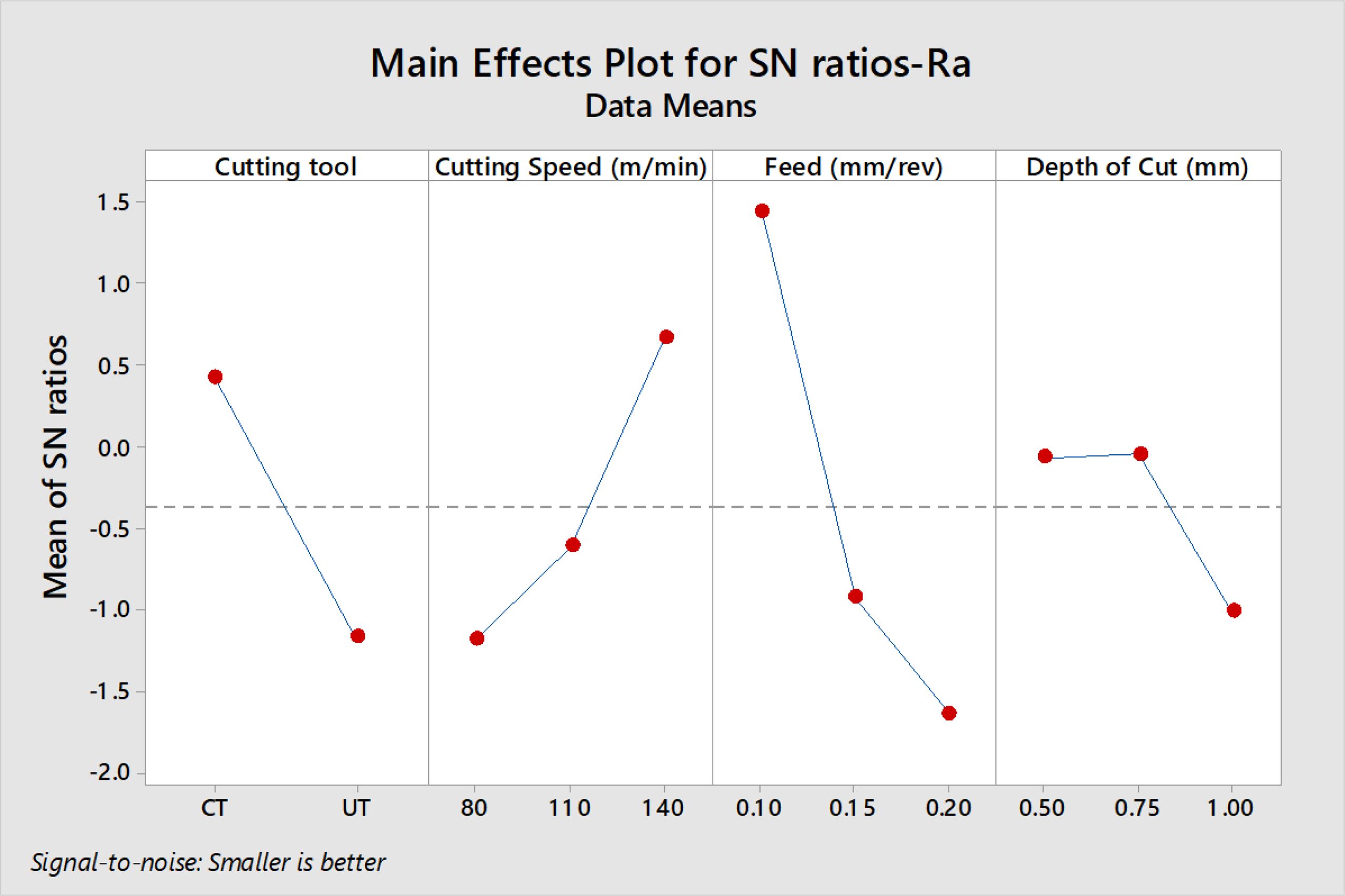
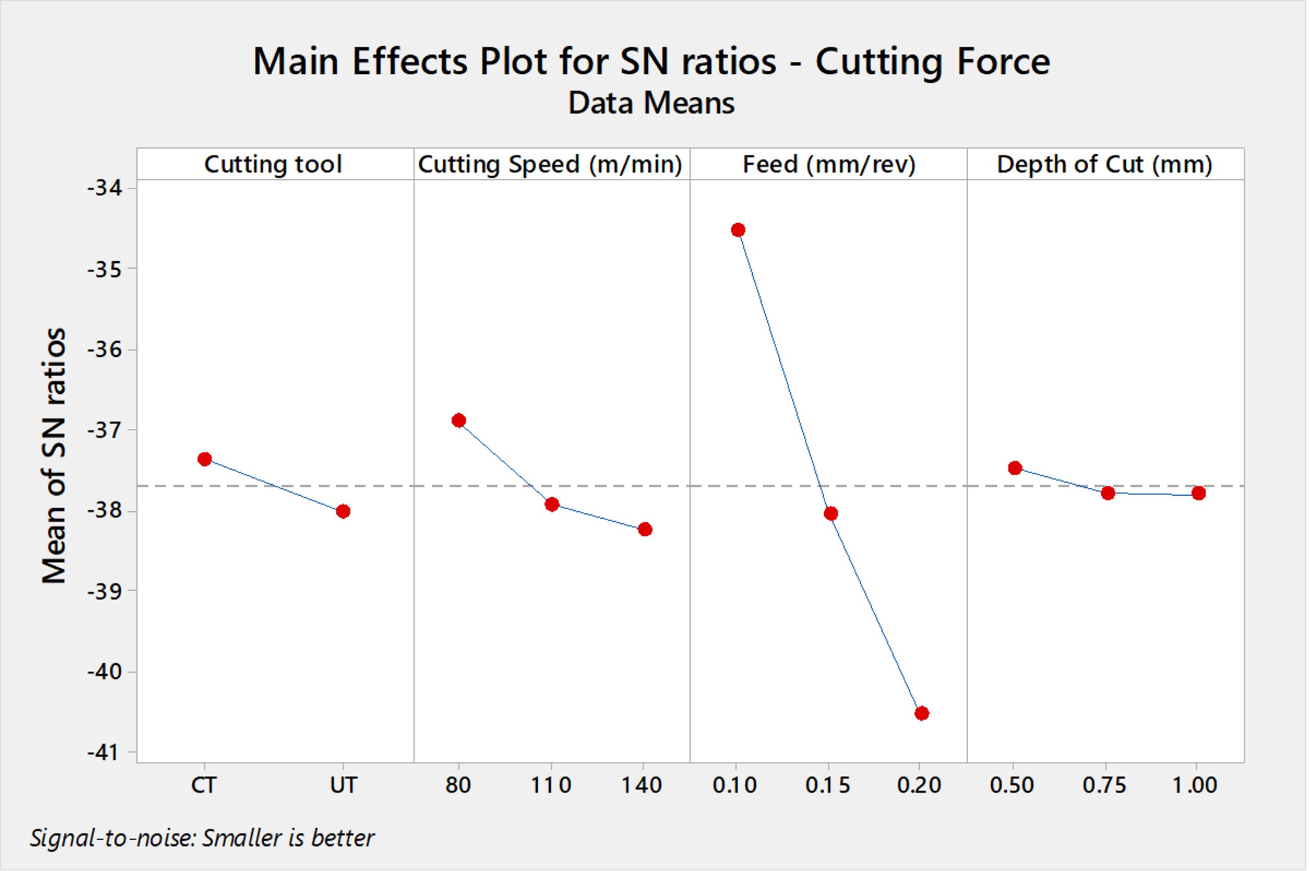
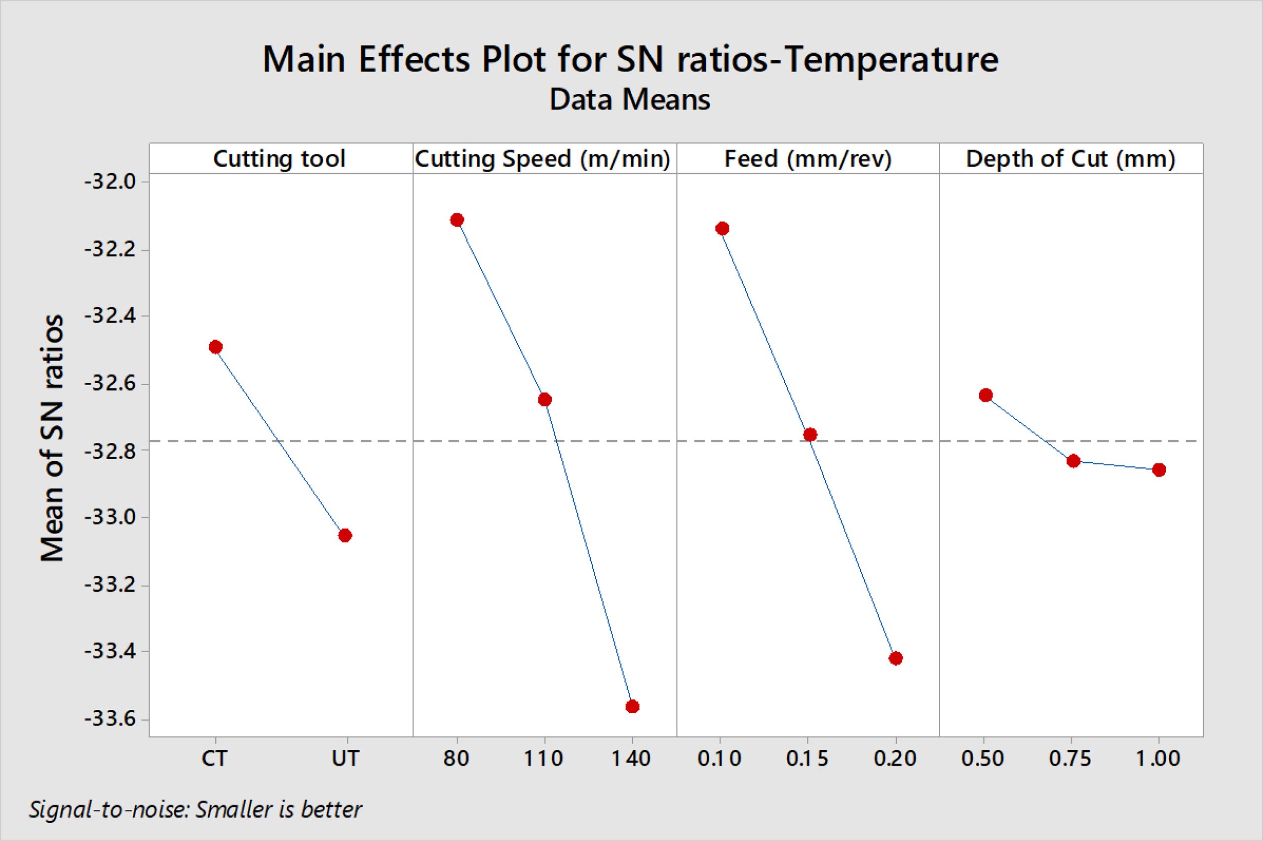
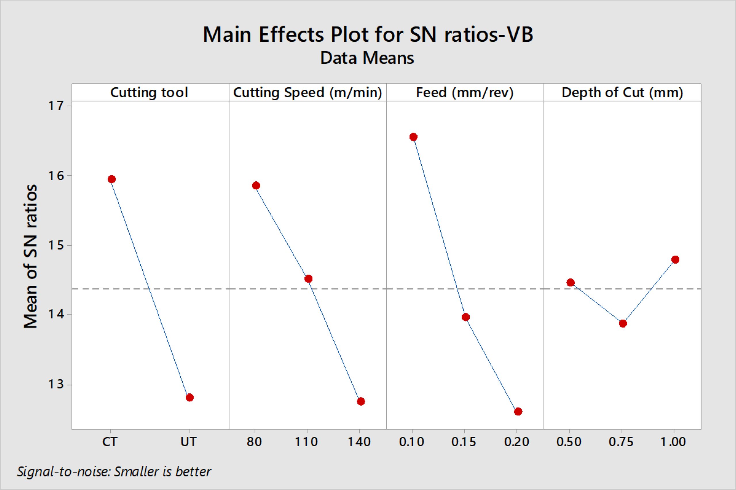
Minitab 19 software was used to obtain the responses of S/N ratios as well as their plots. The mean effects plots for S/N ratios of Ra, Fz, T and VB are indicated in Figs. 2, 3, 4 and 5 respectively.
From Fig. 2 the best combination for minimum Ra is f at 0.1 mm/rev, V at 140 m/min, d at 0.5 mm with CTT.Ra increased as the feed and depth of cut increased, but decreased as the cutting speed increased. According to Table 3 and ANOVA results, it is evident that feed is the dominant factor with an influence of 47.28% on Ra followed by cutting insert. The accuracy of machined surfaces of Mg alloy is mainly determined by feed [8]. Similarly the optimal machining conditions of V at 80 m/min, f at 0.1 mm/rev and d at 0.5 mm with CTT are attained for achieving minimum Fz and T values according to Fig. 3 and 4 respectively. Feed and Cutting speed are the major dominant factors having influences of 88.14% and 45.82% on Fz and T respectively as from ANOVA results. Both Fz and T values increased with increasing cutting speed, feed and depth of cut. The optimum machining conditions for minimum VB is V at 80 m/min, f at 0.1 mm/rev, d at 1.0 mm with CTT as seen from Fig. 5. It also exhibits that increased speed and feed with UT tool result in greater tool wear. Cutting tool shows major influence on VB and contributed with 37.17%. Analysis of all responses revealed that optimal results are obtained only with CT cutting inserts in the machining of Mg alloy.
Optimization by using GRA
Taguchi’s technique is constrained to solve single objective problems only. When many objectives are to be encountered, Taguchi based GRA is preferred. GRAs frequently deal with complicated relations between multiple parameters and responses [32]. In this analysis, GRA is employed to find the optimal setting values relating to diverse responses. The several stages of the GRA method are enumerated in the subsequent segments [33, 34].
Normalization
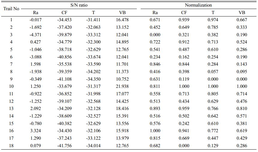
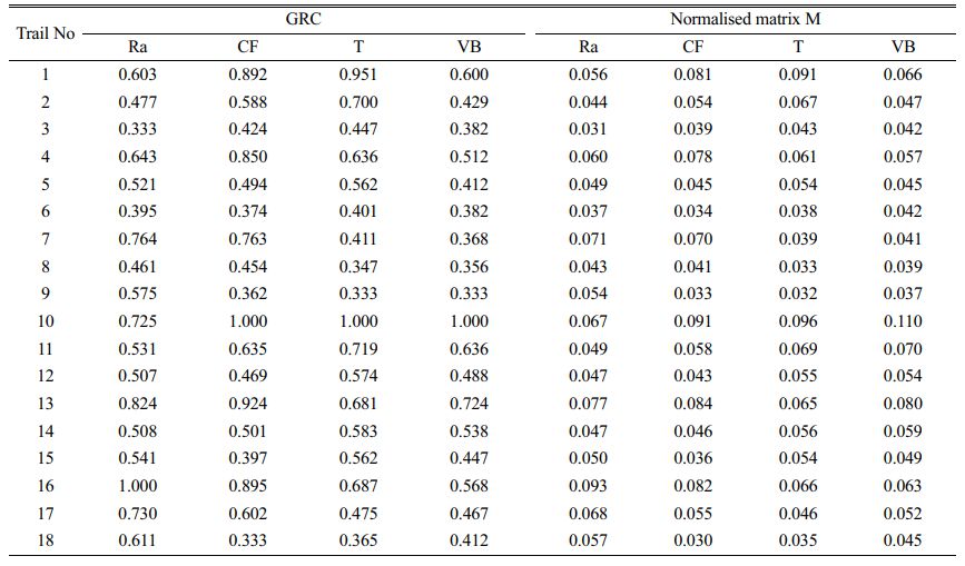
The initial step is data pre-processing in which the original data are normalised and transformed into values between 0 to 1 using Eq. (2) and presented in Table 4. Considering required outputs for Ra, Fz, T and VB in turning, a smaller-the-better performance is chosen to get optimal results.
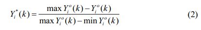
Where Y0i is original data, Yai is normalized data
Grey relational coefficient (GRC)
Subsequent to normalization, the GRC is estimated using the Eq. (3) and presented in Table 5.
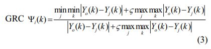
Where, distinguishing coefficient ζ = 0.5 is typically used.
Weight calculation
The weights of the multi-objective responses are required to attain the grey relational grade (GRG). Most of the researchers have used equal weights for all responses, but this technique ignores any variance among the multi-objective characteristics. The weights of diverse responses contrast from one another owing to their dissimilar surface characteristics. Two of these approaches are presented in this paper: the EWM and a hybrid method that uses the EWM in conjunction with the analytic hierarchy process (AHP) to compute weight [35, 36].
a) EqW Method
In this method equal weight is allotted to all response. In this work four response are involved hence equal weight (wj) of 0.25 is assigned to each.
b) EWM combined with AHP (EWM-AHP)
First the weight of the ith trial is to be assessed for each response via Eq. (4) which are listed in Table 7.
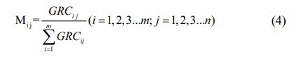
Mij signifies the weight of the ith trial for the jth response and m denotes the total trail.
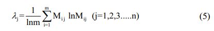
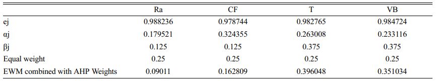
After that, the entropy value for the jth response is calculated. The matrix M can be used to extract the entropy row vector λ.
Then entropy weight vector β is obtained by using Eq. (6):
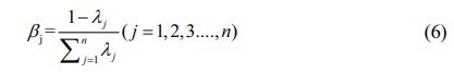
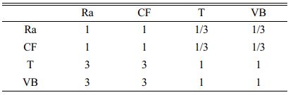
The weight vector β is derived from pairwise comparisons of relative importance of degrees, as described in Table 6.
Subsequently final weight factor is computed using the below expression (7).
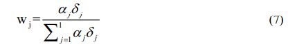
Where, wj is the weight of the jth response. The calculated values of δj, βj and λj and weight of respective response are presented in Table 7.
GRG
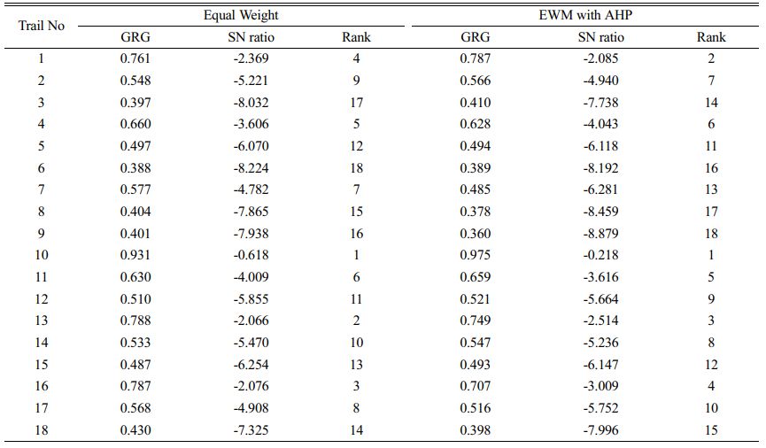
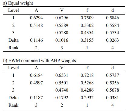
The GRG is computed on the basis of the weight presented in the Table 7 with help of Eq. (8). The resultant GRG and its ranks are shown in Table 8.
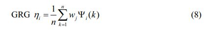
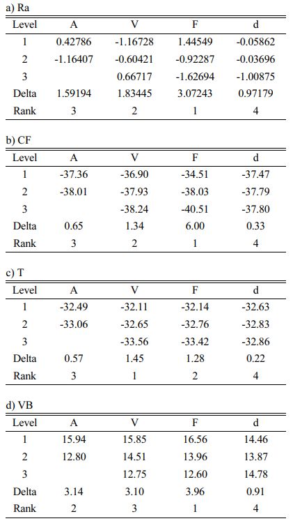
For both EqW and EWM-AHP weights methods, the highest S/N ratio was obtained in the tenth experimental run. As a result, the 10th run was given first place. The mean GRG value was computed which depends upon S/N values and are listed in GRG response Table 9 [37].
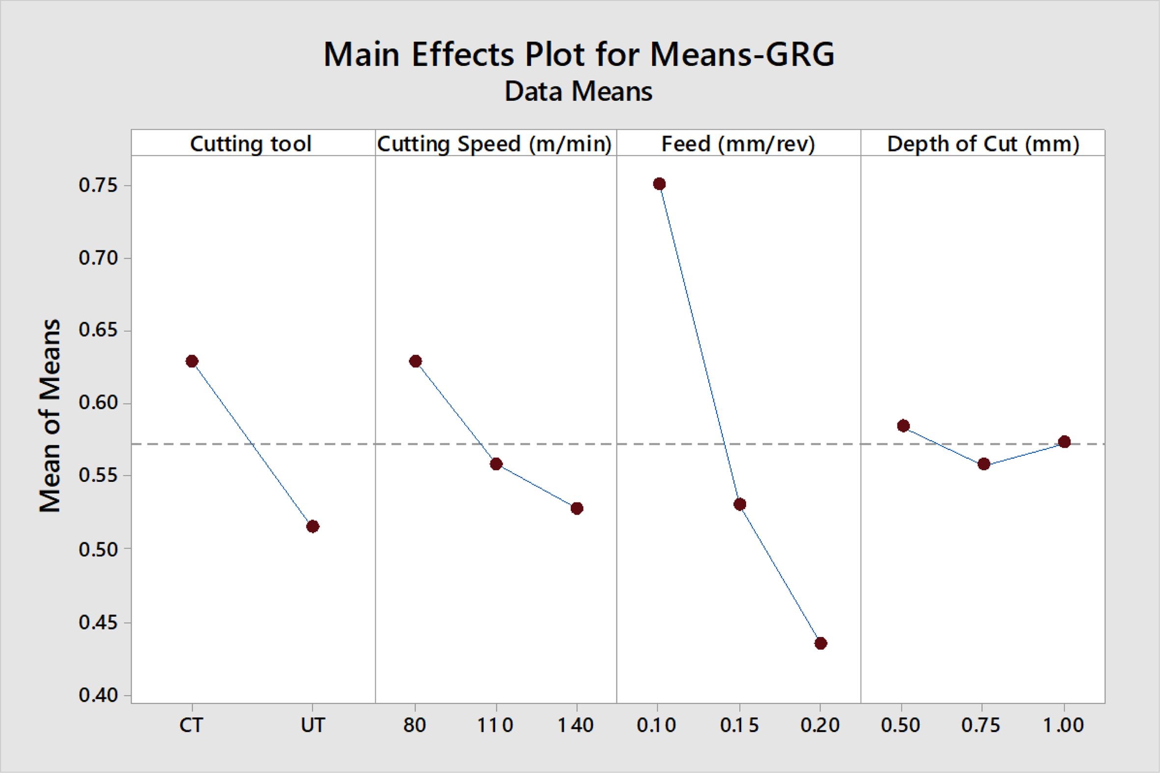
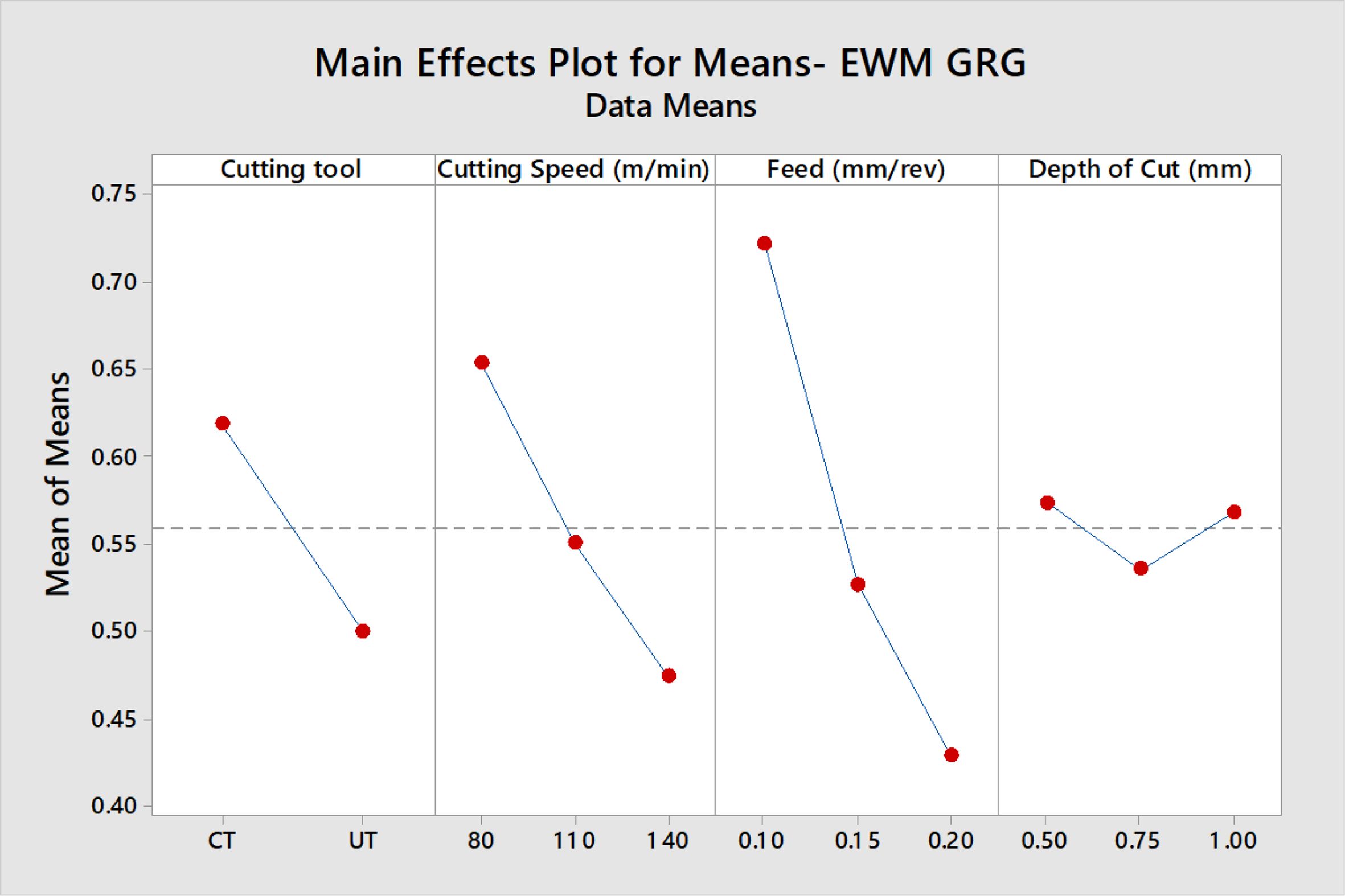
As GRG is a “larger-is-better” quality attribute, maximum GRG values are obtained for f1 at 0.10 mm/rev, V1 at 80 m/min, and d1 at 0.50 mm under CTT, using both weight-assigning methods, as shown in the Mean tables for GRG (Table 9) and Figs. 6 and 7.
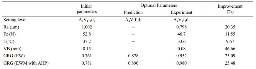
Validation trial (Table 10) is the substantial indication of optimized results [38, 39]. The optimal parameters provides the outcomes are 0.798 µm of Ra, Fz of 46.7N, T at 33.6 °C and 0.08 mm of VB. Ra, Fz, T and VB values are significantly reduced by 20%, 12%, 10% and 46% respectively due to machining with CTT and produced better optimized results. Table 10 also shows that using EqW and EWM-AHP weights, the improvements in GRG are 25.09% and 25.48%, respectively, at optimal conditions. When a multi-objective optimization is performed, GRG with EWM-AHP weights method produces the best results, with a value of 2.94% higher than GRG with EqW.
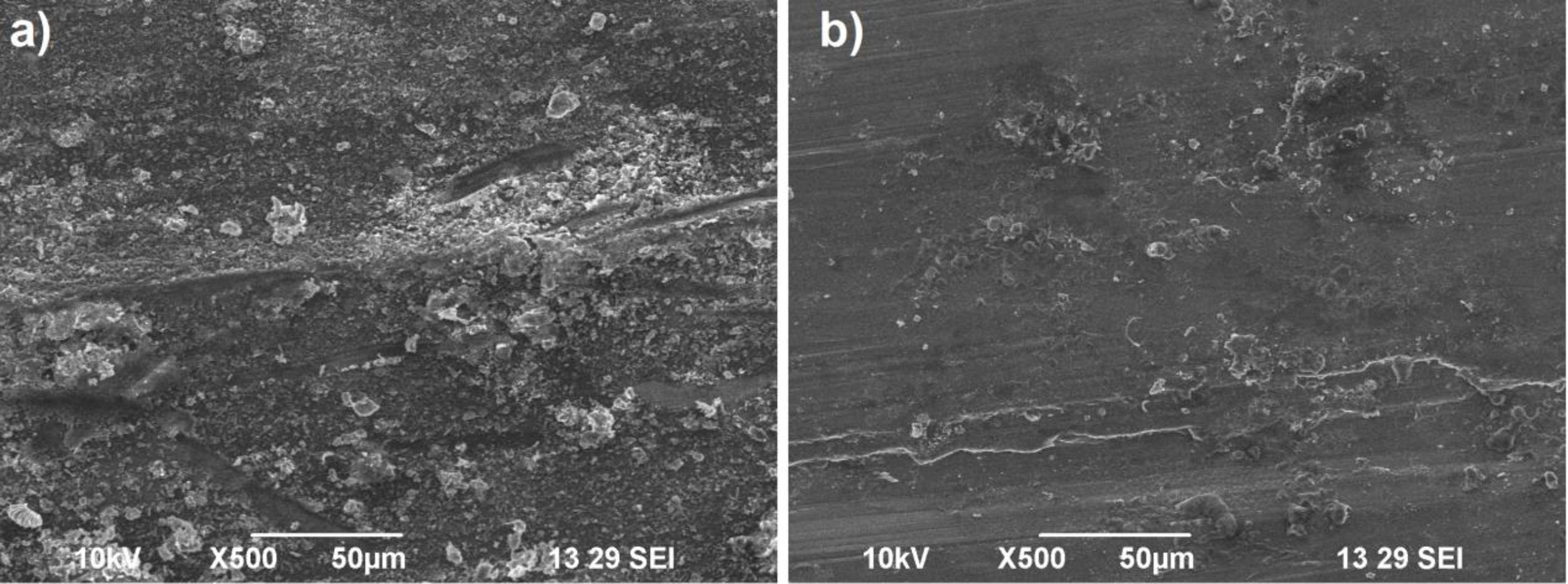
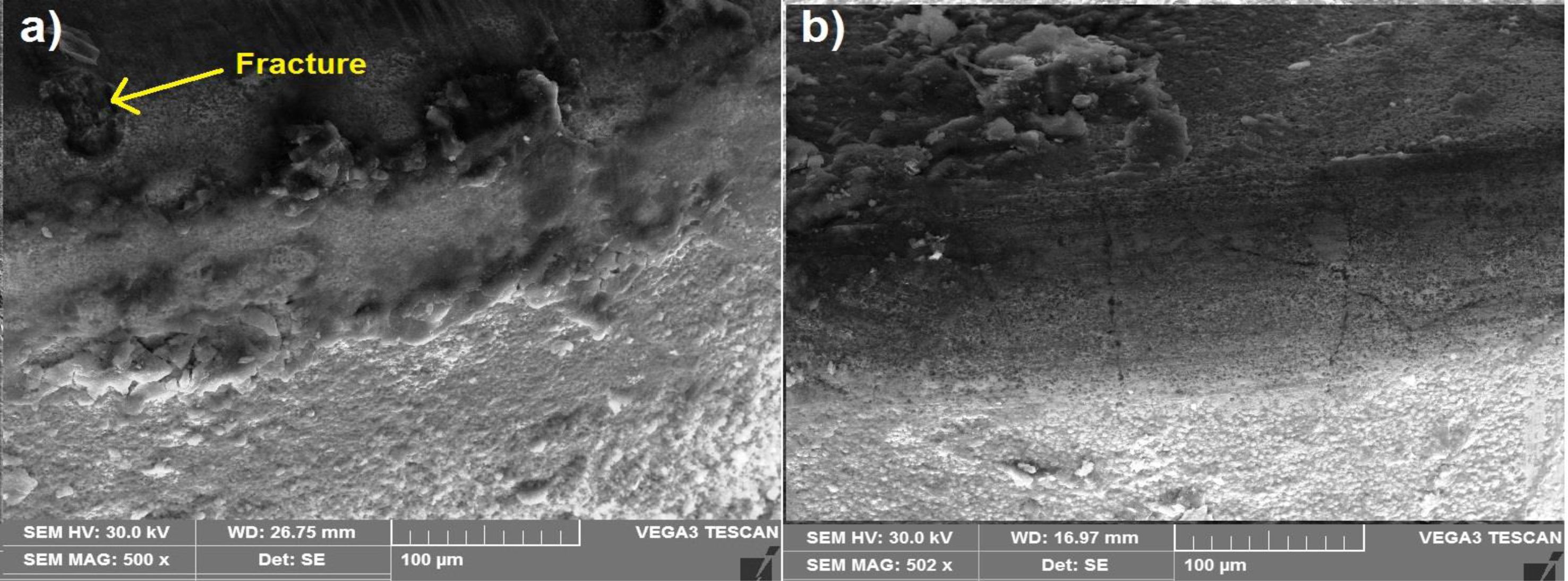
After validation experiment, SEM analysis was conducted to confirm the optimal results. Fig. 8 shows the SEM analysis of surface, in which rough turned surfaces are observed in Fig. 8a. Better surface condition is realized at optimal turning with Ra value of 0.798 µm. From Fig. 9, it is noticed that tool wear is lower in cryogenically treated tool due to increased hardness and wear resistance imparted by the cryogenic treatment. Moreover fracture is noticed on the cutting edge of the UT tool, whereas such fracture could not be found in the CTT.
ANOVA was performed [40, 41] and from its results, for the EqW method, feed provides the foremost influence on GRG (73.08%), followed by cutting tool (13.74%). For the EWM-AHP weights method, the results were different. In the case of EWM, feed is the utmost impact to GRG (57.53%), followed by cutting speed (20.88%). In both methods depth of cut has shown the least contribution to GRG. The R2 values of ANOVA results are 94.87% and 93.14% for both weight methods respectively. These values are close to unity and thus significant.
|
Fig. 2 S/N ratio plot –Ra |
|
Fig. 3 SN ratio plot Fz. |
|
Fig. 4 SN ratio plot -T. |
|
Fig. 5 SN ratio plot –VB |
|
Fig. 6 Main effect plot-EqW GRG |
|
Fig. 7 Main effect plot–EWM GRG |
|
Fig. 8 SEM images of surface at V1f1d1 (80 m/min, 0.1 mm/rev, 0.5 mm) under; a) UT and b) CT |
|
Fig. 9 Tool wear at V1f1d1 (80 m/min, 0.1 mm/rev, 0.5 mm) with; a) UT and b) CT |
This research involves turning experiments conducted on AZ91D Mg alloy with the aim of identifying the influence of cutting factors and the dominant ones among them Ra, Fz, T and VB using GRA technique. Subsequent inferences have been reached from the investigational and optimization works.
For attaining minimum Ra, V at 140 m/min, f at 0.1 mm/rev, d at 0.5 mm for machining with CTT are found to be the optimal condition in the turning of the Mg alloy.
The parametric combination of V at 80 m/min, f at 0.1 mm/rev, d at 0.5 mm for machining with CTT is obtained as the optimal parameters for Fz and cutting tool temperature.
The cutting conditions of V at 80 m/min, f at 0.1 mm/rev, d at 1.0 mm for machining with CTT results in lowest VB value.
As per GRA results, both weight-assigning methods have optimal parameter conditions for minimizing Ra, Fz, T and VB are Cutting tool (CT), 0.1 mm/rev feed, 80 m/min cutting speed and 0.5 mm depth of cut.
Validation test proves that, Ra, Fz, T and VB values are considerably reduced by 20%, 12%, 10% and 46% respectively due to the application of CTT for machining.
Confirmation tests revealed that using EqW and EWM-AHP weights, the enhancements in GRG are 25.09% and 25.48%, respectively, at optimal conditions.
The prediction of GRA for EWM-AHP weights was 2.94% higher compared to EqW method. As a result, this approach can be considered to be the most effective for multi-objective optimization.
- 1. Y.K. Yang and C.J. Tzeng, Mater. Manuf. Process. 21[5] (2006) 489-494.
-

- 2. X. Cao, M. Xiao, M. Jahazi, J. Fournier, and M. Alain, Mater. Manuf. Process. 23[4] (2008) 413-418.
-
- 3. J.E. Gray and B. Luan, J. Alloy. Compd. 336 (2002) 88-113.
-
- 4. H. Friedrich and S. Schumann, J. Mater. Process. Technol. 117[3] (2001) 276-281.
-
- 5. Y. Chunmiao, H. Dezheng, L. Chang, and L. Gang, J. Hazardous Mater. 246 (2013) 283-290.
-
- 6. N. Tomac, K. Tonnessen, and F.O. Rasch, CIRP Annals- Manuf. Technol. 40[1] (1991) 79-82.
-
- 7. E.M. Rubio, María Villeta, Diego Carou, and Adolfo Saa, Int. J. Pre. Eng. Manuf. 15[5] (2014) 929-940.
-
- 8. E.M. Rubio, J.L. Valencia, A.J. Saa, and D. Carou, Int. J. Prec Eng. Manuf. 14[6] (2013) 995-1001.
-
- 9. A. Khan and K. Maity, J. Manuf. Process. 28 (2017) 272-284.
-
- 10. T. Sreerama Reddy, T. Sornakumar, M. Venkatarama Reddy, and R. Venkatram, Int. J. Refract. Met. Hard Mater. 27[1] (2009) 181-185.
-
- 11. K.H.W. Seah, M. Rahman, and K.H. Yong, Proc. Inst. Mech. Engineers, Part B: J Eng. Manuf. 217[1] (2003) 29-43.
-
- 12. D. Mohan Lal, S. Renganarayanan, and A. Kalanidhi, Cryogenics 3 (2001) 149-155.
-
- 13. Celik Osman Nuri, Sert Abdullah, Gasan Hakan, and Ulutan Mustafa, Int. J. Adv. Manuf. Technol. 95 (2018) 2989-2999.
-
- 14. A.Y.L. Yong, K.H.W. Seah, and M. Rahman, Int. J. Mac. Tools & Manuf. 46 (2006) 2051-2056.
-
- 15. S. Ramesh, R. Viswanathan, and S. Ambika, Measurement 78 (2016) 63-72.
-
- 16. R. Viswanathan, S. Ramesh, and V. Subburam, Measurement 120 (2018) 107-113.
-
- 17. R. Viswanathan, S. Ramesh, S. Maniraj, and V. Subburam, Measurement 159 (2020) 107800.
-
- 18. S. Dinesh, V. Senthilkumar, P. Asokan, and D. Arulkirubakaran, Mater. Des. 87 (2015) 1030-1036.
-
- 19. R.G. Deshpande and K.A. Venugopal, Mater. Today: Proc. 5 (2018) 1872-1878.
-
- 20. U. Koklu and H. Coabn, J. Mat. Res. Tech. 9[3] (2020) 2870-2880.
-
- 21. Xuhong Guo, Lijun Teng, Wei Wang, and Tingting Chen, Adv. Mater. Res. 102-104 (2012) 653-657.
-
- 22. K. Gunasekaran, G. Pradeep Kumar, and R. Thanigaivelan, J. of New Mater. Electro. Sys. 24[1] (2021) 49-54.
-
- 23. V. Sivalingam, Jie Sun, Bin Yang, Kai Liu, and Ramesh Raju, J. Manuf. Proc. 36 (2018) 188-196.
-
- 24. K. Vadivel and R. Rudramoorthy, Int. J. Adv. Manuf. Technol. 42 (2009) 222-232.
-
- 25. B.N. Sahoo, A. Mohanty, S. Gangopadhyay, and K. Vipindas, J. Manuf. Proc. 58 (2020) 819-831.
-
- 26. N.A. Ozbek, J. Mat. Res. Tech. 9[4] (2020) 9442-9456.
-
- 27. A. Cicek, I. Uygur, T. Kıvak, and N. Altan Ozbek, J. Manuf. Sci. Eng. 134 (2012) 1-6.
-
- 28. M. Srinivasan, S. Ramesh, S. Sundaram, and R. Viswanathan, J. Ceram. Process. Res. 22[3] (2021) 345-355.
-
- 29. N. Sivashankar, R. Viswanathan, K. Periasamy, R. Venkatesh, and S. Chandrakumar, Mater. Today: Proc. 37[2] (2021) 214-219.
-
- 30. S. Maniraj and R. Thanigaivelan, Trans. Ind. Inst. Met. 72[12] (2019) 3057-3066.
-
- 31. K.G. Saravanan, A. Sivapragasam, R. Prabu, and S. Maniraj, Mater. Today: Proc. 45 (2021) 1975-1978.
-
- 32. J.U. Pillai, I. Sanghrajka, M. Shunmugavel, T. Muthuramalingam, M. Goldberg, and G. Littlefair, Measurement. 124 (2018) 291-298.
-
- 33. M. Mia, A. Rifat, M.F. Tanvir, M.K. Gupta, M.J. Hossain, and A. Goswami, Measurement 129 (2018) 156-166.
-
- 34. M. Mia, M. Al Bashir, M.A. Khan, and N.R. Dhar, Int. J. Adv. Manuf. Technol. 89[1-4] (2017) 675-690.
-
- 35. E. Suneesh and M. Sivapragash, Measurement 168 (2021) 108345.
-
- 36. S. Maniraj, R. Thanigaivelan, R. Kannan, N. Ramesh, and P. Raja, Mater. Today: Proc. 45 (2021) 2430-2434.
-
- 37. A. Kanakaraj, R. Mohan, and R. Viswanathan J. Ceram. Process. Res. 23[3] (2022) 268-277.
-
- 38. K. Periasamy, N. Sivashankar, R. Viswanathan, and J Balaji, J. Ceram. Process. Res. 23[3] (2022) 335-343.
-
- 39. T. Tamilanban, T.S. Ravikumar, C. Gopinath, and S. Senthilrajan, J. Ceram. Process. Res. 22[6] (2021) 629-635.
-
- 40. M. Shivaperumal, R. Thirumalai, S. Kannan, and K.S.S. Rao Yarrapragada, J. Ceram. Process. Res. 23[3] (2022) 404-408.
-
- 41. R. Viswanathan, S. Ramesh, N. Elango, and D. Kamesh Kumar, Pert. J. Sci. Tech. 25[1] (2017) 255-262.
 This Article
-
2023; 24(1): 142-152
Published on Feb 28, 2023
- 10.36410/jcpr.https://doi.org/10.36410/jcpr.2023.24.1.142
- Received on Jul 8, 2022
- Revised on Aug 19, 2022
- Accepted on Sep 26, 2022
Services
Shared
Correspondence to
- N. Ravikumar
-
Department of Mechanical Engineering, Kongunadu College of Engineering and Technology, Trichy, India
Tel : +91 9894160222 - E-mail: suryakumar08@gmail.com
Clean-Energy Research Institute(CRI), Hanyang University, 222, Wangsimni-ro, Seongdong-gu, Seoul, 04763, Korea
E-mail: jcpr@hanyang.ac.kr