


- Structural and magnetic properties of M-type Sr0.1Ca0.4La0.5Fe12O19 ferrites: The effects of CoxFe3-xO4 in precursor
Xiubin Zhaoa, Shuang Zhanga, Jinsong Lia, Ailin Xiaa,* and Yujie Yangb
aSchool of Materials Science and Engineering, Anhui University of Technology, Maanshan 243002, China
bSchool of Materials Science and Engineering, Anhui University, Hefei 230601, ChinaThis article is an open access article distributed under the terms of the Creative Commons Attribution Non-Commercial License (http://creativecommons.org/licenses/by-nc/4.0) which permits unrestricted non-commercial use, distribution, and reproduction in any medium, provided the original work is properly cited.
M-type ferrite Sr0.1Ca0.4La0.5Fe12O19 magnetic powders doped with CoxFe3-xO4 (0 ≤ x ≤ 1.25) in precursors were prepared by a ceramics process. The structure of specimens were examined by using an X-ray diffractometer. Only the magnetoplumbite phase was found in the specimens with the cobalt content (x) from 0.25 to 1.25 in precursor. The specimens exhibited a typical hexagonal M-type structure and the particles in specimens were uniformly distributed in size. The specimen with x=1.25 had the maximum saturation magnetization of 67.48 emu/g, while the residual magnetization and the coercivity of the specimen with x=1.00 reached the maximum value of 31.83 emu/g and 1270 Oe, respectively
Keywords: M-type ferrite, Cobalt content, Ceramic method, Magnetic properties
M-type permanent magnetic ferrite (SrFe12O19, SrM) is widely used due to its relatively high saturation magnetization (Ms) and coercivity (Hc). Besides, it has fine magnetocrystal anisotropy constant, excellent corrosion resistance and chemical stability [1-4]. Currently, some metal ions, such as Co2+, La3+, Ca2+, Cu2+, La3+-Co2+, La3+-Zn2+ and so on, are substituted or doped into the SrM ferrites attempting to improve the magnetic properties for the sake of special application [5-20]. Kools et al. [16] studied the structural and magnetic properties of M-type ferrite doped by La-Co ions. It was found that Co2+ ions replaced Fe3+ ions on octahedral lattice points 4f2 and 2a, and the magnetic properties were improved through the 4f2 substitution. A.L. Xia et al. [17] prepared the SrFe12O19-CoFe2O4 nanocomposites by using a hydrothermal method. The study found that compared with single-phase SrFe12O19, when the exchange coupling appeared, with the increasing content of CoFe2O4, the Ms of composites increased significantly from 59.2 emu/g to 72.4 emu/g. W.C. Li et al. [18] prepared La-Co substituted Sr1-xLaxFe12-xCoxO19 ferrite via a sol-gel combustion method. It was found that the Ms reached the maximum value when the La-Co substitution was x=0.3. S.M. Masoudpanah et al. [19] prepared the La-Co substituted M-type ferrite thin films by using laser deposition. The results showed that the Ms increased first and then decreased with the increasing La-Co amount. Y. Liu et al. [20] prepared the La-Co substituted M-ferrite by co-improved precipitation and molten salt method, and the results showed that the Ms and Hc were comparable to those synthesized via a high-temperature method. However, the influence of different cobalt content in precursor on the magnetic properties of SrM ferrites is still not reported. Through this study, it may help enterprises reduce the use of rare earth elements in production
In this study, the SrM magnetic powders were obtained via a ceramic process with different CoxFe3-xO4 (0 ≤ x ≤ 1.25) precursors. The effects of the cobalt content (x) in precursor on the structural and magnetic properties of specimens were studied.
Preparation of CoxFe3-xO4 (0 ≤ x ≤ 1.25) precursors
All specimens with a nominal composition of CoxFe3-xO4 (0 ≤ x ≤ 1.25 with steps of 0.25) were obtained via a traditional ceramic process. All the chemical reagents used were analytically pure (Fe2O3 and Co2O3). The mixed powders (Fe2O3 and Co2O3) were ball-milled in water for 2 h, and then the powders obtained were dried, sifted and sintered at 850 ℃ for 3 h in air. Finally, the sintered samples were pulverized to powders with a size of smaller than 100 μm.
Preparation of M-type ferrite Sr0.1Ca0.4La0.5Fe12O19 powders with different cobalt content in precursor
All the Sr0.1Ca0.4La0.5Fe12O19 powder specimens with different CoxFe3-xO4 (0 ≤ x ≤ 1.25) precursors were obtained by using a ceramic process. The analytically pure Fe2O3 (98% purity), SrCO3 (98% purity), CaCO3 (99% purity) and La2O3 (99% purity) were used as raw materials to prepare SrM ferrites. The mixed powders were milled for 2 h, together with CoxFe3-xO4 of 3 wt%. The obtained powders were dried, sifted, and then sintered at 1300 ℃ for 2 h in the air atmosphere in a muffle furnace. Finally, the sintered specimens were pulverized to powders with a size of smaller than 100 μm.
Characterization
The phase identification of specimens was obtained on a PANalytical X’Pert Pro diffractometer (Almelo, Netherlands) using Cu Kα (λ = 1.5406 Å) radiation. The morphologies were examined by a HITACHI S-4800 field emission scanning electron microscopy (FESEM, Tokyo, Japan). The room temperature (RT) magnetic hysteresis loops of specimens were measured on a MicroSense EZ7 vibrating sample magnetometer (VSM) with a maximum external field of 20,000 Oe.
Structural and morphological properties
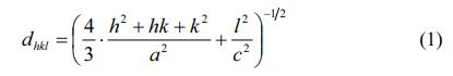
Fig. 1 shows the XRD patterns of SrM specimens obtained with different cobalt content (x) from 0 to 1.25 in precursors. As shown, in the specimens with x from 0.25 to 1.25, only typical peaks from single-phase magnetoplumbite SrM was found, which implies that the Co2+ ions entered into the magnetoplumbite lattice without producing any second phase.
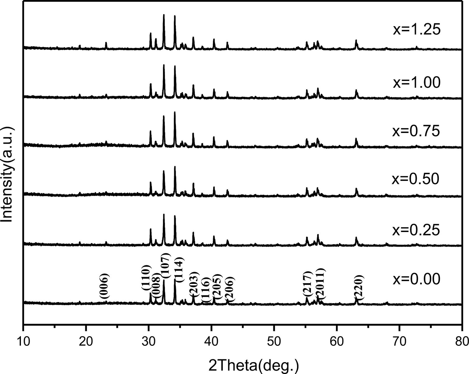
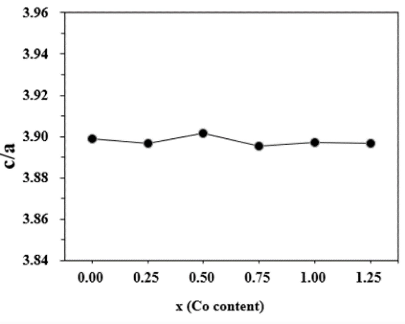
The lattice constants a and c can be calculated using the values of Miller indices (h, k, l) and the inter-planer spacing dhkl corresponding to (107) and (114) peaks according to the following formula (1):
The variations of lattice constants a and c of the specimens with different cobalt content (x) are shown in Fig. 2. It can be found that the c decreases slightly from 22.9725 Å (x=0.00) to 22.9616 Å (x=0.25). When the x ranges from 0.25 to 0.50, the c increases to 22.9847 Å. With a further increase of x from 0.50 to 1.00, the c decreases to 22.9624 Å. From 1.00 to 1.25, the c increases to 22.9689 Å. However, compared with c, the variation of a is not obvious, suggesting that the x affected c more greatly. This may result from the different distribution of Co ions.
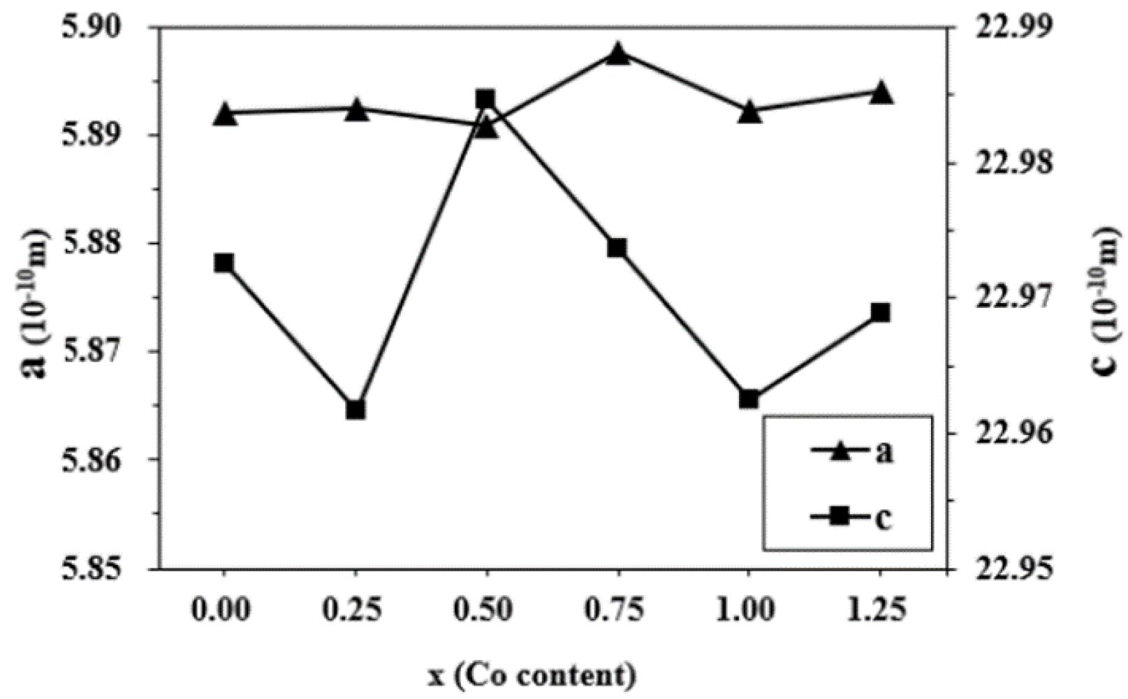
Fig. 3 indicates the change of crystal axis ratio of c/a in different specimens. The c/a is approximately the same in Fig. 3. On the basis of Verstegen and Stevels [26], the value of c/a ratio may present the structure type. For the M-type structure, the ratio was assumed to be smaller than 3.98. Herein, the values of c/a ratio for the specimens range from 3.8954 to 3.9018, which seems to be in well accord with the reported range of M-type structure.
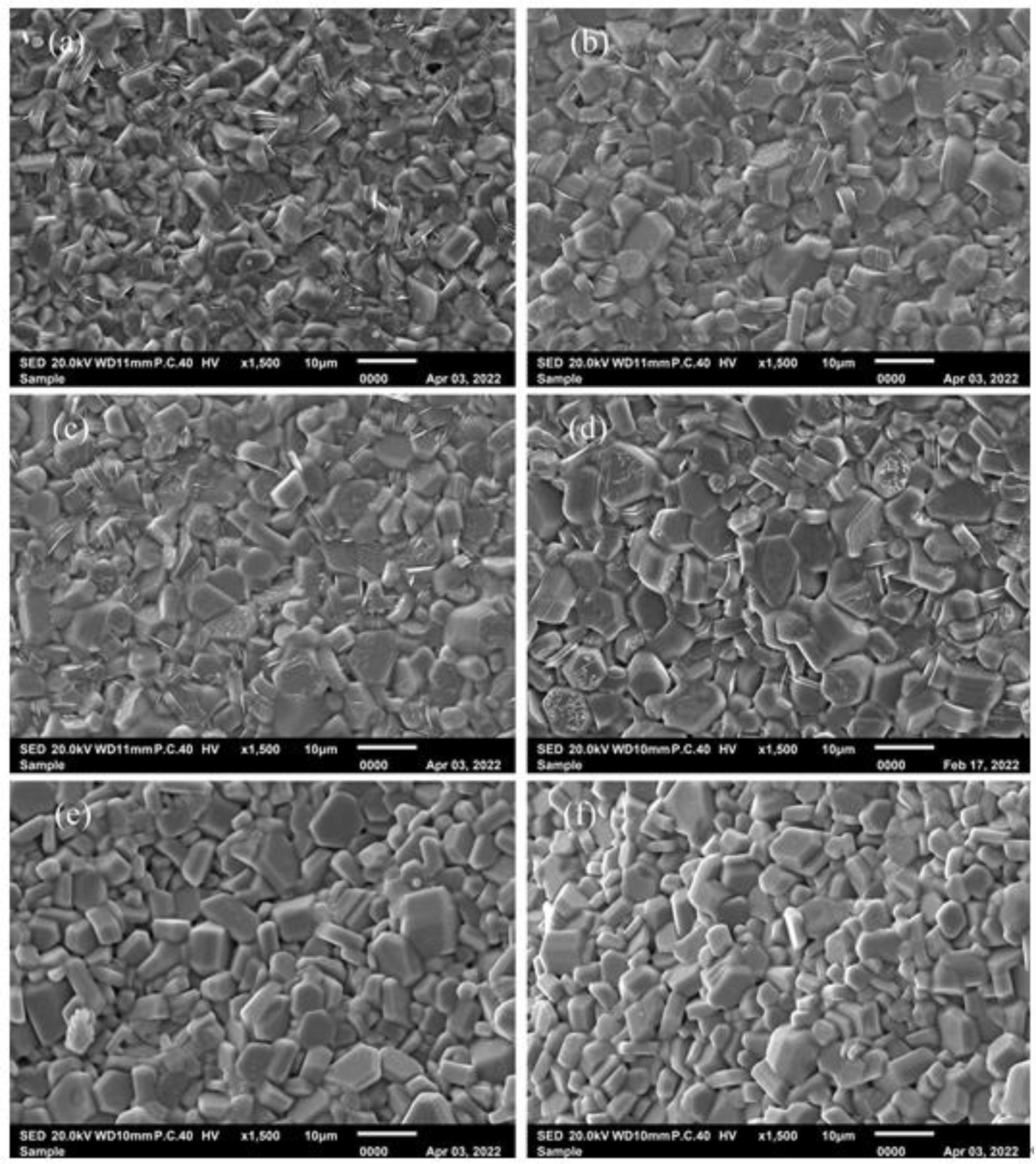
Figure 4shows the typical FESEM images of specimens. As shown in Fig. 4, all the specimens consist of the relatively uniform particles with typical hexagonal structure. It can be found that the average particle size of specimen with x = 0 is obviously smaller than those of specimens with x > 0. However, with the increasing x, the typical morphology and the average particle size of specimens did not change obviously.
Magnetic properties
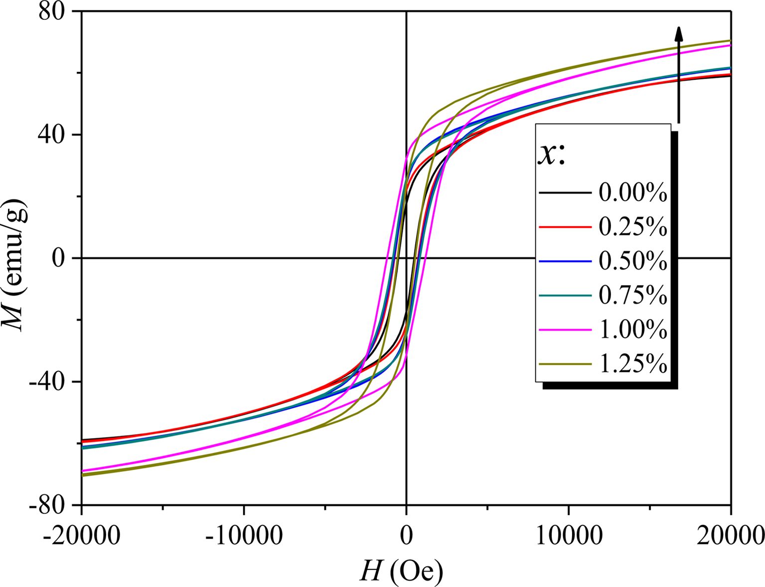
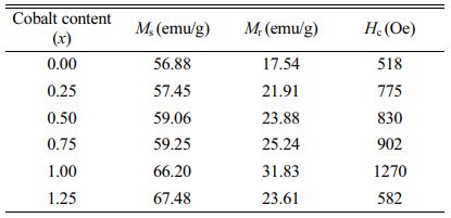
Fig. 5 shows the RT magnetic hysteresis loops of specimens with different x. The Ms, Hc and residual magnetization (Mr) of specimens with different x were determined from Fig. 5 and are listed in Table 1. What should be pointed out is that since the magnetic hysteresis loops were roughly saturated at a field of 20 kOe, the value of magnetization obtained at 20 kOe can approximately be used as Ms.
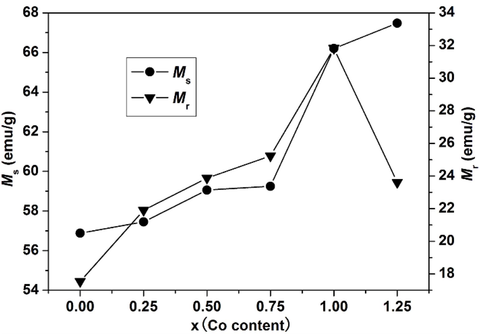
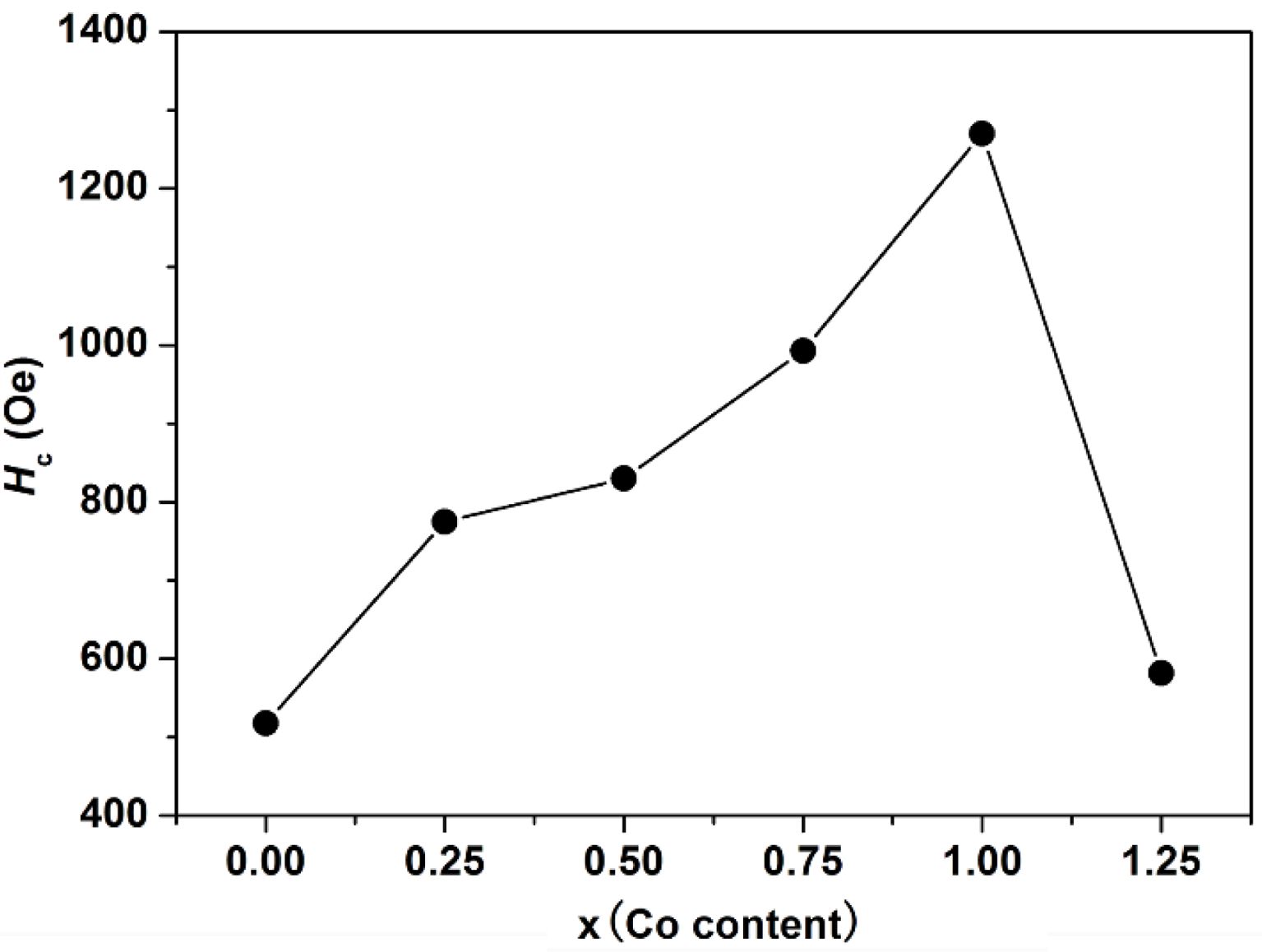
As can be seen from Table 1 and Fig. 6, the Ms of specimens increases with the increase of x from 0 to 1.25, and it reaches 67.48 emu/g when x=1.25. The Mr of specimens increases with the increase of x from 0 to 1.00. When x increased from 1.00 to 1.25, the Mr decreases, and the maximum value is 31.83 emu/g (x=1.00). It is evident that the Hc has the same feature as Ms as shown in Table 1 and Fig. 7. The specimen with x=1.00 exhibits the best magnetic properties, including the Ms (66.2 emu/g), the Mr (31.83 emu/g) and the Hc (1270 Oe). The variation of Ms and Hc with different x is in agreement with those reported in Ref. [17] and Refs. [20-21], respectively. However, the Ms, the Mr and the Hc of specimens are lower than those reported by Rashad et al. [27]. The Mössbauer investigations of La–Co-substituted M-type ferrites revealed that La3+ ions can replace the most Sr2+ ions, and a valence change of some Fe3+ to Fe2+ ions occurred in the 2a and 4f2 sites, while Co2+ ions mainly replaced Fe3+ at 4f2 octahedral sites [22-24]. When x is smaller (larger) than 1.0, the magnetic moment difference caused by Co substitution is positive (negative), respectively, resulting in the Mr of specimen increases first and then decreases with the increase of x.
G. Asti et al. [25] found that the magnetocrystal anisotropy field of ferrite increased with the increase of cobalt content, and the Mössbauer spectrum analysis of ferrite revealed that when the content of cobalt substitution is within a certain range, most of the Co2+ ions will substitute Fe3+ ions in 4f2 and 2a octahedral sites. The magnetocrystal anisotropy constant K1 increases with the increase of cobalt content (x), and consequently the Hc was enhanced. With the increasing ratio of x, Co2+ replaces Fe3+ ions at 2b octahedral sites, thus reducing K1 and Hc.
|
Fig. 1 XRD patterns of specimens obtained with different x. |
|
Fig. 2 The lattice constants a and c of specimens with different cobalt content (x). |
|
Fig. 3 The crystal axis ratio of c/a in the specimens with different x. |
|
Fig. 4 Typical SEM images of specimens with different x. x: (a) 0, (b) 0.25, (c) 0.50, (d) 0.75, (e) 1.00 and (f) 1.25. |
|
Fig. 5 RT magnetic hysteresis loops of specimens with different cobalt content (x). |
|
Fig. 6 The Ms and Mr of specimens with different cobalt content (x). |
|
Fig. 7 The Hc of specimens with different x. |
The M-type Sr0.1Ca0.4La0.5Fe12O19 ferrite powders were obtained via a ceramic process with different CoxFe3-xO4 (0 ≤ x ≤ 1.25) precursors. The XRD patterns showed that the single magnetoplumbite phase was obtained in all the specimens. The SEM study manifested that the particles were distributed uniformly in the specimens. The VSM study indicated the Ms of specimens increased with the increasing x from 0 to 1.25, and reached the maximum value at x=1.25, while the Mr of specimens increased with the increasing x from 0 to 1.25. The specimen with x=1.00 exhibited the best magnetic properties of Ms=66.2 emu/g, Mr =31.83 emu/g and Hc=1270 Oe. The cost of SrM may be reduced through tailoring the content of Co to reduce the usage of rare earth elements.
- 1. Y.J. Yang, F.H. Wang, and D.H. Huang, J. Magn. Magn. Mater. 452 (2018) 100-107.
-

- 2. A.L. Xia, T. Zhan, and R. Sun, J. Alloy. Compd. 784 (2019) 276-281.
-
- 3. M. Manikandan and C. Venkateswaran, J. Magn. Magn. Mater. 358-359 (2014) 82-86.
-
- 4. R.C. Pullar, Prog. Mater. Sci. 57 (2012) 1191-1334.
-
- 5. Y.J. Yang, X.S. Liu, and S.J. Feng, Chinese. J. Phys. 63 (2020) 337-347.
-
- 6. W.C. Li, X.J. Qiao, and M.Y. Li, Mater. Res. Bull. 48 (2013) 4449-4453.
-
- 7. T.P. Xie, L.J. Xu, and C.L. Liu, Powder. Technol. 232 (2012) 87-92.
-
- 8. C.A. Herme, P.G. Bercoff, and S.E. Jacobo, Mater. Res. Bull. 47 (2012) 3881-3887.
-
- 9. Y.Q. Li, Y. Huang, S.H. Qi, F.F. Niu, and L. Niu, J. Magn. Magn. Mater. 323 (2011) 2224-2232.
-
- 10. A. Thakur, R.R. Singh, and P.B. Barman, J. Magn. Magn. Mater. 326 (2013) 35-40.
-
- 11. Y.J. Yang, J.X. Shao, and F.H. Wang, J. Ceram. Process. Res. 18 (2017) 242-246.
-
- 12. Y.J. Yang and J.X. Shao, J. Ceram. Process. Res. 18 (2017) 394-398.
-
- 13. M.J. Iqbal, M.N. Ashiq, and I.H. Gul, J. Magn. Magn. Mater. 322 (2010) 1720-1726.
-
- 14. A. Cavalieri, T. Caronna, and I. Natali Sora, Ceram. Int. 38 (2012) 2865-2872.
-
- 15. M.J. Iqbal and M.N. Ashiq, Chem. Eng. J. 136 (2008) 383-389.
-
- 16. F. Kools, A. Morel, and R. Grössinger, J. Magn. Magn. Mater. 242-245 (2002) 1270-1276.
-
- 17. A.L. Xia, S.Z. Ren, and J.S. Lin, J. Alloy. Compd. 653 (2015) 108-116.
-
- 18. W.C. Li, X.J. Qiao, and M.Y. Li, Mater. Res. Bull. 48 (2013) 4449-4453.
-
- 19. S.M. Masoudpanah, S.A.S. Ebrahimi, and C.K. Ong, J. Magn. Magn. Mater. 342 (2013) 134-138.
-
- 20. Y. Liu. M.G.B. Drew, and Y. Liu, J. Magn. Magn. Mater. 322 (2010) 3342-3345.
-
- 21. T. Kikuchi and T. Nakamura, J. Magn. Magn. Mater. 322 (2010) 2381-2385.
-
- 22. P. Tenaud, A. Morel, and F. Kools, J. Alloy. Compd. 370 (2004) 331-334.
-
- 23. L. Lechevallier, J.M. Le Breton, and J.F. Wang, J. Phys-Condens Mat. 16 (2004) 5359-5376.
-
- 24. L. Lechevallier and J.M. Le Breton, Physica B. 327 (2003) 135-139.
-
- 25. G. Asti, F. Bolzoni, and J.M. Le Breton, J. Magn. Magn. Mater. 272-276 (2004) e1845-e1846.
-
- 26. G.B. Teh, Y.C. Wong, and R.D. Tilley, J. Magn. Magn. Mater. 323 (2011) 2318-2322.
-
- 27. M.M. Rashad and I.A. Ibrahim, J. Mater. Sci-Mater. El. 22 (2011) 1796-1803.
-
 This Article
-
2023; 24(1): 98-102
Published on Feb 28, 2023
- 10.36410/jcpr.2023.24.1.98
- Received on Jun 29, 2022
- Revised on Aug 13, 2022
- Accepted on Sep 3, 2022
Services
Shared
Correspondence to
- Ailin Xia
-
School of Materials Science and Engineering, Anhui University of Technology, Maanshan 243002, China
Tel : +86 13665557919 Fax: +86 05552311570 - E-mail: alxia@126.com
Clean-Energy Research Institute(CRI), Hanyang University, 222, Wangsimni-ro, Seongdong-gu, Seoul, 04763, Korea
E-mail: jcpr@hanyang.ac.kr