


- Flexural behaviour of HPC beams with steel slag aggregate
M. Verapathrana,*, S. Vivekb, G.E. Arunkumarc and Duraisamy Dhavashankarand
aDepartment of Civil Engineering, Dr, N.G.P. Institute of Technology, Coimbatore-641048, India
bDepartment of Civil Engineering, Hindusthan College of Engineering & Technology, Coimbatore-641032, India
cDepartment of Civil Engineering, Shree Venkateshwara Hi-Tech Engineering College, Gobichettipalayam-638455, India
dDepartment of Civil Engineering, Kongunadu College of Engineering & Technology, Thottiam-621215, IndiaThis article is an open access article distributed under the terms of the Creative Commons Attribution Non-Commercial License (http://creativecommons.org/licenses/by-nc/4.0) which permits unrestricted non-commercial use, distribution, and reproduction in any medium, provided the original work is properly cited.
Experimental and analytical woks carried out to investigate the flexural behaviour of High Performance Concrete (HPC) beams are explained in this paper. Reinforced concrete (RC) beams are cast with conventional concrete (CC), HPC with conventional aggregates (HPCF and HPCS) and HPC with steel slag aggregate (HPC7F and HPC7S). The load deflection characteristics, mode of failure, ductility and stiffness characteristics are investigated experimentally. An analytical model is developed, using ANSYS software and the results are compared with those of experimental results. All HPC beams with steel slag aggregate show better performance than conventional concrete beams. It is observed that there is no significant difference between experimental and analytical results
Keywords: Steel slag aggregate, Concrete, Deflection, Ductility, Stiffness, HPC, Flexural behaviour
High Peformance Concrete
High performance concrete is understood as that which improves its performance against different properties with respect to conventional concrete. For this the researchers incorporate in their dosage additives that provide it with characteristics that differentiate it from the rest of concretes. These improvements are mainly, in the hardened state, the increase of the compressive, flexural and tensile strength, as well as greater durability and ductility of the element executed; when fresh, the material has better workability with the consequent improvement and ease of implementation. The development of this material began in the 90s, although it took two decades for the scientific community to show the advantages of this type of material Concrete is a composite material formed from binder (cement), aggregates (gravel, sand), water and possibly additions. Water plays a dual role of hydration and workability of the mixture. When concrete is exposed to high temperature, it undergoes various physicochemical transformations.
Cement is a hydraulic binder, a mineral that mixes with water and solidifies as a result of chemical reactions and hydration processes. This process leads to the formation of calcium hydrosilicate (C-S-H), ettringite (Ca6Al2(SO4)3(OH)12·26(H2O)), port landite Ca(OH)2. C-S-H gives hydrated cement its strength. These mineral compounds produce a lower percentage of CH compared to ordinary Portland cement. The pozzolanic reaction of these mineral compounds involves consumption only and not CH production. CH consumption improves the life of the cement paste and, therefore, improves the quality of the concrete when the mineral mixture is applied in optimal proportions.
Steel Slag Aggegate (SS)
Slag is a material as old as man-made steel. From 350 BC, the philosopher Aristotle mentions the use of slag as by-product of iron treatment, for wound healing. However, after the beginning of the twentieth century, with the modern processing of iron and steel, the commercial use of slag was made acceptable on a larger scale. Environmental awareness issues and more recently, the concept of sustainable development and need recovery of by-products for economic and environmental reasons has led to the rapid development of its exploitation. The steelworks constantly study the properties of the slag and, if necessary, modify it steel production process and the subsequent processing of slag, so that the final product meets specific requirements and regulations. So, in recent years slags are used both as aggregates and as mortars in construction sector, but also as fertilizers. The use of slags from the production of stainless steels as aggregates in the manufacture of concrete could be very interesting. This new recovery route would achieve a dual objective: the preservation of natural aggregate resources and the assurance of regular and lasting recovery. The slag aggregates resulting from the development of the stainless steels studied have a higher density than that of silica-lime aggregates. The water absorption coefficient of slag aggregates from the production of stainless steels is found to be slightly higher than that of natural aggregates.
Literature Review
With the replacement of the coarse or fine aggregate by 100% stainless steel aggregate (SSA), the compressive strength was found to be higher than that of conventional crushed stone aggregate concrete [1]. EAF slag aggregate (SA) 0% and 100% was used as the overall alternative in concrete. With EAF SA, it was found that Concrete unit weight increased. But the compressive strength of both was found to be is similar [2]. The effect of aggregates on the corrosion performance of steel reinforcement in concrete was examined and the results of concrete were compared with 100% lime and 100% SS. By using SSA, the split tensile strength of concrete was found to be increase. [3].
SS cement concrete has been reported to have better physical properties and durability than crushed lime concrete [4]. The compressive strength of concrete composites with SS is higher compared to laterite [5]. The authors concluded that SS could be used as a concrete aggregate, and that this contributes to the proper management of this type of waste and overall protection from nature [6]. The authors suggest that SS may be used as a concrete aggregate in reinforced concrete structures [7]. The use of EAF SA as an alternative to 0, 10, 50 and 100% coarse aggregates in concrete was studied. After 28 days of curing, the concrete samples were exposed to a sulphate solution. All concrete mixes had minimal modifications, demonstrating that EAF SA resists sulphate aggression similar to concrete with granite aggregate [8]. The authors explored the effects of EAF and stable argon oxygen decarburization (AOD) steel as a total alternative in concrete. Replacement with partial and full virgin coarse EAF and AOD slag increased dynamic modulus [9]. The authors explored SFS aggregates (from 10 to 100% range) by changing the weight of fine, intermediate and coarse limestone’s in concrete. The compressive strength and SFS content was found to have linear relationship [10]. There are several kinds of slag obtained after the different processes of steel-making (blast furnace slag, basic oxygen furnace slag, electric arc furnace slag) with different characteristics [11]. The mineral fillers in crushed sandstone sand and silica fume increased the flexural stiffness of HPRC beams and resulted in adequate safety factors against flexural failure [12]. The authors said after required aging of SS, it can be used to integrate aggregate of concrete with chemical and mineral compounds to produce the best quality concrete.
Objective of the work
It is evident from the literatures that the SS aggregate can be used to make concrete, which improves its properties and leads to environmental benefits. But the literatures about Flexural Behaviour of HPC Beams with SS Aggregate are found very rare. Hence an attempt is made to investigate the Flexural Behaviour of HPC Beams with SS Aggregate and the results are presented in this paper. The outcome of this work will be helpful to understand Flexural Behaviour of HPC Beams with SS Aggregate and will encourage wider use of SS in construction.
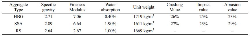
Materials
Ordinary Portland cement (OPC) (Grade 53) is used for testing. The physical and mechanical properties of the cement were tested according to IS: 4031-1988 and found to comply with the requirements of IS 12269-1987. The test uses Standard Zone II river sand (RS), 20 mm low-grade hard blue granite (HPG) aggregates of the Cauvery River Basin, Karur [13]. The physical and mechanical properties of the coarse aggregate and fine aggregate were determined according to IS 2386-1963 and confirmed with IS 383-1970. Class F Fly ash (FA) (Specific gravity 2.15) was obtained from Mettur Thermal power station confirms to IS 3812:2003, and silica fume (SF) (Specific gravity 2.25), obtained from M/s. ELKEM, Mumbai, confirms to IS 15388:2003. The above two are used as admixture minerals. A super plasticizer (SP) based on sulfonated naphthalene that confirms IS 9103-1999 is used as a chemical compound. SS Total (SSA) is manufactured by Coimbatore Steels Pvt. Ltd.; the main characteristics of the aggregates are given in Table 1.
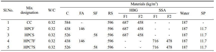
Tap water available in the laboratory in accordance with the requirements of IS: 456-2000 is used for mixing concrete and curing samples. Mix proportions are arrived as per ACI 211.4R-93, to obtain M60 grade concrete. Water cement ratio (W/C) and the cement content (C) are kept constant as 0.32 and 584 kg/m3 respectively for all mixes after extensive trials. Class F fly ash and silica fume are used as mineral admixtures at 25% and 10% of weight of cement respectively. Super plasticizer is used as chemical admixture at 2% of weight of cement as per IS 456-2000 to obtain required workability of concrete [14]. From literature it is observed that SS aggregates must be allowed to aging, before it is used in concrete as aggregates. According to Veerapathran & Murthi (2014), SS aggregates after 42 months of air aging [15] are used in the HPC mixes by fully replacing the HBG natural coarse aggregates to study the Flexural Behaviour of HPC Beams with SS Aggregate. Two fractions of coarse aggregates are used to obtain better grading. Fraction1-passing through 20mm and retained on 10 mm (F1), and fraction2-passing through 10mm and retained on 4.75m (F2) are used in this study. The aggregate types HBG and SSA are composed of 60% of fraction1 and 40% of fraction2 particles. The mix proportions considered are presented in Table 2.
Methods
Preparartion of beams
The Reinforced Concrete beams (RC beams) are designed as low reinforcement and have 2 bars with a diameter of 12 mm as the main reinforcement on the tension face and 2 bars with a diameter of 10 mm. Two feet 6 mm diameter strips are provided throughout the area at 100 mm intervals. The reinforcement profile of the beams tested for flexibility. The wooden mould is used for casting the beams. Mixed concrete is placed uniformly inside the mould and vibrated satisfactorily using needle vibrator. Beam specimens of size 100 × 200 × 2000 mm are cast with conventional concrete (CC), HPC made with conventional aggregates (HPCF and HPCS) and HPC made with SS aggregates after optimum aging period (HPC7F and HPC7S). After vibrating the entire concrete, the excess concrete at the top of the mould is struck off with a wooden straight edge and it is smoothly finished by trowelling. To find out the compressive strength of mixes, companion concrete cubes are also casted and tested as per IS516-1959 [28], along with beams. DE moulding is done after 24 hours and then covered with wet sacking to ensure proper curing. Prior to testing each beam is white washed to facilitate the observation of cracks during flexural testing.
Testing of beams
R.C beams are tested after 28 days, in the loading frame of capacity 1000 kN. The test specimens are placed in a simply supported condition and tested in loading frame under monotonic load only. All beam models are subjected to two-point loading and loads applied in increments of 5 kN. Dial gauges with a minimum of 0.01 mm are used to record the vertical deflection (Def) of the beam. They are placed on stands fitted with magnetic bases [16, 17]. Loaded with a 30-ton hydraulic jack, the load applied is measured using a ring with a capacity of 30 tons. All beams are loaded until they reach their full flexibility.
The nature of the beam is meticulously observed from beginning to end, until its collapse. Def’s are measured at the mid-section for every load increment. The load and Def at first crack is also noted. Crack patterns are marked with each load increase. Beams cannot be loaded until actual configuration failure due to exorbitant Def. In the final stage of loading, even if the hydraulic jack is activated, the load level does not increase. Although no structural failure occurs, functional failure certainly occurs at load, which is the ultimate load (UL).
The load Def characteristics, mode of failure, ductility and stiffness characteristics are studied in detail. Flexural behaviour of beams are analysed with simulations of the beams under static load conditions using finite element package ANSYS. Load carrying capacity and Def’s at mid span corresponding to the UL are compared with the experimental results for all types of beams.
Load-Deflection characteristics of HPC beams
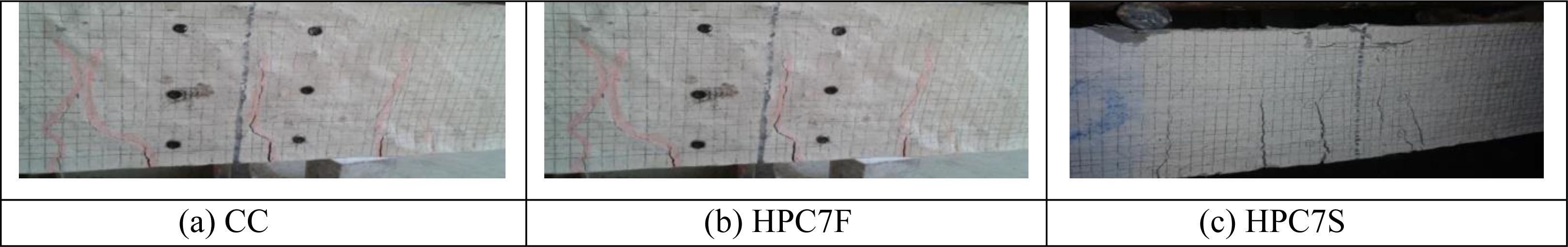
During the initial stage of mounting during the test the hair fracture develops in the lower part of the beam and as the loading continues, the crack expands and extends towards the neutral axis. The failure of all the beams tested occurs as a result of tension reinforcement, which then crushes the concrete in compression zone with ample caution before crash. Based on the test results, it can be seen that a significant increase in strength is felt at all load conditions with the addition of SS aggregates and mineral compounds such as fly ash and silica fume [18, 19]. The cracking pattern of the beam specimens after the flexibility test is shown in Fig. 1.
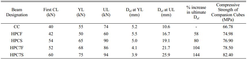
The first crack load (CL), yield load (YL), ultimate load (UL) and the corresponding mid span deflection (Def) values of tested beams along with compressive strength of companion cubes are presented in Table 3. The UL carrying capacity of HPC beams is found to be increasing when SS aggregates are used to replace the natural coarse aggregates [20, 21]. An increase in UL capacity and corresponding Def in all the HPC beams (except HPCF) is observed when compared to control beam (CC). The control beam showed a sudden failure after the YL. The first CL of control beam is lesser than that of all HPC beams.
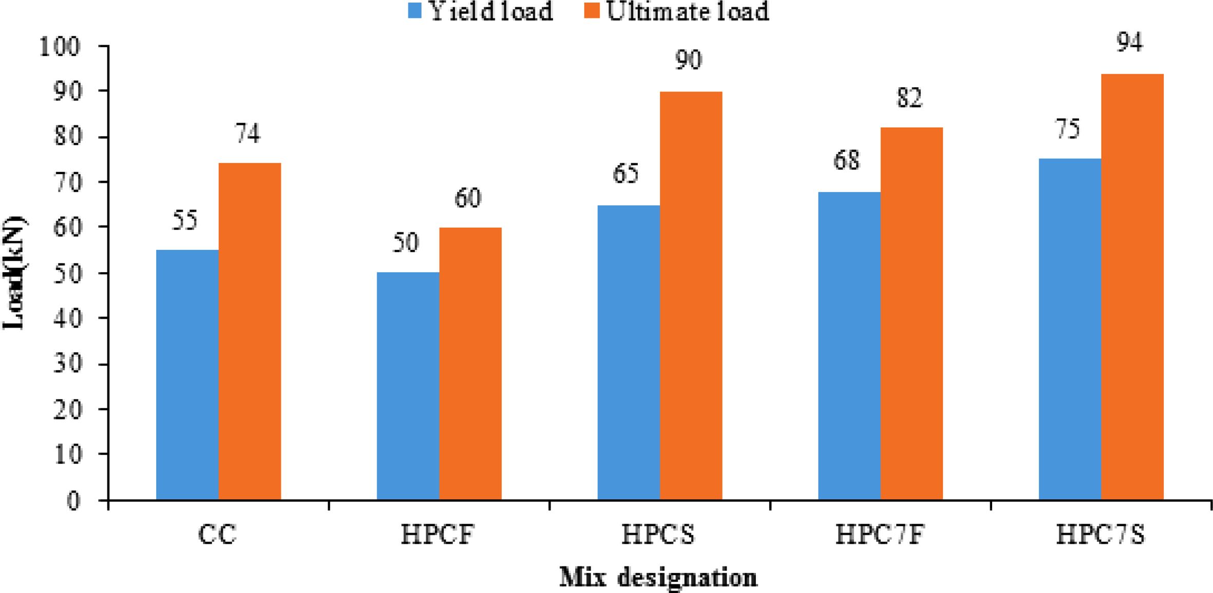
The YL of HPC beams are increased when SSA is added. From the results a gain of about 30% in the first CL, 24% in the YL and 16% in the UL for HPC7F beam is observed. Similarly a gain of about 50% in the first CL, 36% in the YL and 27% in the UL for HPC7S beam is observed. The significant increase in the UL may be due to the superior quality of SSA, better interlocking of SSA and cement paste and incorporation of fly ash/silica fume. From the compressive strength of companion cubes, it is clear that the quality of concrete is improved when the SSA and fly ash/silica fume are added into concrete. Hence more energy is required to propagate the crack path which results in increased load carrying capacity of beams. The comparison of YL and UL of beams made with CC and HPC mixes are given in Fig. 2.
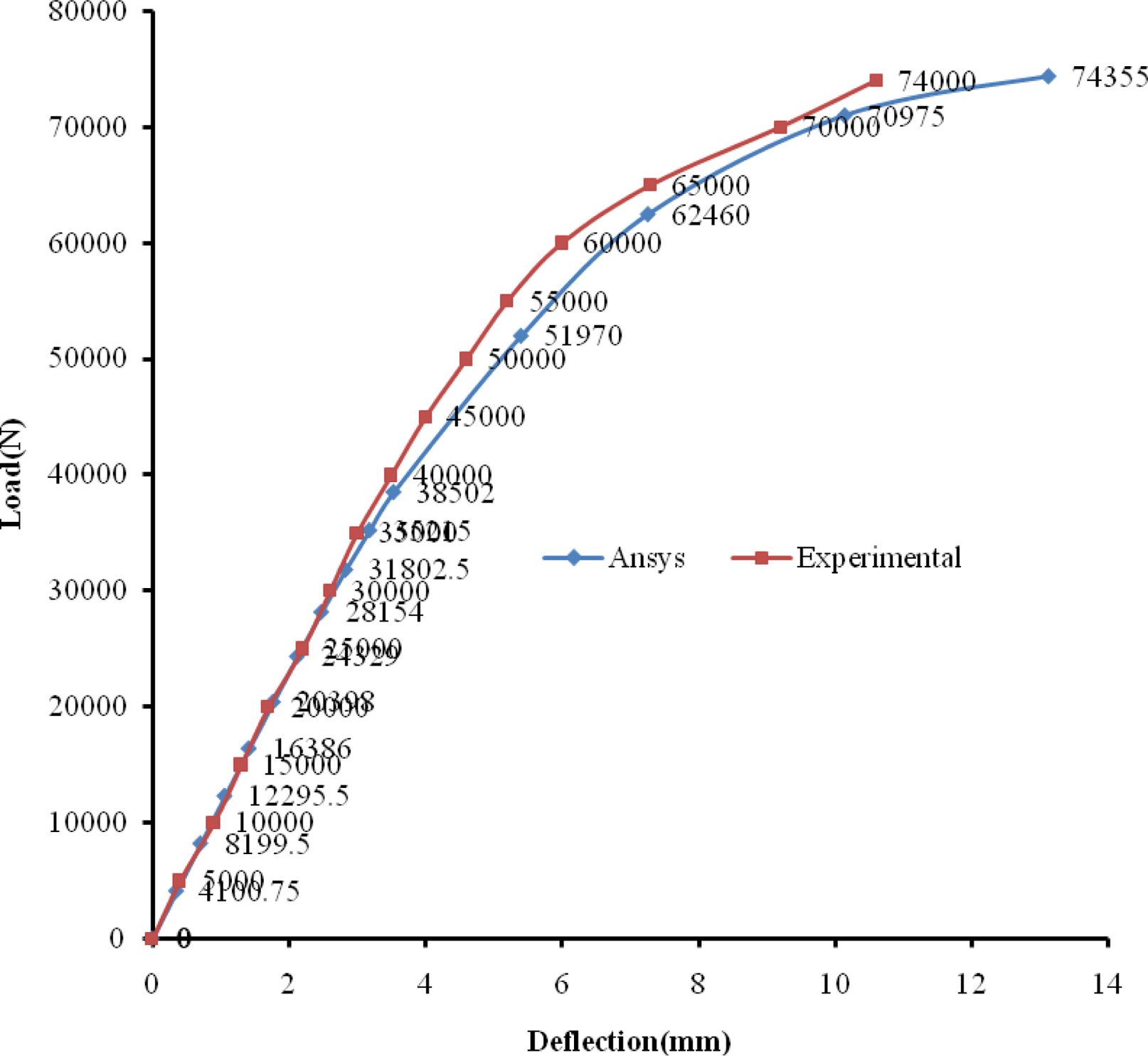
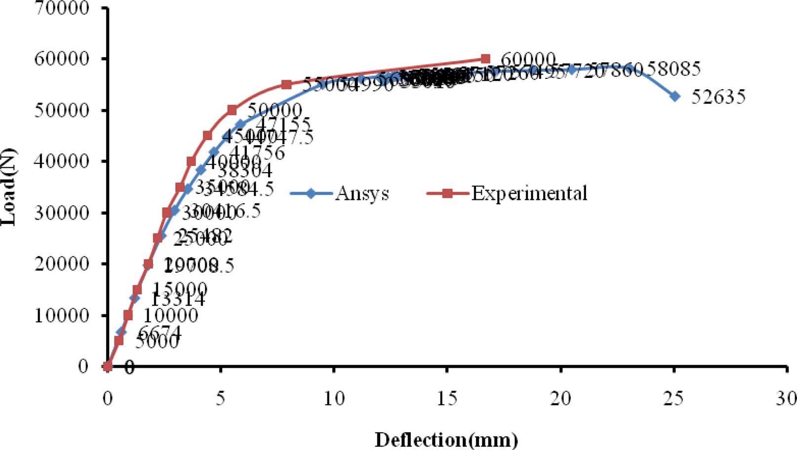
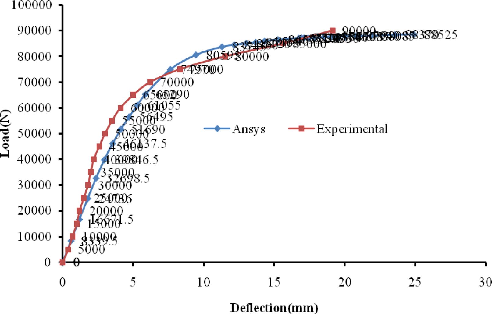
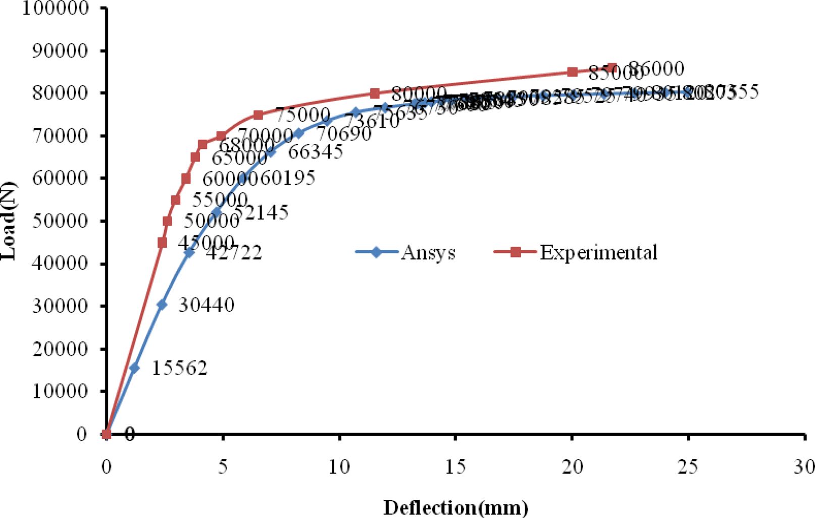
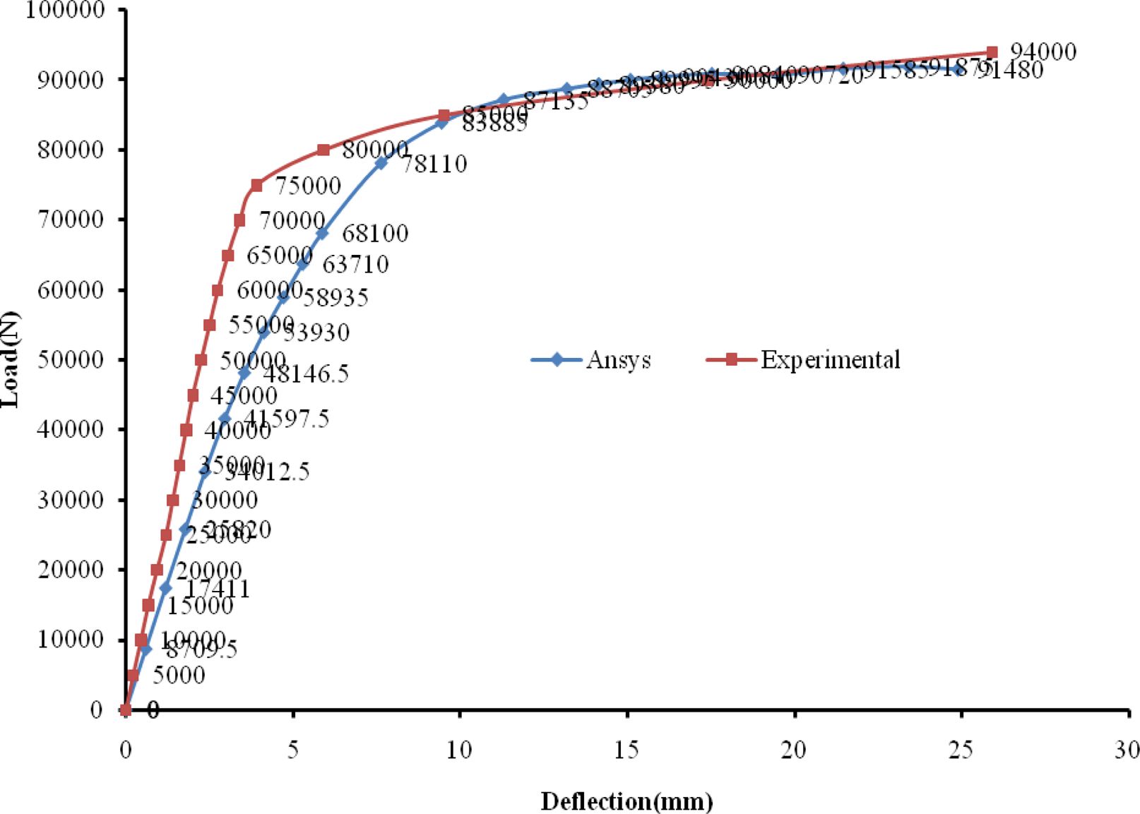
The load versus Def (at mid span) plots for the tested beams obtained by experimental and ANSYS analysis are presented from Fig. 3 to Fig. 7. From these Figures it is observed that there is no significant difference between experimental and analytical results. The test result shows that the Def at UL increases when SSA is added [22]. Fig. 4 Fig. 5 Fig. 6
An increase of about 104% in the ultimate Def of HPC7F beam is observed, when compared to control beam. Similarly an increase of about 144% in the ultimate Def of HPC7S beam is observed, when compared to control beam. Also, a decrease in Def at yield stage of about 21% is observed for HPC7F beam. Similarly a decrease in Def at yield stage of about 25% is observed for HPC7S beam.
Ductility of HPC beams
The ductility of reinforced concrete structures is very important because any member must withstand large Defs when carrying maximum loads and provide adequate caution before failure. It is measured by the ductility factor (ρ). It is the ratio of rotation (ω) or curvatures (ψ) or deflection (δ) is expressed for the failure of the property associated with the yield [23-25]. In this study, displacement ductility is explored, which is the final rate of yield Def and is calculated as shown in equation 1. Any kind of brittle failure should be avoided as it limits the alarm time. If the structure has flexible behaviour, it will experience large Def’s when holding ULs.
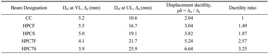
In general, a higher ductility rate indicates that a configuration member can make large Def’s before failure. The increase in deformations with the load decreases after reaching its maximum value is ignored during the test. Therefore in all calculations, deformations in UL are considered. Table 4 lists the values of displacement ductility [32-34].

Test results show that the presence of SS aggregates and admixtures in concrete influences the ductility. Compared to control beam, the ductility ratio is increased by 1.49 times for HPCF beam, 1.87 times for HPCS beam, 2.57 times for HPC7F beam and 3.25 times for HPC7S beam. This significant increase in ductility shows that SS aggregates and mineral admixtures have greater impact in the ductility behaviour of beams [26, 27].
It is fund that SS aggregate improves the ductility of HPC beams (HPC7F and HPC7S) compared to control beam and HPC beams with natural aggregates (HPCF and HPCS). The parameters responsible to the good ductility of the HPC beams (with SS aggregate, i.e. HPC7F and HPC7S) are the superior properties of the SS aggregate and the good bond between rough surfaced SS aggregate and paste [29, 30]. The energy absorbed is equal to the area under load Def curve. From Fig. 3 to Fig. 7 it can be realized that the energy absorption capacity of HPC beams are more when compared to the CC [31]. This significant increase in energy absorption capacity of HPC beams shows that SS aggregates and mineral admixtures improve the energy absorption capacity of HPC beams.
Stiffness of HPC beams
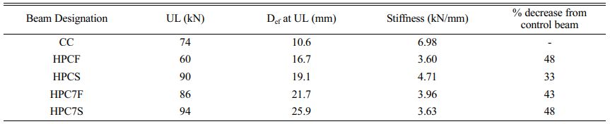
The ratio between UL and corresponding Def is calculated as stiffness of the beam specimens. The variation of stiffness with respect to control beam is shown in Table 5. It is observed that the stiffness of control beam is higher which shows a reduced ductility. When the SS aggregates and mineral admixtures are incorporated in the concrete, the stiffness of the HPC beams are reduced which results in the higher ductility of HPC beams [35, 36].
Comparison of Experimental results and ANSYS results
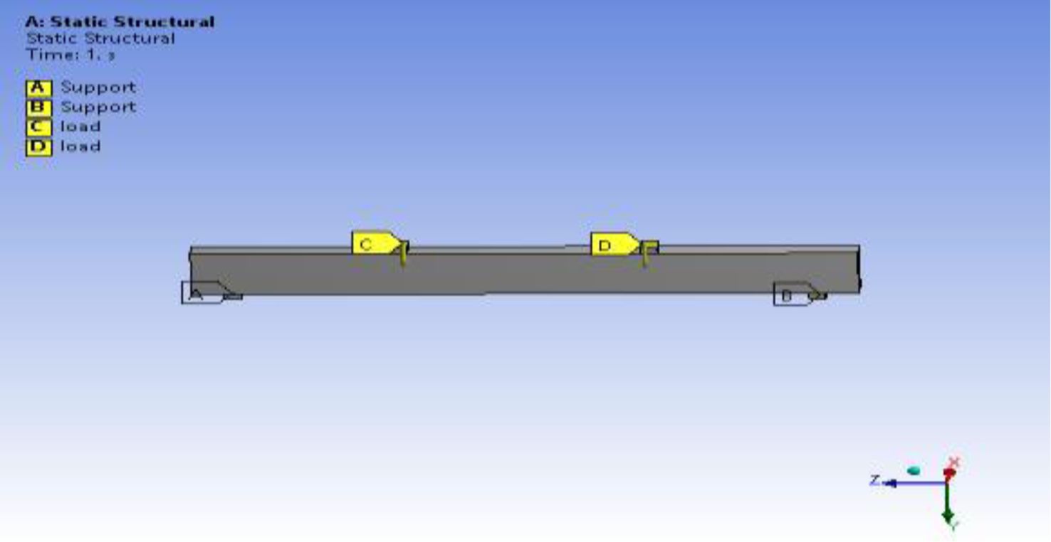
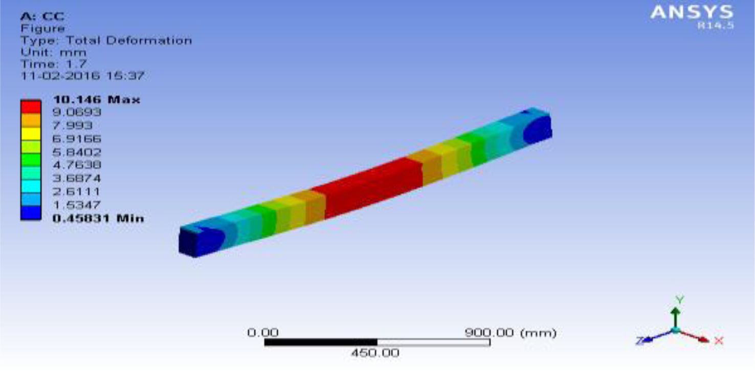
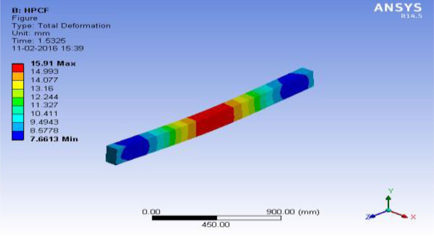
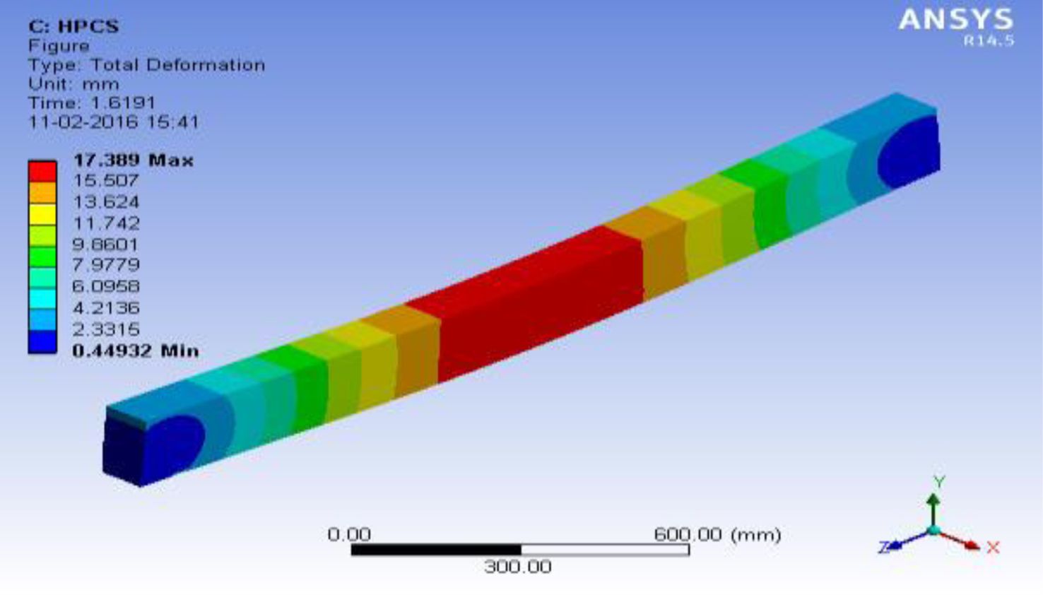
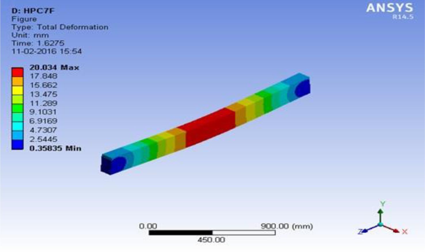
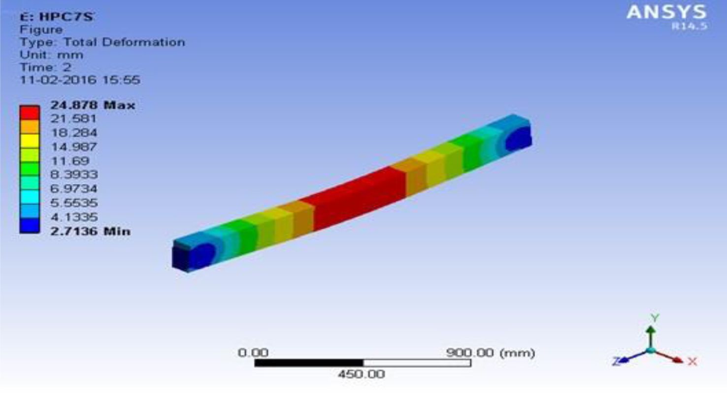
Figure 8 shows the ANSYS model of beam before loading. Figure 9 to Fig. 13 shows the Def pattern of the beams CC, HPCF, HPCS, HPC7F and HPC7S respectively. Fig. 10 Fig. 11 Figl. 12
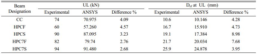
The various colours in the Figures indicate the range of Def at various points. Table 6 shows a comparison between results obtained from experimental investigation and ANSYS analysis on flexural behaviour of CC and HPC beams.
The difference in ULs obtained from experimental investigation and ANSYS analysis ranges from 2.68% to 4.57%. The difference in ultimate Def obtained from experimental investigation and ANSYS analysis ranges from 3.95% to 8.98%. From this table it is observed that there is a minimum difference exists between the experimental and analytical results are mainly due to the laboratory conditions and the accuracy of the equipment’s used for beam testing.
|
Fig. 1 Crack pattern of beam specimens after flexural test. |
|
Fig. 2 Comparison of yield and ULs of CC and HPC beams. |
|
Fig. 3 Load deflection plot of CC beam. |
|
Fig. 4 Load deflection plot of HPCF beam |
|
Fig. 5 Load deflection plot of HPCS beam |
|
Fig. 6 Load deflection plot of HPC7F beam. |
|
Fig. 7 Load deflection plot of HPC7S beam. |
|
Fig. 8 ANSYS model of beam |
|
Fig. 9 Deflection pattern of beam CC. |
|
Fig. 10 Deflection pattern of beam HPCF |
|
Fig. 11 Deflection pattern of beam HPCS. |
|
Fig. 12 Deflection pattern of beam HPC7F |
|
Fig. 13 Deflection pattern of beam HPC7S. |
From the results, the following conclusions are arrived.
1. All HPC beams (HPCF, HPC7F, HPCS and HPC7S) show better performance than control beam (CC). As UL capacity increases, the corresponding Def in all the HPC beams is observed when compared with CC.
2. The control beam shows a sudden failure after the YL. The first CL of CC beam is lesser than that of all HPC beams. From the results a gain of about 30% in the first CL, 24% in the YL and 16% in the UL for HPC7F beam is observed.
3. Similarly a gain of about 50% in the first CL, 36% in the YL and 27% in the UL for HPC7S beam is observed. The significant UL increase may be due to the superior quality of SSA, better interlocking of SSA, and cement paste and incorporation of fly ash/silica fume. Hence, more energy is required to propagate the crack path which results in increased load carrying capacity of beams.
4. The ductility ratio increases by 1.49 times for HPCF beam, 1.87 times for HPCS beam, 2.57 times for HPC7F beam and 3.25 times for HPC7S beam, while comparing with the control beam. This significant increase in ductility shows that SS aggregates and mineral admixtures play an important role in the ductility behaviour of beams.
5. It is observed that the stiffness of control beam is higher which shows a reduced ductility. When the SS aggregates and mineral admixtures are incorporated in the concrete, the stiffness of the HPC beams is reduced which results in the higher ductility of HPC beams.
6. The difference in UL obtained from test and ANSYS analysis, ranges from 2.68% to 4.57%. The difference in ultimate Def obtained from experimental investigation and ANSYS analysis ranges from 3.95% to 8.98%. From this table it is observed that there is a minimum difference exists between the experimental and analytical results are mainly due to the laboratory conditions and the accuracy of the equipment’s used for beam testing.
7. Overall, the flexural behaviour of HPC beams made with SS aggregate is found superior than the flexural behaviour of beams of CC/HPC made with Conventional aggregate.
The authors thank everyone who has contributed to improving the quality of this study.
The authors declare no competing interests.
All data generated or analysed during this study are included in this published article.
- 1. J.O. Akinmusuru, Res. Cons. and Recycl. 5[1] (1991) 73-80.
-

- 2. A.I. Al-Negheimish, F.H. Al-Sugair, and R.Z. Al-Zaid, J. King Saud Univ., Eng. Sci. 9[1] (1997) 39-54.
-
- 3. S.I. Ali, M.Sc. Thesis, King Fahd Univ. of Petroleum and Minerals, Saudi Arabia, 2003.
- 4. M. Maslehuddin, M. Alfarabi, M. Shameem, M. Ibrahim, and M.S. Barry, Constr. Build. Mater. 17[2] (2003) 105-112.
-
- 5. V.A. Akinbinu, Proc. of the 25th Int. Conf. on solid waste technology and management, March 14-17, Philadelphia, USA, 2010.
- 6. I. Netinger, M. Jelcic Rukavina, and D. Bjegovic, Gradevinar. 62[1] (2010) 35-43.
- 7. I. Netinger, D. Bjegovic, D. Varevac, and D. Moric, Gradevinar. 63[2] (2011) 169-175.
- 8. K.S. Ali, N.M. Ishak, and A.R.M. Ridzuan, Proc. of the IEEE Symp. on Business, Eng. and Ind. Applications, Malaysia (2011) pp. 570-575.
-
- 9. G. Adegoloye, A.L. Beaucour, S. Ortola, and A. Noumowe, Proc. of the 3rd Int. Slag Valorisation Symp. (2013) pp. 351-354.
- 10. S.A. Tarawneh, E.S. Gharaibeh, and F.M. Saraireh, Am. J. App. Sci. 11[5] (2014) 700-706.
- 11. J. Song, X. Yang, P. Chen, H. Xu, D. Luo, and R. Lai, J. Ceram. Process. Res. 23[4] (2022) 409-414.
-
- 12. M. Verapathran and P. Murthi, Gradevinar. 66[7] (2014) 605-612.
- 13. R. Sivabalan, K.R. Thangadurai, and K. Lenin, J. Ceram. Process. Res. 22[6] (2021) 605-614.
-
- 14. IS4031:1988, Method of physical test for hydraulic cement, BIS, New Delhi, India.
- 15. R. Girimurugan, J. Bensamraj, and S. Karthick, J. Ceram. Process. Res. 23[4] (2022) 553-557.
-
- 16. IS12269:1987, Specification for 53 Grade Ordinary Portland Cement, BIS, New Delhi, India.
- 17. S. Srikanth, A. Parthiban, M. Ravikumar, and K. Vignesh, J. Ceram. Process. Res. 23[4] (2022) 523-528.
-
- 18. IS 2386:1963, Methods of test for aggregates for Concrete, BIS, New Delhi, India.
- 19. IS 383:1970, Specification for coarse and fine aggregates from natural sources for concrete, BIS, New Delhi, India.
- 20. E.-H. Kim, G.-H. Cho, H.-Y. Park, H.-H. Choi, and Y.-G. Jung, J. Ceram. Process. Res. 22[1] (2021) 1-7.
-
- 21. IS 3812:2003, Specification for pulverized fuel ash Part 2: For use as admixture in cement mortar and concrete, BIS, New Delhi, India.
- 22. R. Thirumalai, S. Karthick, and M. Giriraj, J. Ceram. Process. Res. 23[2] (2022) 221-227.
-
- 23. IS 15388:2003, Silica fume – Specification, BIS, New Delhi, India.
- 24. IS 9103:1999, Specification for admixtures for concrete, BIS, New Delhi, India.
- 25. IS 456:2000, Code of practice for Plain and Reinforced Concrete, BIS, New Delhi, India.
- 26. ACI 211.4R-93, Guide for selecting proportions for High Strength concrete with Portland Cement and fly ash, ACI Committee 211, ACI, Detroit, USA.
- 27. K.-H. Lin, Y.-T. Tsai, and K.-L. Wang, J. Ceram. Process. Res. 21[1] (2020) 103-112.
-
- 28. IS 516:1959, Methods of tests for strength of concrete, BIS, New Delhi, India.
- 29. M. Verapathran and P. Murthi, Int. J. Chem. Sci. 14[2] (2016) 1015-1025.
- 30. T. Nithyanandhan and R. Ramamoorthi, J. Ceram. Process. Res. 22[4] (2021) 369-376.
-
- 31. M. Veerapathran, S. Arnesh, M. Kishore Kumar, S. Rakeshwaran, and A. Sarankarthi, Mater. Res. Proceedings 19 (2021) 161-165.
-
- 32. S. Vivek, J. Robinson, T.-T. Ranjith, and A. Naveen, Int. J. ChemTech. Res. 10[8] (2017) 605-622.
- 33. A. Subbaiyan, S.R. Murugesan, M. Shanmugamoorthy, V. Sivakumar, P. Velusamy, S. Veerasamy, K. Mani, P. Sundararaj, and S. Periyasamy, Adv. Mater. Sci. and Eng. Article ID 3906256, Special Issue, vol. 2022, p-7.
- 34. Z. Li, X. Zhang, G. Ma, R.A. Muvunyi, and D. Zheng, J. Ceram. Process. Res. 23[3] (2022) 344-349.
-
- 35. J.G. Park, Y.S. Choi, and I.J. Kim, J. Ceram. Process. Res. 22[3] (2021) 301-305.
-
- 36. M. Palpandi and G. Magudeeswaran, J. Ceram. Process. Res. 22[5] (2021) 527-537.
-
 This Article
-
2023; 24(1): 89-97
Published on Feb 28, 2023
- 10.36410/jcpr.2023.24.1.89
- Received on Jun 29, 2022
- Revised on Sep 26, 2022
- Accepted on Oct 26, 2022
Services
- Abstract
introduction
materials and methods
results and discussion
conclusion
- Acknowledgements
- Conflict of Interest
- Availability of data and materials
- References
- Full Text PDF
Shared
Correspondence to
- M. Verapathran
-
Department of Civil Engineering, Dr, N.G.P. Institute of Technology, Coimbatore-641048, India
Tel : +917373265444 Fax: +0422-2369106 - E-mail: mveerapathran@gmail.com
Clean-Energy Research Institute(CRI), Hanyang University, 222, Wangsimni-ro, Seongdong-gu, Seoul, 04763, Korea
E-mail: jcpr@hanyang.ac.kr