


- Synthesis of boron carbide powder through gas-solid reaction method using nanoporous carbon as carbon source
Haozhan Lia, Hongkang Weia,*, Huijuan Qiua, Yukang Wanga, Chang-an Wangb and Zhipeng Xieb
aAdvanced Ceramic Materials Research Institute, School of Materials Science and Engineering, Jingdezhen Ceramic University, Jingdezhen, Jiangxi 333401, People’s Republic of China
bState Key Laboratory of New Ceramics and Fine Processing, School of Materials Science and Engineering, Tsinghua University, Beijing 100084, People’s Republic of ChinaThis article is an open access article distributed under the terms of the Creative Commons Attribution Non-Commercial License (http://creativecommons.org/licenses/by-nc/4.0) which permits unrestricted non-commercial use, distribution, and reproduction in any medium, provided the original work is properly cited.
Sub-micron boron carbide powders were synthesized through a gas-solid reaction process using ZIF-8-derived nanoporous carbon and boron oxide as raw materials. The effects of calcination temperature and atmosphere, amount of boron oxide, and gas-solid reaction apparatus on phase composition and morphology of the synthesized boron carbide powders were studied. The results show that, even with sufficient boron oxide addition, it is not feasible to obtain boron carbide powder of high purity in argon environment. Although vacuum environment can significantly improve the purity of the synthesized boron carbide powder, there are a large number of large particles of step morphology in the synthesized boron carbide powder. The improved gas-solid reaction apparatus can effectively impede the formation of boron carbide particles of step morphology. Nearly spherical submicron boron carbide particles with a median particle size of 480 nm and good particle size consistency could be synthesized at 1600 °C with 0.3 g nanoporous carbon and 10 g B2O3 under vacuum by using the improved apparatus
Keywords: Boron carbide, Gas-solid reaction method, Carbothermal reaction, Nanoporous carbon, Particle size distribution
Boron carbide (B4C) is one of the most potential ceramics widely used in many important fields such as military protective armor, abrasive industry, and nuclear industry due to its high hardness and melting point, excellent wear resistance, low density, stable chemical durability, and good neutron absorption property [1-5]. Zhang and Moshtaghioun found that boron carbide ceramic products with ultra-high hardness and excellent fracture toughness could be prepared using ultra-fine boron carbide powder and spark plasma sintering process, in which, the access of boron carbide powder with high purity, ultra-fine, and uniform particle size is one of the deciding factors [6, 7].
Nowadays, several processing routes are available to synthesize boron carbide, including carbothermal reduction [8-10], self-propagating high-temperature synthesis [11], laser-induced chemical vapor deposition [12], sol-gel [13], and microwave synthesis [14, 15] methods, among which carbothermal reduction method is most commonly used in industry. Generally, in a traditional carbothermal reduction process, inorganic carbon sources and boron sources (H3BO3 or B2O3) were first mixed, and thereafter calcined in a vacuum furnace. The particle size of the boron carbide powder synthesized through this process was often scattered and in the micrometer range [16], possibly due to the uneven mixing of the raw materials and poor reaction activity. To obtain ultra-fine boron carbide powder with better morphology, much emphasis has been placed on synthesizing boron carbide powders using organic carbon sources such as sucrose and cellulose [17-20]. However, in most cases, the synthesis of boron carbide powder with fine particle size and uniform morphology was not realized.
Nanoporous carbon (NPC) derived from the pyrolysis of zeolitic imidazolate frameworks (ZIFs) has the advantages of high specific surface area, fine and monodisperse particle size, and stable crystal structure. It has been widely used in adsorbents, drug transport carriers, catalyst carriers, battery electrodes, and supercapacitors [21-26]. Similarly, on account of its excellent performance, it becomes a potential carbon source in the synthesis of ultrafine boron carbide powders with mono-size distribution.
In addition to broadening carbon sources, the gas-solid reaction process has also been applied in the synthesis of carbide powders and nanowires [27-29]. When using the gas-solid reaction method to synthesize ceramic powder, there is no need to mix raw materials in advance, that is, the reactants were placed separately. During the calcination process, one of the reactants volatilized into the gas phase, and then diffused among and contacted with other solid reactants to realize the reaction. The absence of the blending procedure, as well as the coating of the gas phase onto the solid-phase particles resulting in an increase in the contact between the reactants, are presumably conducive to obtaining boron carbide powder of fine and uniform particle size.
In this paper, boron carbide powders were synthesized using the gas-solid reaction process with NPC as the carbon source and boron oxide as the boron source. During this gas-solid reaction process, NPC particles, due to their nanoporous structure and high specific surface area, are able to adsorb more boron oxide vapors, potentially promoting the chemical reaction between the carbon source and boron oxide. The effects of calcination temperature and atmosphere, amount of boron oxide, and different gas-solid reaction apparatuses on the phase evolution and microscopic morphology of the synthesized powder were studied.
Preparation of ZIF-8 and NPC
Zinc nitrate hexahydrate (Zn(NO3)2·6H2O, 99%), 2-Methylimidazole (Hmim, 98%), methanol (99.5%), and boron oxide (99%) used in this experiment were all purchased from Sinopharm Chemical Reagent.
ZIF-8 was synthesized by a thermal solvent method [30]. Zn(NO3)2·6H2O and Hmim were separately dissolved into methanol with ultra-sonication to form two clear solutions. The two solutions were heated to 60 °C in a water bath. After the temperature of the solutions became stable by stirring for 30 min, the zinc solution was poured into the Hmim solution and was stirred for 1 h at 60 °C. Then, the milky solution was kept at room temperature and aged for 23 h. The synthesized white precipitate was isolated by centrifugation (10000 rpm, 10 min) and washed using methanol three times. Finally, the ZIF-8 powder was obtained after drying at 100 °C overnight. NPC was prepared by the carbonization of the as-prepared ZIF-8 powder under a stream of argon gas flow at 850 °C for 6 h with a heating rate of 5 °C/min.
Synthesis of boron carbide powder through gas-solid reaction
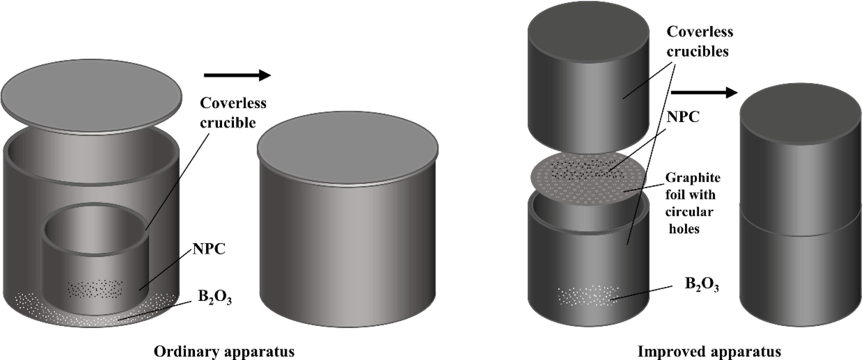
Figure 1 illustrates the two gas-solid reaction apparatuses used to synthesize boron carbide. In the case of the ordinary apparatus, two graphite crucibles of different diameters were adopted. The coverless crucible charged by the carbon source was placed in the other crucible of larger diameter. After putting the boron source on the bottom of the larger crucible, a suitable lid was placed at the opening of the larger crucible. The purpose of the improved apparatus is to enhance the reaction efficiency. This apparatus involves two coverless graphite crucibles of the same diameter. The two crucibles were stacked in opposite directions. A piece of graphite foil, among which holes of 0.5 mm diameter were regularly distributed, was sandwiched between the two crucibles. The NPC particles were slightly placed on the graphite foil and reacted with the boron oxide vapor that passed through the graphite foil during the calcination process.
After being charged with NPC and boron oxide, the apparatuses were heated to the selected temperature with a heating rate of 15 °C/min and a 1 h dwell time under vacuum or argon (as shown in Table 1), accompanied by the following reaction:

For both apparatuses, since the graphite crucibles are not completely sealed, the unreacted boron oxide vapor and the CO gas generated by the reaction escaped from the apparatuses and finally exited the furnace.
Characterization and analytical methods
The phase composition of the synthesized powder was determined by x-ray diffraction analysis (XRD, D8, Bruker, Germany). The morphology and structure of the obtained particles were observed by scanning electron microscope (SEM, SU8010, Hitachi, Japan) and transmission electron microscope (TEM, JEM-2010HR, JEOL, Japan). A minimum of 200 particles per specimen were measured to determine the particle size distribution using ImageJ software.
|
Fig. 1 Diagram of the two different apparatuses used to synthesize boron carbide. |
Phase and morphology characterization of ZIF-8 and NPC
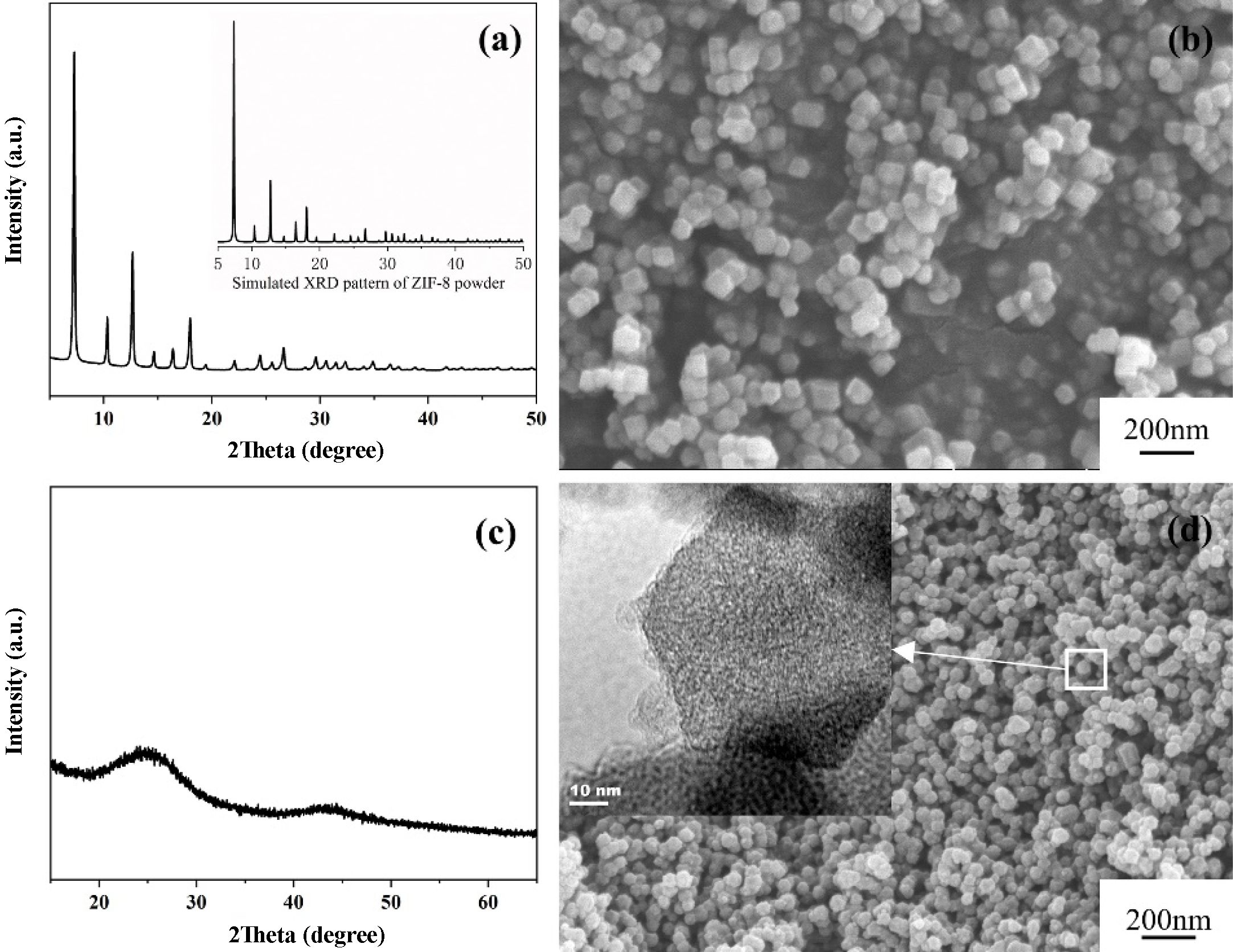
Figure 2 illustrates the phase and microstructure of the ZIF-8 powder and NPC powder. Fig. 2(a) shows the XRD pattern of the synthesized ZIF-8 powder, which is consistent with the simulated pattern of single-phase ZIF-8 [31]. The ZIF-8 powder exhibits a typical rhombic dodecahedron morphology with a uniform particle size of 90 nm (Fig. 2(b)). As seen from Fig. 2(c), the two wide and humped diffraction peaks at 25° and 44° are related to the facets of (002) and (100) in the typical graphitic carbon respectively, suggesting that ZIF-8 totally carbonized after the heat treatment by the vaporization of Zn [31]. It is obvious that, as shown in Fig. 2(d), the NPC particles inherited the original shape of ZIF-8, only with a bit reduction in diameter (from 90 nm to 50 nm). In addition, the TEM image of NPC (the inset of Fig. 2(d)) shows that the NPC that derived from ZIF-8 could still preserve the nanoporous morphology.
Effects of calcination temperature and amount of boron oxide on the phase of the synthesized powders
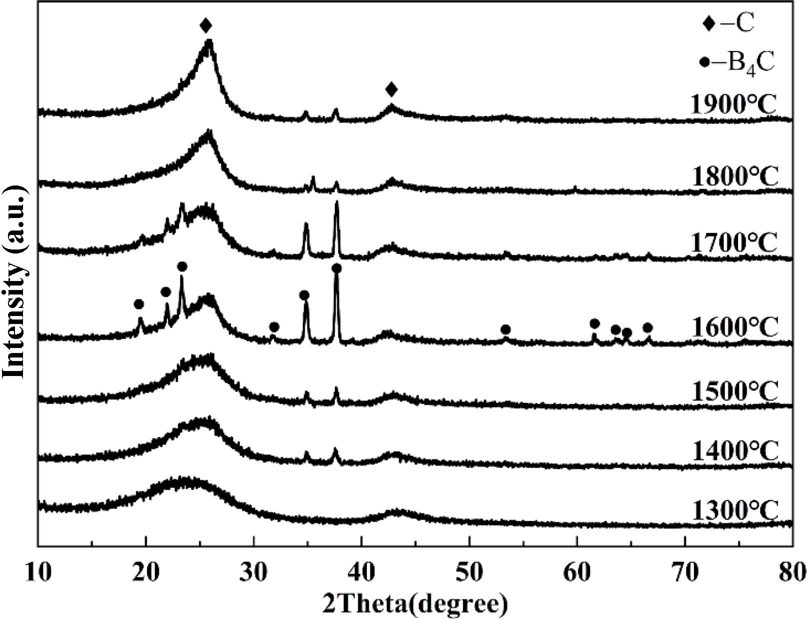
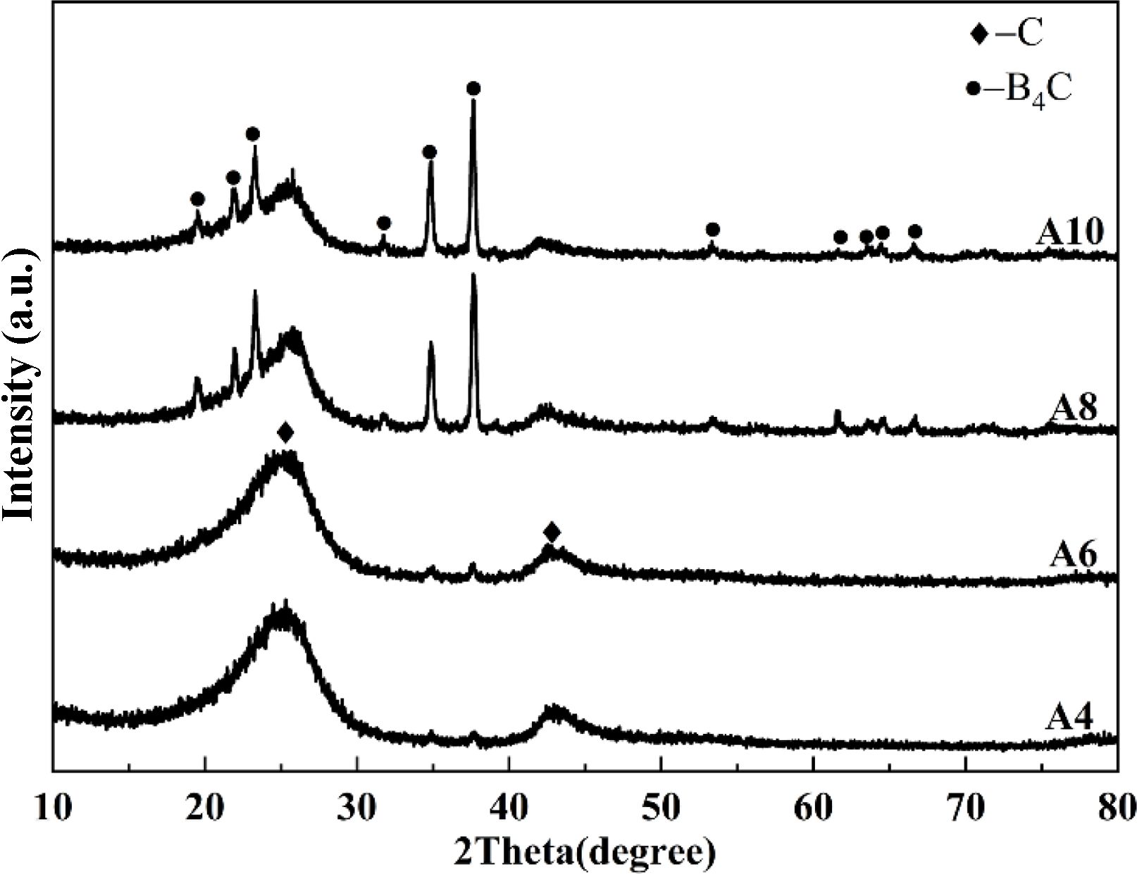
Figure 3 shows the XRD patterns of the powders from sample A8 calcined at various temperatures. The XRD pattern of the powder calcined at 1300 °C is consistent with that of NPC (Fig. 2(c)), indicating that the carbothermal reduction reaction between NPC and boron oxide vapor did not occur at 1300 °C. When the calcination temperature rose to 1400 °C, the boron carbide phase began to appear in the reaction product. With the increase of the calcination temperature, the proportion of boron carbide phase in the synthesized product gradually increased and reached the maximum at 1600 °C (still containing residual NPC). It is noteworthy that the content of the residual NPC phase increased obviously in the powders synthesized at temperatures higher than 1600 °C, probably related to the significantly increased loss of boron oxide before participating in the reaction.
According to formula (1), in the case of the complete chemical reaction, only 0.5 g boron oxide is needed to consume 0.3 g NPC. The effect of the amount of boron oxide on the phase composition of the synthesized powder is shown in Fig. 4. The main phase, NPC, along with a trace of boron carbide could be detected in the powders synthesized in argon at 1600 °C when the amount of boron oxide is 4 g and 6 g. This indicates that only a small part of the volatilized boron oxide vapor participated in the carbothermal reduction reaction during the calcination process. By further increasing the boron oxide amount, the content of boron carbide in the product increased significantly. However, since the phase compositions of the A8 and A10 (calcined at 1600 °C in argon) are similar, it can be concluded that, although more boron oxide contributed to the formation of the boron carbide phase, boron carbide of high purity cannot be obtained by adjusting the calcination temperature and boron oxide amount in argon environment using the ordinary-type apparatus.
Influence of calcination atmosphere on the phase of the synthesized powders
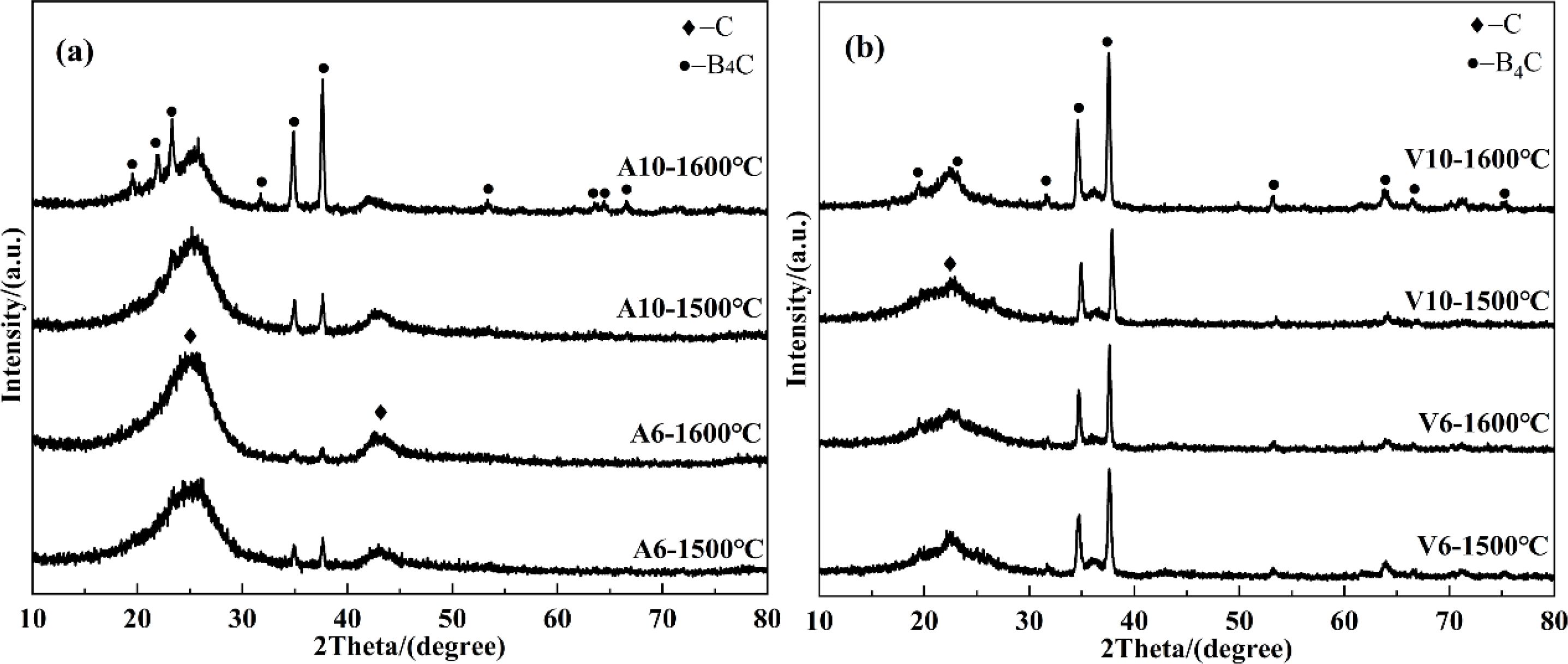
It can be seen from Fig. 5 that, compared with the argon environment (Fig. 5(a)), the vacuum environment (Fig. 5(b)) predominantly facilitated the formation of the boron carbide phase. As mentioned above, in argon environment, the boron carbide phase could be substantially generated only when the amount of boron oxide exceeded 8 g (Fig. 4), while the synthesized powder with the main phase of boron carbide could be obtained with 6 g boron oxide under vacuum (Fig. 5(b)). According to the XRD patterns of the synthesized powders from V6 and V10 at 1500 °C in Fig. 5(b), the synthesis temperature of boron carbide of high purity could be reduced to 1500 °C in vacuum, while by contrast, in argon environment, only powders with boron carbide as the main phase (containing a fraction of residual NPC) could be obtained above 1600 °C, even with sufficient boron oxide addition. There are two reasons for the superiority of vacuum environment over argon environment in the formation of the boron carbide phase: (1) When synthesizing boron carbide in argon, the argon in the reaction crucible significantly reduced the concentration of the volatilized boron oxide vapor, which impeded the carbothermal reduction reaction. (2) The vacuum environment could effectively increase the discharge rate of CO gas (reaction product), which was more favorable for the chemical reaction to proceed in the direction of synthesizing boron carbide. In addition, it should be noted from Fig. 5(b), that except for sample V10 at 1600 °C, the other three samples have relatively obvious broad diffraction peaks in the 2θ range of 17-30°, indicating the existence of a trace amount of residual NPC.
Effect of gas-solid reaction apparatus on phase and morphology of the synthesized powders
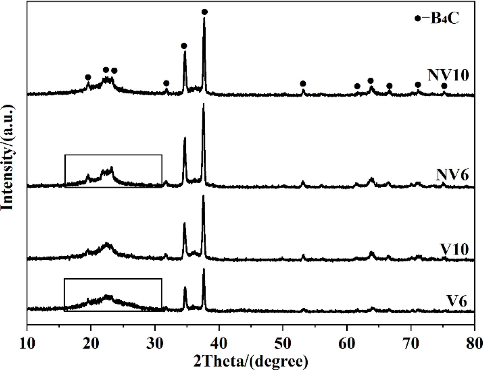
When the improved gas-solid apparatus was applied, the volatilized boron oxide vapor passed through the graphite foil via the holes and then reacted with the NPC. The guiding effect of the improved gas-solid apparatus for boron oxide vapor improved the efficiency of the chemical reaction. As a result, in comparison with V6 and V10 calcined at 1600 °C, the low angle diffraction peaks (17-25°) of the boron carbide phase in the NV6 and NV10 samples synthesized at the same temperature are slightly sharper (Fig. 6). Moreover, by analyzing the diffraction peaks marked with black rectangular boxes, it could be found that, unlike the V6 sample at 1600 °C, the NV6 sample had no obvious broad peak in the range of 17-30° assigned to NPC.
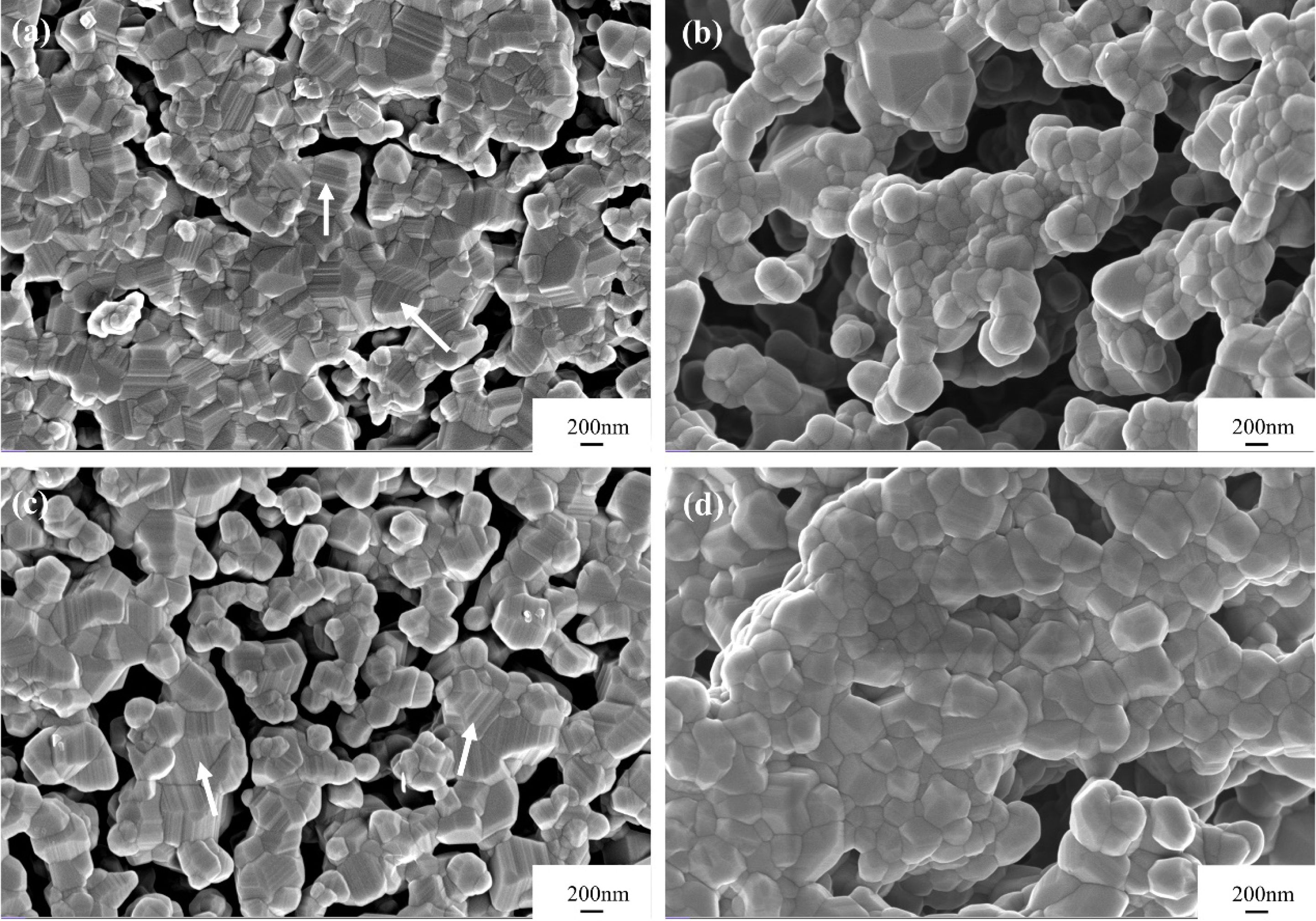
The traditional synthesis method (containing the blending procedure of boron and carbon sources) could not achieve complete and uniform mixing of the raw powders, resulting in the local excess of boron or carbon sources. Therefore, particles of residual boron and carbon sources often appeared in the synthesized powders. In addition, rod-like particles, as well as boron carbide nanobelts and nanowires were often found in the synthesized powders [16, 17]. In contrast, the morphology uniformity of the boron carbide powders synthesized by the gas-solid reaction method is better (Fig. 7). As shown in Figs. 7(a) and 7(c), in addition to the boron carbide particles with small particle size and near-spherical morphology, there are also boron carbide particles of larger particle size and step morphology (marked with white arrows). It is possible that during the calcination process in the ordinary apparatus, the volatilized boron oxide vapor first rose to the lid of the graphite crucible, and then diffused into the small crucible filled with NPC to enable the carbothermal reduction reaction to proceed. Due to the long diffusion path of the boron oxide vapor in the ordinary-type device, the continuity of the contact between the NPC particles and the boron oxide vapor tended to be interrupted, resulting in the discontinuity of the chemical reaction and the resultant step morphology. Furthermore, the discontinuity of this chemical reaction was more serious with less amount of boron oxide, which led to a higher proportion of boron carbide particles of step morphology in the synthesized powder with 6 g boron oxide addition than that of 8 g. Different from the ordinary apparatus, in the improved apparatus, the diffusion path of the boron oxide vapor into the NPC powder was much smoother and oriented, which resulted in better reaction continuity and effectively avoided the formation of particles of step morphology. Thus, as shown in Figs. 7(b) and 7(d), boron carbide particles of step morphology could rarely be detected in powders synthesized in the improved apparatus. Moreover, by comparing the morphologies of the powders involved in Fig. 7, the particle size consistency was promoted by using the improved apparatus, among which the NV10 powder calcined at 1600 °C exhibited the best particle size uniformity.
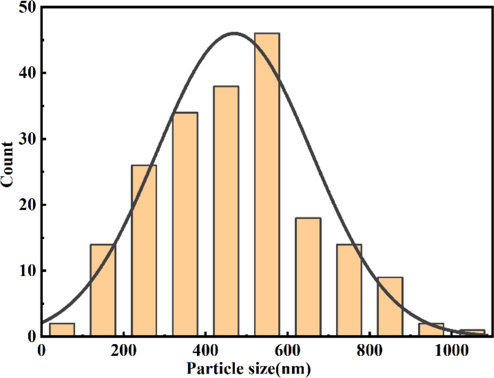
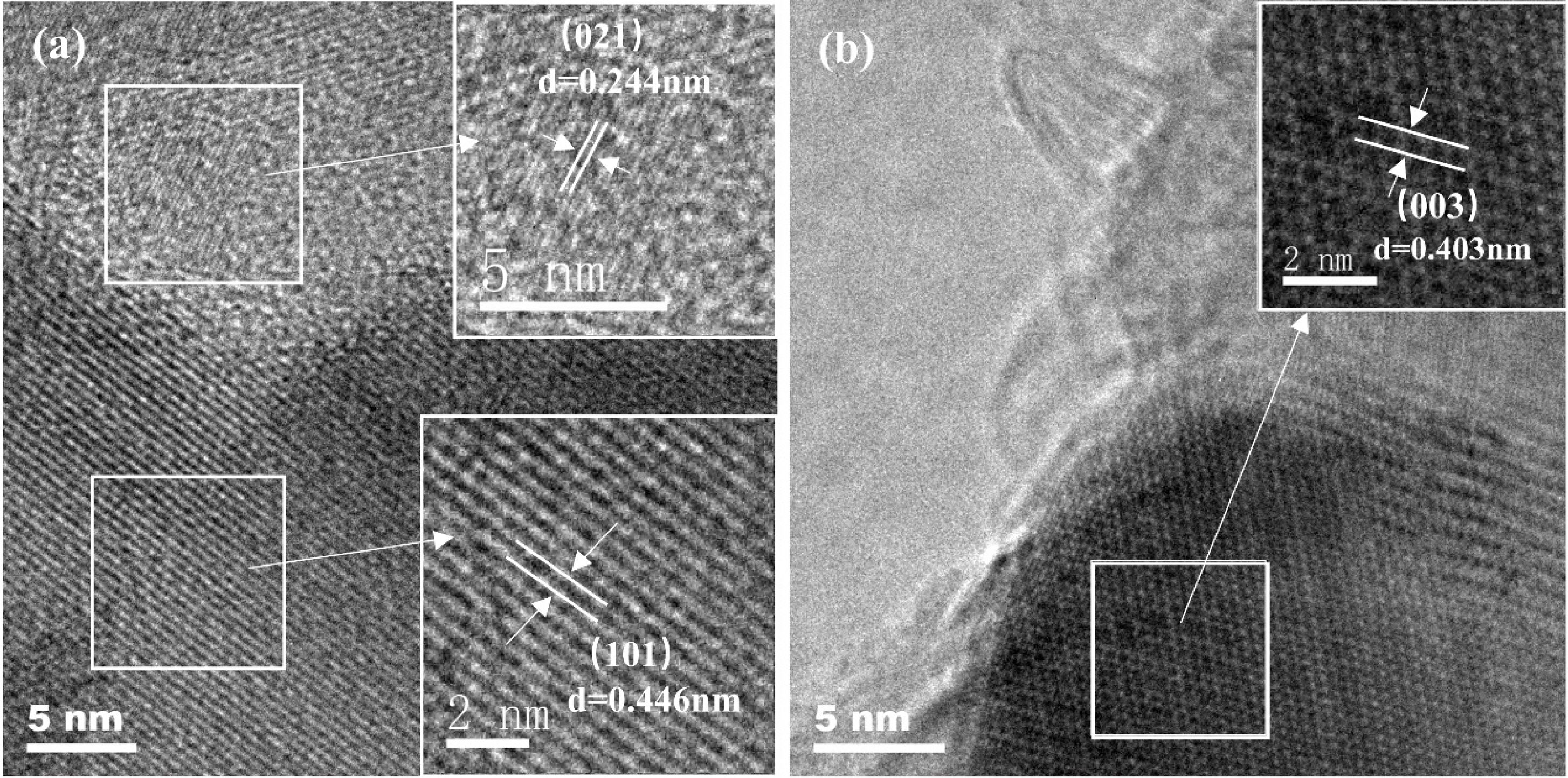
The statistical particle size distribution of NV10 at 1600 °C was analyzed by SEM image with the aid of ImageJ software. As shown in Fig. 8, the particle size is basically fitted to the normal distribution, and the median particle size is about 480 nm. Fig. 9 shows the high-resolution TEM images of the NV10 powder synthesized at 1600 °C, where the lattice fringe spacings of 0.244, 0.446, and 0.403 nm correspond with the (021), (101), and (003) lattice planes of boron carbide, respectively.
|
Fig. 2 The XRD patterns and morphologies of ZIF-8 powder and ZIF-8-derived NPC powder: (a) and (b) ZIF-8, (c) and (d) ZIF-8 derived NPC powder, and the inset showing an additional TEM micrograph of NPC powder. |
|
Fig. 3 XRD patterns of A8 synthesized at 1300-1900 °C. |
|
Fig. 4 XRD patterns of the synthesized powders in argon environment at 1600 °C. |
|
Fig. 5 XRD patterns of powders synthesized using the ordinary apparatus in (a) argon and (b) vacuum environment. |
|
Fig. 6 XRD patterns of the powders synthesized at 1600 °C in vacuum using two different apparatuses. |
|
Fig. 7 SEM images of the powders synthesized at 1600 °C in vacuum using two different apparatuses: (a) V6, (b) NV6, (c) V10, and (d) NV10. |
|
Fig. 8 Statistical particle size distribution of NV10 calcined at 1600 °C. |
|
Fig. 9 High-resolution TEM images of NV10 calcined at 1600 °C. |
Submicron boron carbide powder with nearly spherical shape and good particle size consistency was synthesized with NPC as carbon source through gas-solid reaction method.
(1) The environmental atmosphere has a significant effect on the synthesis of boron carbide. It is hard to obtain the boron carbide powder of higher purity in argon environment. Compared with the argon environment, the vacuum atmosphere can significantly increase the purity of the boron carbide phase in the synthesized powder.
(2) In the gas-solid reaction synthesis of boron carbide, the reaction apparatus affects the volatilized boron oxide vapor flow characteristics so as to affect the synthesis of boron carbide. In comparison with the ordinary gas-solid reaction apparatus, the boron carbide powder synthesized with the improved gas-solid apparatus presents higher purity, nearly spherical morphology, and better particle size consistency.
(3) Boron carbide powder with the median particle size of 480 nm was obtained under vacuum at 1600 °C with 10 g boron oxide and 0.3 g NPC.
The authors gratefully acknowledge the financial support from the National Natural Science Foundation of China (Grant No. 51662018), the Hundred People Oceangoing Voyage Project of Jiangxi Province, and the Jiangxi Provincial Postgraduate Innovation Fund (Grant No. YC2020-S421).
- 1. S. Ebrahimi, M.S. Heydari, H.R. Baharvandi, and N. Ehsani, Int. J. Refract. Met. H. 57 (2016) 78-92.
-

- 2. W. Zhang, S. Yamashita, and H. Kita, Adv. Appl. Ceram. 118 (2019) 222-239.
-
- 3. F. Thévenot, J. Eur. Ceram. Soc. 6 (1990) 205-225.
-
- 4. P. Švec, J. Ceram. Process Res. 20 (2019) 113-120.
-
- 5. H.K. Wei, Y.J. Zhang, and X.Y. Deng, J. Ceram. Process Res. 12 (2011) 599-601.
-
- 6. X.R. Zhang, Z.X. Zhang, Y. Sun, M.Y. Xiang, G.S. Wang, Y.M. Bai, J.B. Mu, H.W. Che, and W.M. Wang, J. Alloy. Compd. 762 (2018) 125-132.
-
- 7. B.M. Moshtaghioun, A.L. Ortiz, D. Gómez-García, and A. Domínguez-Rodríguez, J. Eur. Ceram. Soc. 35 (2015) 1991-1998.
-
- 8. Y.M.Z. Ahmed, S.M. El-Sheikh, E.M.M. Ewais, A.A. Abd-Allah, and S.A. Sayed, J. Mater. Eng. Perform. 26 (2017) 1444-1454.
-
- 9. A. Alizadeh, E. Taheri-Nassaj, N. Ehsani, and H.R. Baharvandi, Adv. Appl. Ceram. 105 (2013) 291-296.
-
- 10. A. Alizadeh, E. Taheri-Nassaj, and N. Ehsani, J. Eur. Ceram. Soc. 24 (2004) 3227-3234.
-
- 11. L.P. Zhang, Y.L. Gu, W.M. Wang, J.L. Wang, G.W. Zhao, Q.L. Qian, Z.H. Zhang, and F. Zhang, J. Ceram. Soc. Jpn. 119 (2011) 631-634.
-
- 12. A.O. Sezer and J.I. Brand, Mater. Sci. Eng B. 79 (2001) 191-202.
-
- 13. A. Najafi, F. Golestani-Fard, H.R. Rezaie, and N. Ehsani, Ceram. Int. 38 (2012) 3583-3589.
-
- 14. R.F.K. Gunnewiek, P.M. Souto, and R.H.G.A. Kiminami, J. Nanomater. 2017 (2017) 1-8.
-
- 15. D. Davtyan, R. Mnatsakanyan, L. Liu, S. Aydinyan, and I. Hussainova, J. Mater. Res. Technol. 8 (2019) 5823-5832.
-
- 16. P. Foroughi and Z. Cheng, Ceram. Int. 42 (2016) 15189-15198.
-
- 17. Y.M. Sheng, G.L. Li, H. Meng, Y.D. Han, Y. Xu, J.B. Wu, J.L. Xu, Z.Q. Sun, Y.F. Liu, and X. Zhang, Ceram. Int. 44 (2018) 1052-1058.
-
- 18. J.L. Watts, P.C. Talbot, J.A. Alarco, and I.D.R. Mackinnon, Ceram. Int. 43 (2017) 2650-2657.
-
- 19. T.R. Pilladi, K. Ananthansivan, and S. Anthonysamy, Powder Technol. 246 (2013) 247-251.
-
- 20. Rafi-Ud-Din, G.H. Zahid, E. Ahmad, M. Maqbool, T. Subhani, W.A. Syed, and S.Z. Hussain, J. Inorg. Organomet. P. 25 (2015) 995-999.
-
- 21. Q.J. Ji, J.X. Xu, C. Wang, and L. Wang, J. Colloid Interf. Sci. 596 (2021) 139-147.
-
- 22. Q. Chen, L.X. Qin, C.L. Shi, S.Z. Kang, and X.Q. Li, Chemosphere 282 (2021) 131000.
-
- 23. P.Y. Chen, B.B. Chen, M. He, and B. Hu, Sci. Total Environ. 786 (2021) 147402.
-
- 24. L.J. Ding, H.H. Hong, L.T. Xiao, Q.Q. Hu, Y.L. Zuo, N. Hao, J. Wei, and K. Wang, Biosens. Bioelectron. 192 (2021) 113492.
-
- 25. H. Yang, S. Hu, H. Zhao, X.F. Luo, Y. Liu, C.F. Deng, Y.L. Yu, T.D. Hu, S.Y. Shan, Y.F. Zhi, H.Y. Su, and L.H. Jiang, J. Hazard. Mater. 416 (2021) 126046.
-
- 26. H. Ma, Z.G. Wang, X.F. Zhang, M.L. Ding, and J.F. Yao, Carbohyd. Polym. 270 (2021) 118376.
-
- 27. H.K. Wei, C.R. Li, L. Zhao, Y. Lang, X.Y. Deng, F. Wu, C.A. Wang, and Z.P. Xie, Ceram. Int. 45 (2019) 14749-14755.
-
- 28. F.F.P. Medeiros, S.A. De Oliveira, C.P. De Souza, A.G.P. Da Silva, U.U. Gomes, and J.F. De Souza, Mater. Sci. Eng. A 315 (2001) 58-62.
-
- 29. R.B. Wu, K. Zhou, Z.H. Yang, X.K. Qian, J. Wei, L. Liu, Y.Z. Huang, L.B. Kong, and L.Y. Wang, Crystengcomm 15 (2013) 570-576.
-
- 30. C. Tsai and E.H.G. Langner, Micropor. Mesopor. Mater. 221 (2016) 8-13.
-
- 31. H.X. Zhong, J. Wang, Y.W. Zhang, W.L. Xu, W. Xing, D. Xu, Y.F. Zhang, and X.B. Zhang, Angew. Chem. Int. Edit. 53 (2014) 14235-14239.
-
 This Article
-
2023; 24(1): 1-7
Published on Feb 28, 2023
- 10.36410/jcpr.2023.24.1.1
- Received on Apr 22, 2022
- Revised on Jun 4, 2022
- Accepted on Jun 4, 2022
Services
- Abstract
introduction
experimental procedure
results and discussion
conclusion
- Acknowledgements
- References
- Full Text PDF
Shared
Correspondence to
- Hongkang Wei
-
Advanced Ceramic Materials Research Institute, School of Materials Science and Engineering, Jingdezhen Ceramic University, Jingdezhen, Jiangxi 333401, People’s Republic of China
Tel/Fax: +86-0798-8499678 - E-mail: hongkangwei@vip.qq.com
Clean-Energy Research Institute(CRI), Hanyang University, 222, Wangsimni-ro, Seongdong-gu, Seoul, 04763, Korea
E-mail: jcpr@hanyang.ac.kr