


- Concrete with sisal fibered geopolymer: a behavioral study
Muthupandy Varuthaiyaa,*, Chandrasekaran Palanisamyb, Vivek Sivakumarc and Ganeshan Pushpanathand
aDepartment of Civil Engineering, Hindusthan College of Engineering & Technology, Coimbatore, Tamilnadu, India - 641032
bDepartment of Civil Engineering, Kongu Engineering College, Perundurai, Erode, Tamilnadu, India - 638 060
cDepartment of Civil Engineering, Hindusthan College of Engineering & Technology, Coimbatore, Tamilnadu, India - 641032
dDepartment of Mechanical Engineering, Sri Eshwar College of Engineering, Coimbatore, Tamilnadu, India - 641202This article is an open access article distributed under the terms of the Creative Commons Attribution Non-Commercial License (http://creativecommons.org/licenses/by-nc/4.0) which permits unrestricted non-commercial use, distribution, and reproduction in any medium, provided the original work is properly cited.
Globally, the greenhouse gas effect is a serious environmental concern. The cement sector is responsible for 5-8% of global greenhouse gas emissions. Geopolymer concrete is a low-carbon, low-sulfur alternative to traditional Portland cement concrete. Geopolymer concrete is created when alumino-silicate minerals react with alkaline liquids. The sisal fiber can be utilized to improve the inherent qualities of Geopolymer concrete. The main purpose of this research is to look at the behavior of sisal-fibered geopolymer concrete in several trials and show how it differs from regular Portland cement concrete. The fiber has optimal fiber content, according to the test results
Keywords: Eco-friendly geopolymer concrete, Sisal fiber, Mechanical properties
Environmental pollution, or introducing contaminants to the atmosphere, is one of the largest issues facing humans on this planet. The environment is severely impacted as a result. Additionally, industrialization causes the emission of harmful contaminants into the atmosphere [1-3]. Utilizing industrial byproducts in the construction industry opens up significant opportunities for cost-effective construction and safe, large-scale disposal of industrial waste. An artificial alkali alumino-silicate substance known as geopolymer is created when a solid alumino-silicate reacts with highly concentrated aqueous alkali hydroxide [4].
Cement-making accounts for 7% of global CO2 emissions. About 1.6 billion tonnes of CO2 are released into the atmosphere. According to Divya Khale et al., a synthetic inorganic alkali aluminosilicate material is formed by reacting a solid alumino-silicate with an extremely concentrated aqueous alkali hydroxide or silicate solution. Geopolymers can be made from geologically derived materials or mineral admixture components high in silicon and aluminium [5].
The geopolymers were defined by Zongjin et al. as sustainable cementitious materials that are both energy efficient and environmentally benign. Duxson et al. [8] examined the technology of alkali-activation of aluminum silicates as in the synthesis of materials [6].
Anuradha et al. used trial and error to determine the mix ratios for various classes of geopolymer concrete and developed a novel design technique for geopolymer concrete that complied with Indian requirements. The Indian Standard Mix design can be utilized for geopolymer concrete with few modifications. Shivaji S. Bidwe et al. evaluated the strength of geopolymer concrete at various molarities of sodium hydroxide solution [7-9].
Fibers can be added to concrete matrices as a primary or secondary reinforcement to improve the strength of matrix bonding, eliminate shrinkage cracks, and improve static and dynamic qualities [10]. In general, low-content fibers have a minimal positive impact, while high-content fibers limit workability [11].
The use of natural composites in structural upgradation was reviewed by Tara Sen et al. It causes free plastic shrinkage and decreases fracture widths by using a 0.2 percent volume fraction of 25 mm natural plant Sisal fibers. Other advantages include its tolerance to dampness, heat, and good tension resistance, among others. For sisal fiber-reinforced slabs, the average increase in the fracture resistance ratio (Crs) is greater.
Industries that produce cement release CO2 and greenhouse gases into the atmosphere. About one ton of CO2 is emitted during cement manufacture, which accounts for 65% of global warming [12, 13]. Fly ash and alumino-silicate have been utilized as supplemental cementing materials in place of water alkali solution to reduce the amount of cement used. Due to its corrosion resistance, geopolymer concrete is significantly stronger and more long-lasting than regular concrete [14, 15]. An innovative sustainable building material that will open the door to green construction is geopolymer concrete. Concrete is ductile in tensile and powerful in contraction, so sisal fibers are added to the concrete to boost its tensile strength. Hardened Geopolymer Concrete's strength characteristics can be improved using sisal fiber [1-17].
The main contribution of this paper is
• By using geopolymer matrix, it is possible to replace cement with fly ash and metakaolin, reducing the environmental pollution brought on by the production of greenhouse gases in the cement industry.
• The primary goals of the current project are to examine the viability of incorporating fly ash into concrete.
• Natural and waste materials should be utilised in the construction of a building To Save Construction Costs And Prevent Environmental Degradation.
Fly Ash
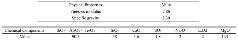
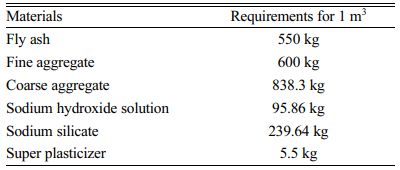
Geopolymer concrete was made with Class F fly ash with a low calcium concentration. Table 1 lists the characteristics of fly ash.
Aggregate
The crushed angular stone aggregate provided by the local quarry and the nearby available, well-graded natural river sand were used, both of which met the IS 383-1970 and IS 2386-1963 (I, II, and III) standards [16].
Sodium Hydroxide
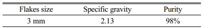
The sodium hydroxide used was solid-state sodium hydroxide in the form of 3 mm flakes with a purity of 98 percent [17]. The value of sodium hydroxide is determined by its purity. The characteristics of sodium hydroxide are listed in Table 2.
Sodium Silicate Solution
For Geopolymer concrete, a sodium silicate solution with a mass ratio of SiO2 to Na2O is recommended. The characteristics of sodium hydroxide are exhibited in Table 3.
Super Plasticizer
CONPLAST–SP 430 was used to increase the workability of concrete and complies with IS 9103-1999 in the form of sulphonated Naphthalene polymers.
Alkaline Liquid
Sodium hydroxide pellets at 8 molar concentrations were dissolved in water. The sodium hydroxide solution and sodium silicate gel must be mixed and made at least 24 hours ahead of time, and the produced solution must be utilized within 36 hours otherwise it will solidify [18, 19]. Since sodium silicate solution is far less expensive than sodium hydroxide solution, the mass ratio of sodium silicate solution to sodium hydroxide solution was set at 2.5 for the majority of the mixes.
Sisal Fiber
Sisal is a pure biodegradable organic natural fiber substance that contains 46% lignin and 54% cellulose [20]. Sisal is strong, tough, and polygonal in section, with a high tearing strength, owing to its high lignin concentration. The diameter of the sisal fiber was 0.75 mm, with an aspect ratio of 80. The characteristics of sisal fiber are displayed in Table 4.
Material Proportions
A concrete grade of M30 was created. Trial and error were used to create geopolymer concrete. The material requirements for 1m3 of M30 Geopolymer Concrete are listed in Table 5.
Fiber Proportion
Based on compressive, tensile, and flexural test findings, sisal fibers with concentrations of 0.2 percent, 0.4 percentage, 0.6 percentage, 0.8 percentage, and 1 percentage by volume are used in specimens to determine the appropriate fiber dosage.
Casting and Curing Of Specimens
The strength-related properties of geopolymer concrete with fibers were studied by experimental research on the specimen. 150 × 150 × 150 mm, 150 mm × 300 mm, and 100 mm × 100 mm × 500 mm are the specimen sizes for the cube, cylinder, and prism, respectively. Steam curing was done for 24 hours at 60 °C. For each mix, a minimum of three specimens were cast.
Strength-Related Properties
By the duration of 28 days, experimental tests were carried out on hardened conventional concrete and geopolymer concrete with and without various percentages of sisal fibers to assess the strength-related properties. Based on the results of the tests, the optimum percent addition of sisal fiber was found [21, 22].
Strength Tests
The flexure strength test, also known as the modulus of rupture test, was performed on concrete beams measuring 100 mm × 100 mm × 500 mm with a span three times their depth in line with IS: 516-1959 codal criteria.
Behaviour Of Geopolymer Rcc Beams
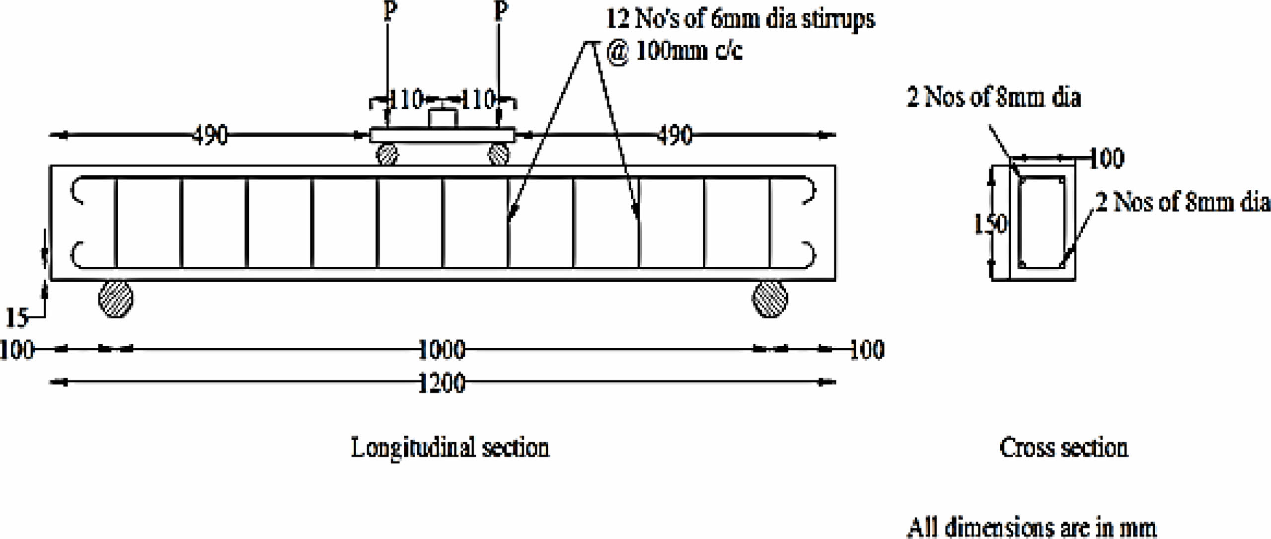
Reinforced geopolymer concrete beams are being tested in this experiment. The cross-section of the beam was 1200 × 150 × 100 mm [23]. RCC beams with and without the addition of 0.6 percent sisal fiber was cast for conventional concrete and geopolymer concrete. A beam is a structural component that supports all vertical loads and prevents bending. Beams can be made out of a variety of materials, including steel, wood, aluminum, etc. However, reinforced cement concrete is the most often utilised substance (RCC). Figure 1 depicts the beam specs.
Size of the beam = 1200 mm × 150 mm (Depth) × 100 mm (Breadth)
Cover = 15mm
Ast = 4 Nos. of 8 mm dia bars = 201.06 mm2
Stirrups = 6 mm dia rods @ 100 mm c/c
Clear distance = 1000 mm
Effective depth = 131 mm
Determination Of Ultimate Load Of RCC Beams
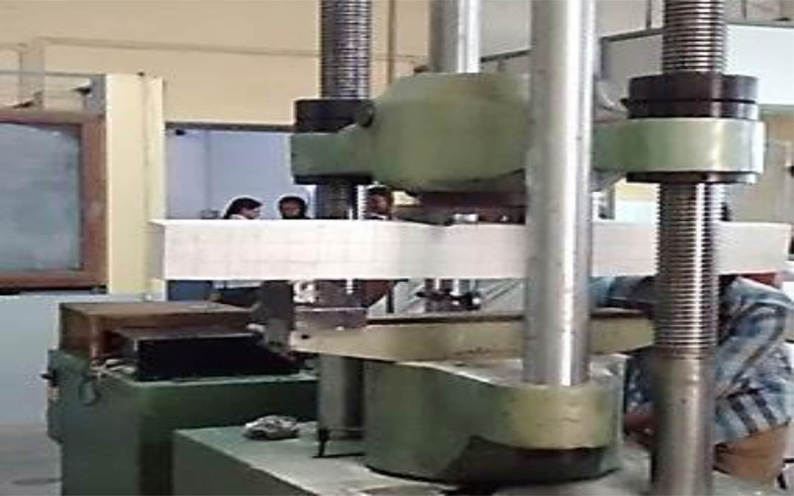
Two-point loads were applied to the beam to determine its ultimate load. The load-deflection test is depicted in Fig. 2.
Determination Of Load-Deflection Behavior
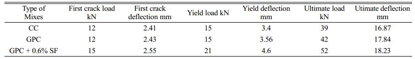
Load-deflection experiments were carried out. The fracture load, yield load, and ultimate load, as well as their associated deflections, were discovered.
Determination Of Energy Absorption Capacity
Energy-absorbing capability of the RCC beam was determined using load-deflection curves that were sketched.
Energy absorption capacity = Sum of the area below the load-deflection curve up to the ultimate load point
Determination of Toughness Indices
The indices have a minimum value of one for elastic-brittle behavior and a maximum value of five, ten, or thirty for optimum elastic-plastic behavior, accordingly.
Determination of Ductility Factor
When f stands for the displacement at failure and y for the yield displacement, the ductility factor is defined as f/y. The aspect ratio between the height and length of the frame panel, the ratio between the inertia of the beam and the inertia of the column, and the configuration of connecting details are the main factors in the study.
The yield load point and ultimate load point induced deflections, which were recorded.
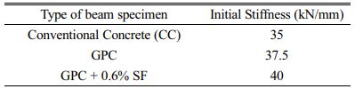
Determination of Initial Stiffness
The flexural strength divided by the yield curvature of the wall is thought to be a suitable starting stiffness definition for a straightforward structure, like a cantilever wall. This ratio is equal to the product of the second moment of inertia for the fractured section and the elastic modulus.
With regard to the load-deflection curves, the first tangent was drawn.
Initial stiffness = Slope of the first tangent of the load-deflection curve
|
Fig. 1 Specification of RCC Beam |
|
Fig. 2 Load-deflection tests in progress. |


General
The strength properties of M30-grade conventional concrete, geopolymer concrete, and fiber-reinforced geopolymer concrete were discovered and summarised. CC and GPC indicate conventional concrete and geopolymer concrete specimens, respectively. GPC-1, GPC-2, GPC-3, GPC-4, and GPC-5 refer to the addition of sisal fibre in various percentages of 0.2 percentage, 0.4 percentage, 0.6 percentage, 0.8 percentage, and 1 percentage by volume.
Experimental Results
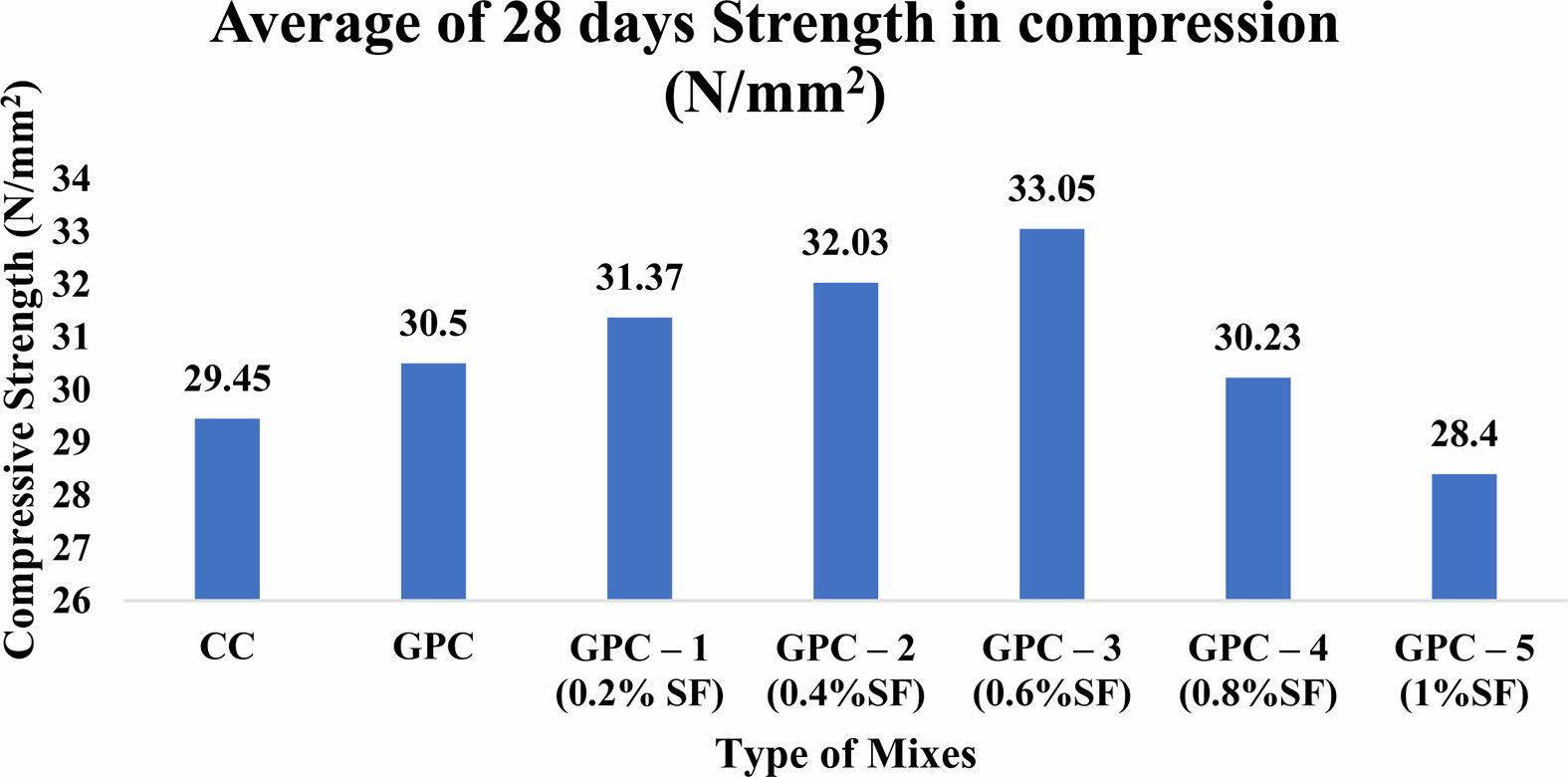
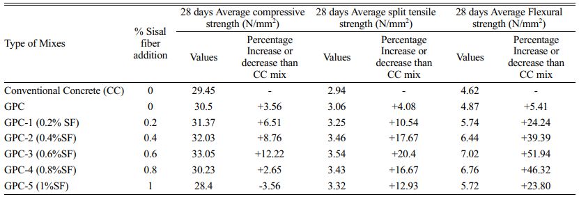
Results of Compressive strength test, Spilt Tensile Strength test and Flexural Strength test : The peak load achieved by crushing the specimen was used to calculate the compressive strength. The compressive strength spilled tensile strength, and flexural strength values of conventional concrete (CC), geopolymer concrete (GPC), and various % additions of sisal fiber in geopolymer concrete are shown in Table 6. (GPC-1 to GPC-5).
Table 6 and Fig. 3 show that a 0.6 percent addition of sisal fiber results in maximum compressive strength (33.05 N/mm2) at 28 days, which is 12 percent higher than standard concrete. According to the test results, increasing the proportion of sisal fiber up to 0.6 percent increment in compressive strength, then more than that, compressive strength steadily falls.
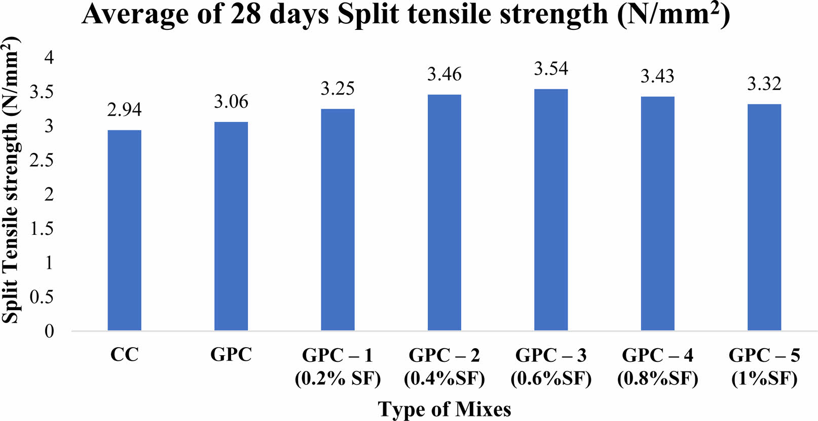
Table 6 and Fig. 4 show that at the age of 28 days, a 0.6 percent addition of sisal fibre produces maximum split tensile strength (3.54 N/mm2), which is 20 percent higher than standard concrete. According to the test results, increasing the proportion of sisal fibre up to 0.6 percent increases split tensile strength, but beyond that, the split tensile strength steadily declines.
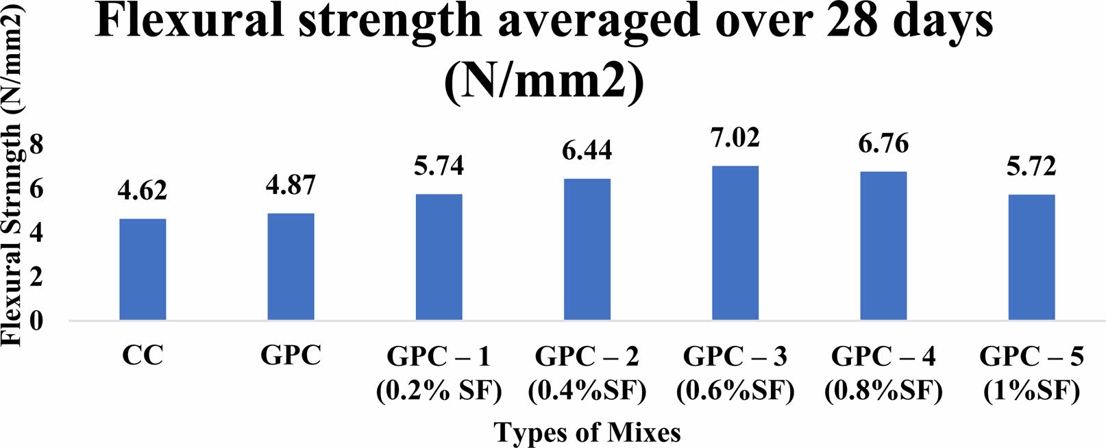
Table 6 and Fig. 5 show that at 28 days, a 0.6 percent addition of sisal fiber results in maximum flexural strength (7.02 N/mm2), which is 51 percent higher than standard concrete. According to the test results, increasing the proportion of Sisal fiber up to 0.6 percent increases flexural strength, but beyond that, the flexural strength steadily diminishes.
Test on RCC beam
Based on the findings of the strength tests, 0.6 percent sisal fibers were added to the Geopolymer concrete. The beam with dimensions of 1200 × 100 × 150 mm was cast and tested utilizing two points of loading for the flexural behavioral research. The strain gauge was used to measure the deflections, which had a minimum count of 0.01 mm. Table 7 illustrates the test results for a standard M30 grade concrete RC beam, a GPC beam, and a GPC beam with 0.6 percent sisal fiber added. It was determined the ultimate load, energy absorption, toughness index, ductility factor, and initial stiffness.
Modes of failure in RCC beam
In the flexural zone, all reinforced concrete beams failed. The reinforcement began to yield after the first crack load, and an increasing number of cracks occurred in the flexural zone, extending towards the point loads as the loads increased. The flexural zone of the standard concrete sample has a higher number of cracks. The number of cracks in the flexural zone is lower in specimens with fiber content. It implies that the fiber contributes to the beam's strength and stiffness.
Load Deflection relationship
M30 conventional, geopolymer, and geopolymer concrete specimens with a proportional of 0.6 percent Sisal fiber underwent a load and deflection test.
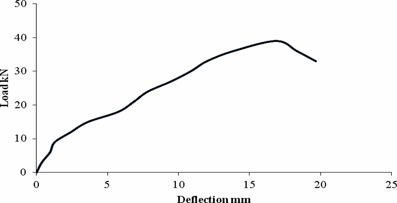
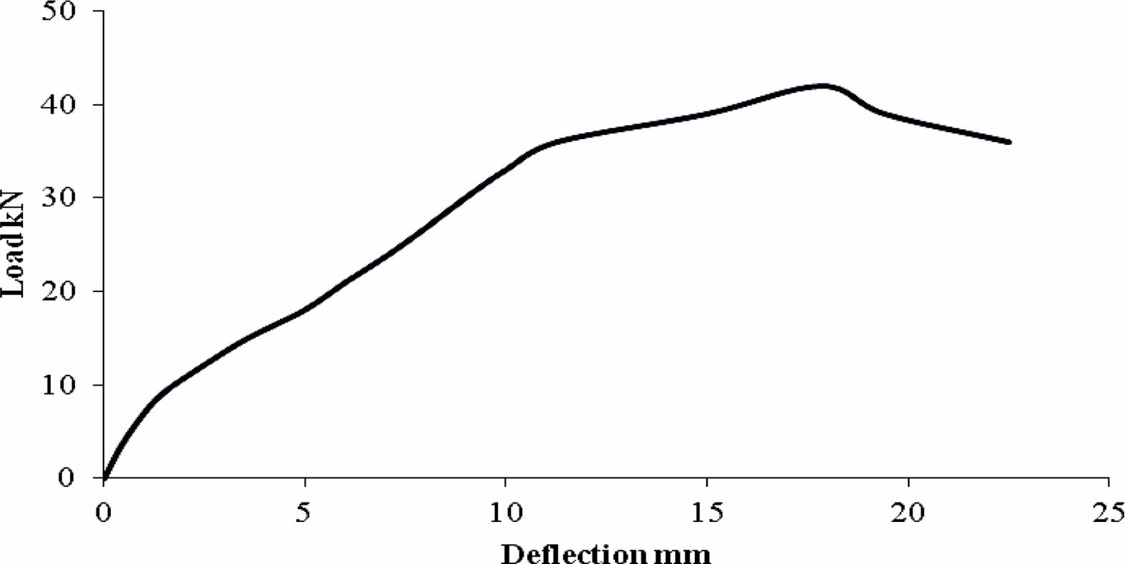
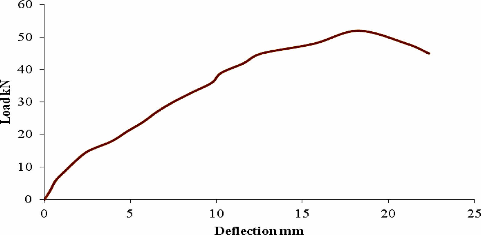
Figures 6, 7, and 8 depict load-deflection relationships for conventional and geopolymer RCC beams with fibers spread over the entire depth. In general, fiber volume percentage does not affect the load-deflection relationship; however, all beam specimens containing sisal have a stiffer response during the post-cracking stage. Fibers operate as crack bridging in Geopolymer concrete, allowing it to withstand loads even after cracks appear in the concrete.
Determination of Energy absorption capacity
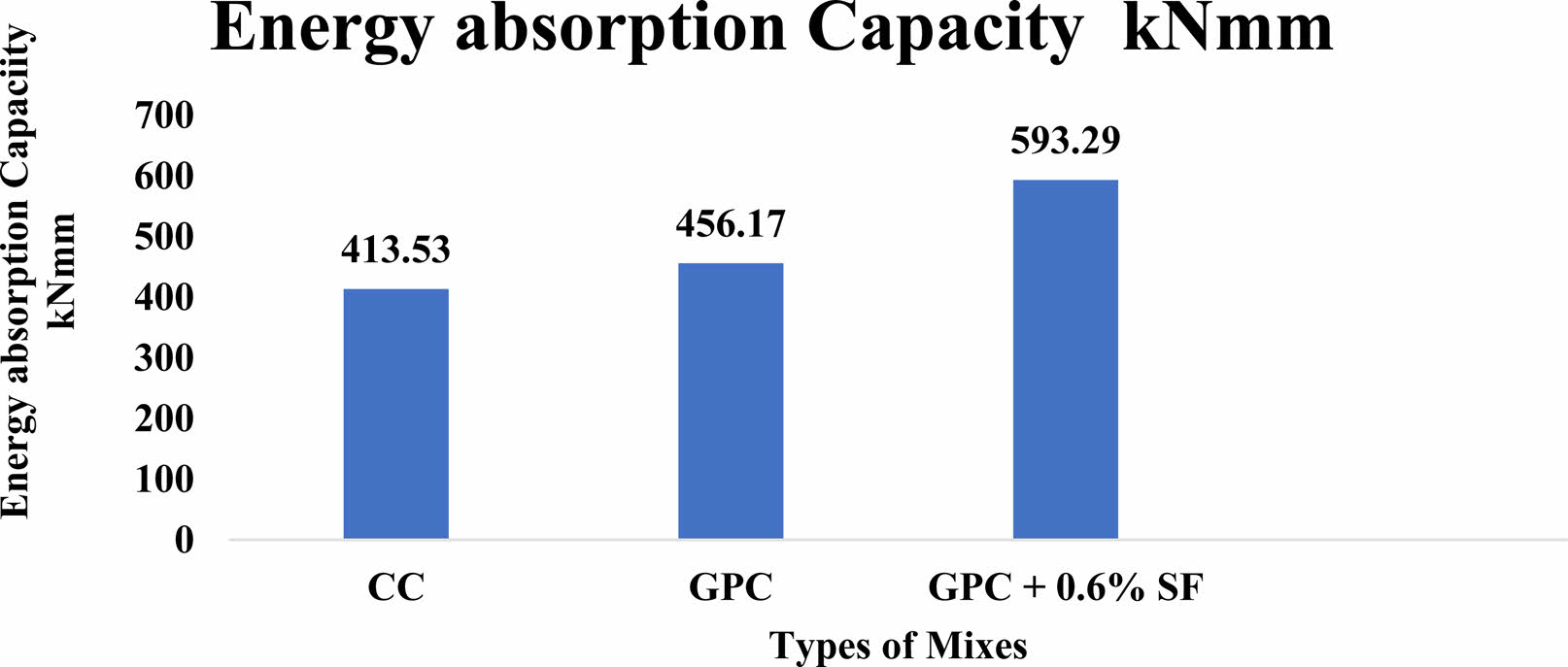
A building material made by mixing cement, sand, aggregates, and water in the proper proportions, then curing the plastic mixture to form a hard mass, is known as cement concrete. It is simple to mold into sturdy building parts. Aggregate content in concrete ranges from 60 to 78%. The load-deflection test revealed the RCC beam's energy absorption capacity. The energy capacity estimates of RCC beams are shown in Fig. 9. The energy absorption capability of Geopolymer concrete containing 0.6 percent sisal fiber is higher than that of conventional and geopolymer concrete.
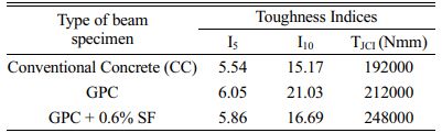
Table 8 shows the toughness indices for all of the specimens. The Toughness Indices of Geopolymer concrete with 0.6 percent Sisal fiber are higher than those of conventional and geopolymer concrete.
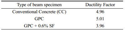
The Ductile Factor of 0.6 percent Sisal fiber mixed Geopolymer Concrete is less than that of conventional and geopolymer concrete, according to Table 9.
Table 10 reveals that the Initial Toughness Indices of Geopolymer concrete with 0.6 percent Sisal fiber are greater than those of conventional and geopolymer concrete.
In comparison to conventional and geopolymer concrete, geopolymer concrete with 0.6% sisal fiber has a better energy absorption capacity. The hardness indices for each specimen are displayed in Table 9. In comparison to conventional and geopolymer concrete, geopolymer concrete with 0.6% sisal fiber has greater toughness indices. Table 10 shows that the Ductile Factor of geopolymer concrete containing 0.6% sisal fiber is lower than that of geopolymer and ordinary concrete. The Initial Toughness Indices of the geopolymer concrete with 0.6% sisal fiber are higher than those of the geopolymer and conventional concrete, as shown in Table 10.
The geopolymer concrete has restrictions regarding the delay in setting time. Sisal fiber inclusion is advised to achieve improved strength at an early stage. c. The 0.6% volume fraction of sisal fibers added increased the compressive, tensile, and flexural strengths by 12%, 20%, and 50%, respectively, in comparison to the CC. In compared to the GPC, the compressive, tensile, and flexural strengths rose by 8%, 15%, and 44%, respectively, with the addition of sisal fibres at a volume fraction of 0.6% during heat curing. With the addition of polypropylene fibres at a volume fraction of 0.4%, the compressive and tensile strengths were enhanced by 16% and 26%, respectively, when compared to the CC. In comparison to the GPC, the compressive and tensile strengths rose by 12% and 21%, respectively, with the addition of polypropylene fibres in a volume fraction of 0.4% during heat curing. At 0.6% addition of polypropylene fiber, the improvement in flexural strength is at a rate of 59% and 51%, respectively, when compared to CC and GPC, so it is regarded as optimal.
|
Fig. 3 Compressive strength of GPC with Sisal fiber. |
|
Fig. 4 Split Tensile strength of GPC with Sisal fiber. |
|
Fig. 5 Flexural strength of GPC with Sisal fiber |
|
Fig. 6 Load vs. Deflection curve for M30 grade Conventional Concrete. |
|
Fig. 7 Load vs. Deflection curve for M30 grade Geopolymer Concrete. |
|
Fig. 8 Load vs. Deflection curve for M30 grade Geopolymer Concrete with Sisal Fiber. |
|
Fig. 9 Energy Capacities of Specimens. |
|
Table 6 Compressive strength, split tensile strength, and flexural strength values. |
Based on the experimental findings, the following conclusions are drawn: When 0.6 percent sisal fiber is added to Geopolymer concrete, it results in stronger strength and durability than standard concrete. The increased area of bonding in the interface region of the matrix and fiber increases the flexural strength of geopolymer concrete containing fibers. Because additional voids emerge in the concrete and the materials are not properly bonded beyond the optimum, the strength is lowered. In experimental RCC beams, fiber inclusion improves ultimate load-carrying capacity, reduces stiffness degradation, and raises ductility factor by 0.6%. The ASTM C1018 and JCI protocols were used to achieve the Toughness Index values. All of the beams have almost the same value. When fibers are added, the energy absorption capacity significantly rises by 0.6%. Fiber with an improved toughness of 0.6% can be used to regulate shrinkage and cracking temperature. Environmentally friendly concrete with the necessary strength can be produced by combining waste materials like fly ash with fibers. This lowers air pollution and greenhouse gas emissions. The investigation of GPC beams with fiber can be included to the future work.
- 1. G.E. Arunkumar, P. Chandrasekaran and T. Senthilvadivel, Pol. J. Environ. Studies 30[2] (2021) 1129-1137.
-

- 2. K. Athiappan and S. Vijaychandrakanth, Int. J. Eng. Res. Technol. 3[5] (2014) 1500-1505.
- 3. G.D. Kumar, T.D. Raj, P. Chandrasekaran and S.K. Maniarasan, Int. J. Scient. Res. Develop. 5[1] (2017) 1116-1118.
- 4. S. Velusamy, A. Subbaiyan, S.R. Murugesan, M. Shanmugamoorthy, V. Sivakumar, Adv. Mater. Sci. Eng. (2012).
-
- 5. N. Ganesan, R. Abraham and S.D Raj, Construct. Build. Mater. 93 (2015) 471-476.
-
- 6. S.K. Maniarasan, V.S. Kumar, P. Chandrasekaran, Int. J. Scient. Technol. Res. 9[2] (2020) 1631-1639.
- 7. S. Vajje and N.R. Krishnamurthy, Int. J. Scient. Technol. Res. 2[11] (2013) 213-218.
- 8. A.R. Krishnaraja, P. Kulanthaivel, P. Ramshankar, V.H. Wilson, P. Palanisamy, Adv. Mater. Sci. Eng. (2022).
-
- 9. S.R. Murugesan, V. Sivakumar, S. Velusamy, G. Ravindiran, P. Sundararaj, Adv. Mater. Sci. Eng. 2022 (2022) 00-07.
-
- 10. D. Satheesh, S.K. Maniarasan and P. Chandrasekaran, Int. J. Adv. Sci. Eng. Res. 3[1] 63-69.
- 11. S.H. Sanni and R.B. Khadiranaikar, Int. J. Res. Eng. Technol. IC-RICE Conference Issue (2013) 366-371.
- 12. M.S. Shetty, in “Concrete Technology,” (S. Chand and Company Pvt Ltd, 2012).
- 13. S.S. Bidwe and A.A. Hamme, American J. Eng. Res. 4[3] (2015) 139-145.
- 14. S.S. Ilamvazhuthi and G.V.T. Gopalakrishna, Int. J. Innovat. Eng. Technol. 3[2] (2013) 148-155.
- 15. R. Prabhu, R. Anuradha and S. Vivek, Asian J. Eng. Appl. Technol. 5[2] (2016) 15-21.
- 16. S. Vivek, K. Janani, M. Divyadharsini, C.M. Dharmalingam, S. Srinivasan, Int. J. Chem. Tech. Res. 10[8] (2017) 739-749.
- 17. T. Sen and H.N. Jagannatha Reddy, Int. J. Innovat. Manag. Technol. 2[3] (2011) 186-191.
- 18. K. Uma, R. Anuradha and R. Venkatasubramani, Int. J. Civil Struct. Eng. 2[3] (2012) 817-827.
- 19. J. Won and S. Kang, J. Ceram. Process. Res. 18[2] (2017) 166-171.
- 20. Y. Kim, S. Kim and T. Chae, J. Ceram. Process. Res. 18[3] (2017) 214-219.
- 21. S. Kavipriya, C. G. Deepanraj, S. Dinesh, N. Prakhash, N. Lingeshwaran, Materials Today 47[15] (2021) 5503-5507.
-
- 22. G. Zila, D. Oliveira, J. Filho and N. Silva, J. Build. Eng. 43(2021) 102568.
-
- 23. A.N. Arasu, S. Vivek, J. Robinson and T.T. Ranjith, Int. J. Chem. Tech. Res. Coden. 10[8] (2017) 605-622.
 This Article
-
2022; 23(6): 912-918
Published on Dec 31, 2022
- 10.36410/jcpr.2022.23.6.912
- Received on Jul 25, 2022
- Revised on Sep 13, 2022
- Accepted on Sep 14, 2022
Services
Shared
Correspondence to
- Muthupandy Varuthaiya
-
Department of Civil Engineering, Hindusthan College of Engineering & Technology, Coimbatore, Tamilnadu, India - 641032
Tel : + 919566951005 - E-mail: muthupandyvaruthaiya@gmail.com
Clean-Energy Research Institute(CRI), Hanyang University, 222, Wangsimni-ro, Seongdong-gu, Seoul, 04763, Korea
E-mail: jcpr@hanyang.ac.kr