


- Machining performance and optimization of inconel 718 using MWCNT by taguchi’s method
Sriharrish Kumara,*, Sureshkannan Gurusamyb, Vivek Sivakumarc and Senthil Murugan Vaiyapurid
aDepartment of Mechanical Engineering, Hindusthan College of Engineering and Technology, Coimbatore, Tamilnadu
bDepartment of Mechanical Engineering, Coimbatore Institute of Technology, Coimbatore, Tamilnadu
cDepartment of Civil Engineering, Hindusthan college of Engineering and Technology, Coimbatore, Tamilnadu
dDepartment of Mechanical Engineering, Hindusthan college of Engineering and Technology, Coimbatore, TamilnaduThis article is an open access article distributed under the terms of the Creative Commons Attribution Non-Commercial License (http://creativecommons.org/licenses/by-nc/4.0) which permits unrestricted non-commercial use, distribution, and reproduction in any medium, provided the original work is properly cited.
Inconel718 has distinctive qualities, including excellent oxidation resistance, corrosion resistance even at very high temperatures, and retention of a high mechanical strength under these conditions, Inconel 718 has found its niche in numerous industries. As a result, it is frequently utilized in harsh environments, including marine applications, pressure vessels, steam turbine power plants; aircraft engine parts, chemical processes, and pressure vessels. Due to its special qualities that are needed for engineering applications, the superalloy Inconel 718 is frequently utilized in complex applications. Superalloy Inconel 718 is challenging to machine and expensive because of its unusual properties. With the use of a tungsten carbide cutting tool, Inconel 718 is being turned at a fast speed in this work in an effort to apply Taguchi optimization approach to optimise cutting parameters. Inconel 718 is thought to have a relatively poor machinability. Regardless, this composite is hard for machining, considering high hardness. The proposed system is to pick the impact of controllable parameters on machining credits of Inconel718 and to accomplish the ideal parameters for reasonable and effective turning. Nanofluid is normally used to diminish the temperature during machining and to improve machining parameters. This examination is to inspect the effect of dispersed Multi walled Carbon Nanotube (MWCNT) and engine oil nanoparticles on overhauling the cooling and oil capacities during the turning of Inconel718. The turning parameters of Inconel718 are advanced by utilizing Taguchi's structure. Turning assignments were done with PVD TiAlN guaranteed about the carbide cutting instrument presents. Three organized cutting rates, feed rates, and essentialness of cut were used by turning tests. Improved cutting parameters are utilizing the assessment of progress. The influence of machining parameters such as cutting speed and feed rate on surface abhorrence, cutting power, and contraption wear was investigated. Cutting parameters such as cutting rate, feed rate, and cut centrality were chosen at various levels for experimentation in the Taguchi L9 pack technique. Cutting rate and feed rate on surface reality, cutting power, and mechanical social event wear was devastated. The outcomes uncovered that the feed rate is influencing the surface viciousness and cutting power. The cutting pace was viewed as influencing contraption wear. The test study is done on the following surface malice, material clearing rate, and instrument wear rate. The insistence tests are done at faultless cutting conditions. The outcomes got from the total of the levels were all close; with everything considered, the upgraded parameters are procured for fit machining of Inconel718
Keywords: Surface roughness, Depth of cut, Cutting velocity, Feed, Tool wear, MWCNT, MRR, Taguchi method
Dry machining produces a high temperature and significant adhesive wear in between tool and the work piece, Inconel718 is a nickel-based super alloy that is difficult to turn due to its hardness of 40HRC [1]. Due to the high temperature and robust adhesive wear in between tool and the work material, conventional cutting tools typically have quick wear rates. During machining processes, a lot of heat is produced along with an increase in surface roughness and the rate of tool wear [2]. High residual stresses are the main cause of the failure of these material components. But super alloy is suitable for aerospace industries to make precision aircraft elements. To address these issues, several studies have been conducted using more expensive tools such as coated carbide (PVD (Ti, Al) N–TiN and CVD Ti (C, N)–Al2O3–coated tools, etc.), ceramic and (P) CBN in dry machining and hard cutting under base oil nanofluids. But this Cutting fluid applies at high pressure in the chip forming zone. It affects the environment and creates the problem of disposal of cutting fluid [3].
The term "nanofluid" refers to a liquid that contains nanometer-sized particles. The thermal conductivity of nanofluids is improved with a low volume division (0.1 percent) of suspended particles. Nanofluids can be used to cool car motors and welding equipment, as well as high-heat-transfer devices like microwave chambers and high-power laser diode packs. Multi-walled carbon nanotubes (MWCNTs) are stand-out kinds of carbon nanotubes where unmistakable single-walled carbon nanotubes are settled inside each other [4]. In MWCNT blended in with the oil, the nanoparticles are among the nano-included substances that have dominating properties [5]. The estimations of these nano-included substances move from a couple of nano meters to various nano meters and CNTs length loosens up between various nano meters to two or three centimeters. During machining, a nanofluid is used to lower the starting cutting temperature in shear zones and to provide oil to reduce concentration on the instrument workpiece interface zone [6].
MWCNT with motor oil is having regular properties including incredible warm conductivity, high gauge, and faithfulness. These properties empower the resultant nano-liquid to withstand the high-made temperature during machining [7]. Nano-included substances type is commonly identified with their unavoidable cooling and oil characteristics which would improve the resultant nano-liquid and warmth move properties. This methodology is a space inviting option rather than the standard flood coolant with constructed oils. The tests are evaluations that wire power ate up during the cutting framework, surface mercilessness, instrument wear, and material expulsion rate [8].
The use of PVD-coated Titanium carbide insert tools in hard turning with nanofluids is not discussed in any of the previous articles. Amidst the machining endeavors, slicing liquids are identified as the root of the quality and contraption wear and restored machining parameters. After constrained time length days, nanofluids have in a like way shown up. Exploratory results are improved by Taguchi's structure [9]. The surface quality and contraption wear rate are improved with our proposed structures and super mix machining settings (cutting speed, feed rate, and noteworthiness of cut). Titanium with PVD made sure about carbide embeds tool shows finishing the way toward planning attempts in the CNC machine. Existing structures used straight oils with a blend of nanofluids and nanotube. Here we use the MWCNT and motor oil of nanoparticles with high-pressure flooding [10].
Workpiece material
Superalloys are a social gathering of nickel, iron-nickel, and cobalt mixes. These metals have stunning warmth-safe properties and hold their consistent quality, quality, sturdiness, and dimensional steadfastness at temperatures in a general sense higher than the distinctive air transportation accomplice materials [11]. Inconel 718 is a nickel-chromium amalgam known and used for disintegration and sublime utilization deterrent, high bore, and raised temperatures. Considering its insurance from disintegrating, weight, and warmth, amalgam 718 is ideal for applications in Aircraft ducting structures, flight, fabricated methodology gear, and nuclear and marine endeavors [12]. Inconel types like Inconel 600, Inconel 625, Inconel 718, Inconel 800, and Among the items made of Inconel 825 are pipes, sheets, plates, bars, spines, fittings, tubes and locks. The yield, flexibility, and creep-splitting qualities of this nickel steel combination are similarly astoundingly impressive at high temperatures. Convexity at greater temperatures, hardness, and destructive qualities are sufficient at higher temperatures as steel, which is the normal astounding condition of inconel718, as opposed to solidified steel [13, 14].
The turning tests are conducted by a heavy-duty LMW Turn master-LX 20TL3 CNC lathe with a variable speed range of 500 to 3000 rpm and a 7.5 kW power rating.
Table 1 shows the Chemical Compositions of Inconel718. Table 2 shows the Mechanical Properties of Inconel718. Table 3 shows the Cutting Parameters and their Levels.
Cutting tool
An ensured Carbide contraption with a hard layer of PVD TiAlN is utilized to end dealing with the endeavors of Inconel718. As showed up by the pre-owned cutting instrument material, workpiece material, and machining structure, the 13 fixings to be utilized in a covering are settled to develop the execution of the cutting contraption. Standard hard covering properties that ought to be satisfied at the bleeding edge under working conditions (high weight and temperature) [15]. Stunning hold quick to the substrate, and between the layers by the sensibility of multi-layer (remarkable relationship with the substrate is a central condition for appealing execution of the affirmed contraptions). High hardness at working temperature (hot hardness) of the instrument (hard coatings add to broadened beating wear catch). Choice (covering break quality is as focal as hardness). Coatings are kept by three sorts of the system which make out of vaporous state, plan state, liquid, or semi-fluid state structures. Two manager trademark parameters for the covering structures are the thickness of the coatings that can be entered (from 0.1 mm to 10 mm) and the referenced temperature (from room temperature up to 1000 °C). Two head accreditation structures utilized in the use of hard coatings on cutting mechanical shows are PVD [16].
Nanofluids
Nanofluids are nanoparticle suspensions in fluids with dramatically improved characteristics at nanoparticle centers. Nanofluid as a sharp fluid, where warmth move can be reduced or improved uninhibitedly, has furthermore been represented.
Preparation of MWCNT with engine oil
Under the imposed load, these nanotubes may readily align and form this layer. It is generally known that lubricants containing carbon nanostructures can provide strong protective layers between sliding surfaces. In this instance, the produced layer still has CNTs in it, but with shorter lengths. MWCNTs are estimated to be 20-40 nm in size, 25 microns long, and 95% prudent. Ultrasonication producing MWCNTs is a widely used method to create short, open-completed carbon nanotubes, which have a length that is several times longer than their width.
The accompanying method for determining the condition of MWCNTs and nanofluids' engine oil:
(i) measure the mass of MWCNTs by a mechanized electronic mass balance with a precision of 0.1 m;
(ii) put MWCNTs into the checked engine oil and set up the MWCNTs and engine oil mix;
(iii) sonicate the mix reliably for 30 minutes with Cup horn sonicator to gain uniform dispersing of nanotubes in engine oil. Through this status, the temperature of nanofluids augments up to 55 ºC.
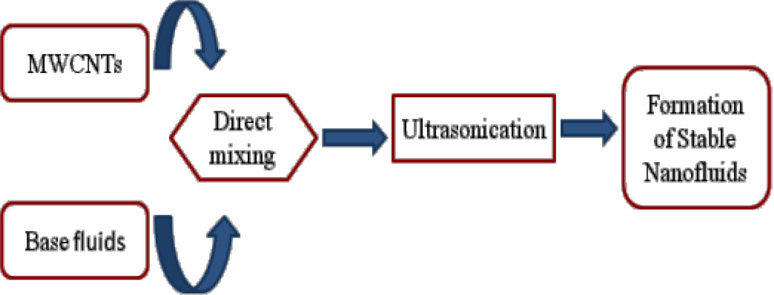
Figure 1 shows the preparation method for Nanofluid. The nanoparticles at room temperature by a sonication helped precipitation framework. The precipitation time was shifted during the game plan in order to better understand the effect of ultrasonic essentiality on atom size and path. A sonication time of 3 hours was viewed as perfect to make MWCNT nanoparticles with engine oil. A dynamic augmentation of the sonication time bit by bit lessens the atom size and extended surface zone.
Experimental details and analysis
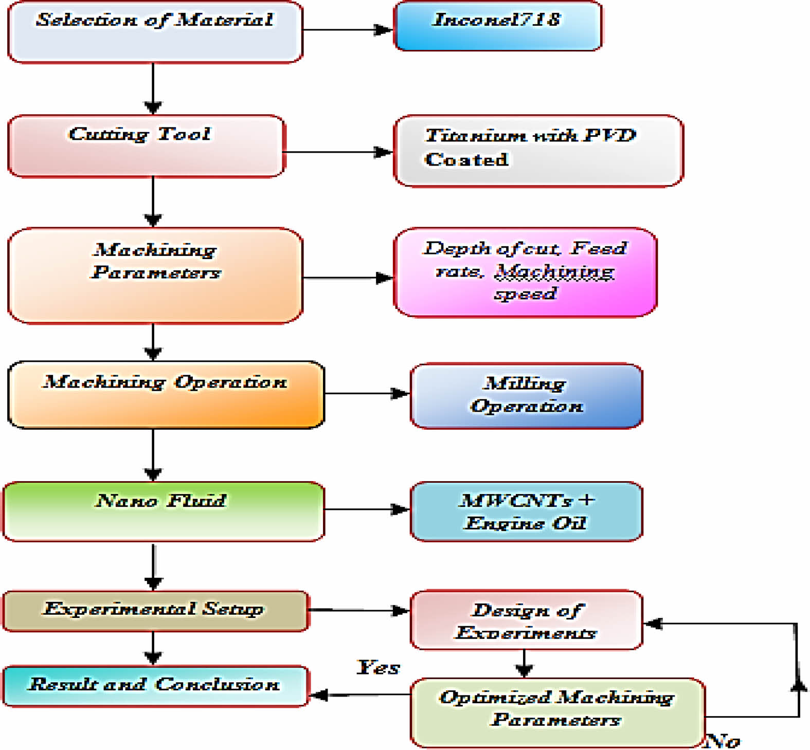
The examinations are organized using Taguchi's arrangement of investigation techniques. The investigation work is finished in Flow line Engineers, Chennai. The experimental data is inspected by using the sign to uproar extent (S/N extent) and the assessment of distinction (ANOVA). The S/N extent examination is used to find the perfect machining conditions. To determine the rate responsibility of the cutting speed and feed rate on surface harshness, cutting velocity, and tool wear rate, an ANOVA analysis is employed. Figure 2 shows the process of Machining.
Taguchi method
The suggested work for improving the machining of super alloys can be done to achieve a superior surface finish and which also influences the rate of material removal.
The Taguchi technique is a powerful design of experiments (DOE) tool for a engineering optimization. The improvement of measurement and the improvement of quality through the reduction of variability.
With the use of a tungsten carbide cutting tool, Inconel 718 is being turned at a fast speed in this work in an effort to apply Taguchi optimization approach to optimise cutting parameters. The Taguchi technique is a potent design of experiments (DOE) instrument for process engineering optimization. It is a crucial tool for determining each process parameter's ideal settings and for identifying the crucial parameters.
Taguchi's Method is a system/thing streamlining strategy that relies upon 8-steps of masterminding, coordinating, and surveying outcomes of network investigations to choose the best degrees of control factors. The basic goal is to keep the change in the yield low even inside seeing racket inputs.
The Taguchi plan streamlining system can be isolated into three stages:
(a) Structure plan
(b) Parameter structure and
(c) Obstruction plan.
Among the three stages, the parameter design sort-out is seen as a critical stage. The methods followed in the Taguchi parameter setup are: picking the most ideal balanced group (OA); running examinations subject to the OA; inspecting data; perceiving the perfect condition in addition, and driving confirmation run.
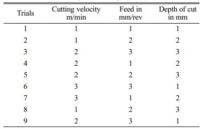
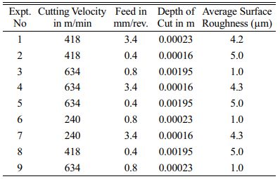
In this research work, interactions between factors are not considered. By referring above formulation; the L9 orthogonal array of Taguchi's is selected. Table 4 shows the values according to L9 orthogonal array.
|
Fig. 1 Preparation method for Nanofluid |
|
Fig. 2 Flow Process of Machining. |


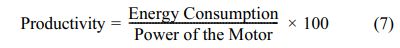
Effect on MWCNT with Engine oil Nanofluid
From the above-mentioned surface roughness graphs, it has been notified that when the depth of cut is in the range of 1.5-2.5 mm and surface roughness was found to be ranging from 1-5 µm as seen in (Fig. 3). The utilization of Nanofluid is to reduce the temperature and to improve surface roughness in the value of 1 µm.
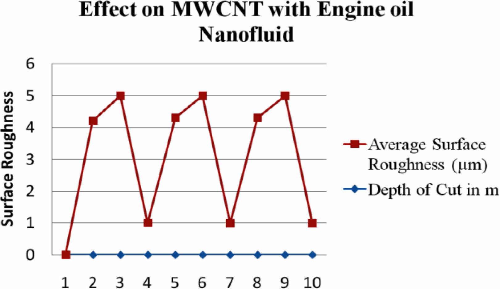
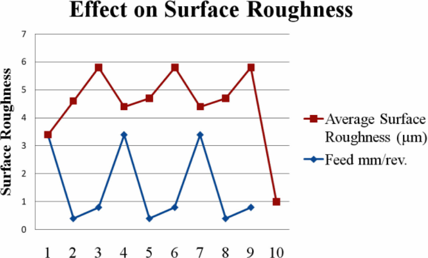
Effect on Surface Roughness (Ra)
The flow rate somewhere between 0.8-3.5 mm, or the cutting velocity somewhere between 200 and 700 m/min, according to the surface texture graphs previously provided and it was discovered that the surface roughness ranged from 1 to 5 m, as shown in Fig. 4 and Fig. 5. The cleaning impact comes considering irregularity in the size of sharp edges MWCNT nanoparticles help to clear kept burrs. Scouring the improvement of nanoparticles reduces workpiece material and MWCNT nanoparticle affiliation diminishes the difference thought of the machined surface.
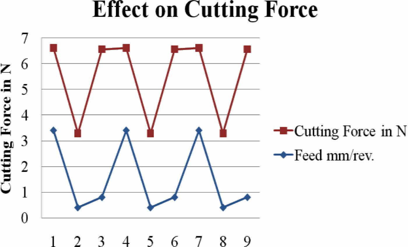
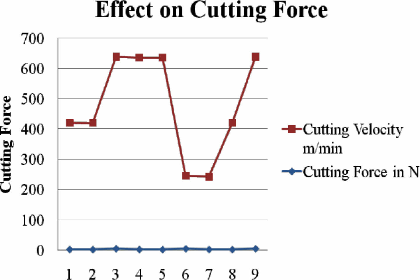
Effect on Cutting Forces
From the above-mentioned surface roughness graphs, it has been noted that when the feed rate is in the range of 0.8-3.5 mm, the cutting velocity is in the range of 200-700 m/min. and cutting force was found to be ranging from 2-6N as seen in Fig. 6 & Fig. 7.
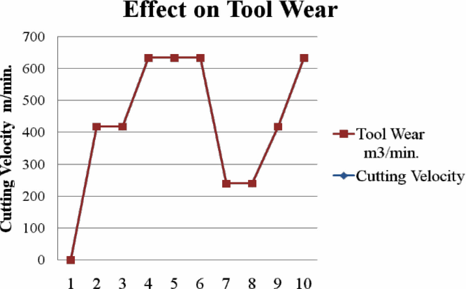
Effect on Tool Wear
From the above-mentioned tool wear graphs, it has been noted that when the cutting velocity is in the range of 200-700 m/min. and cutting force was found to be ranging from 2-6 N as seen in Fig. 8.
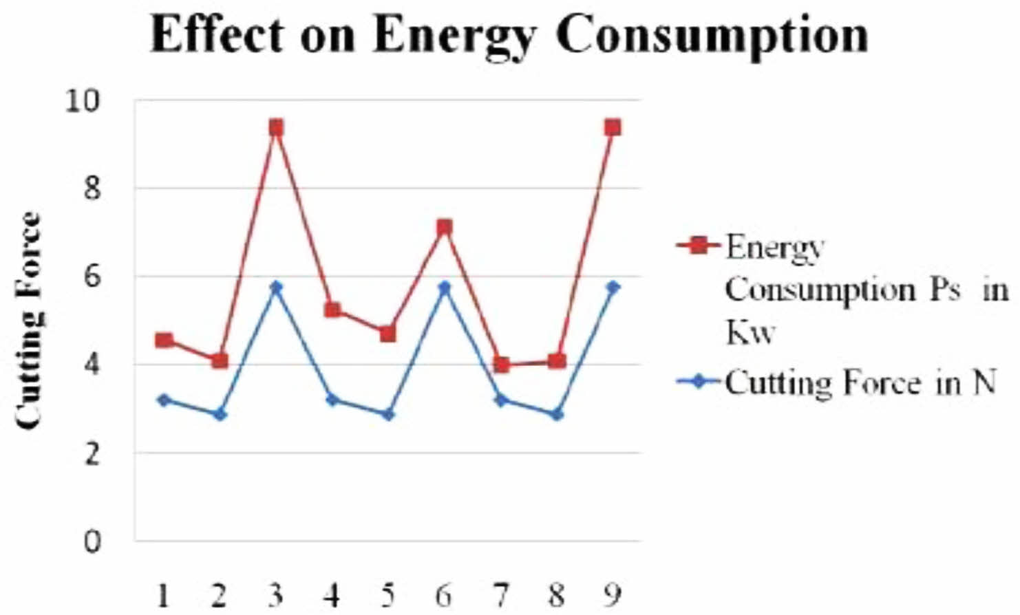
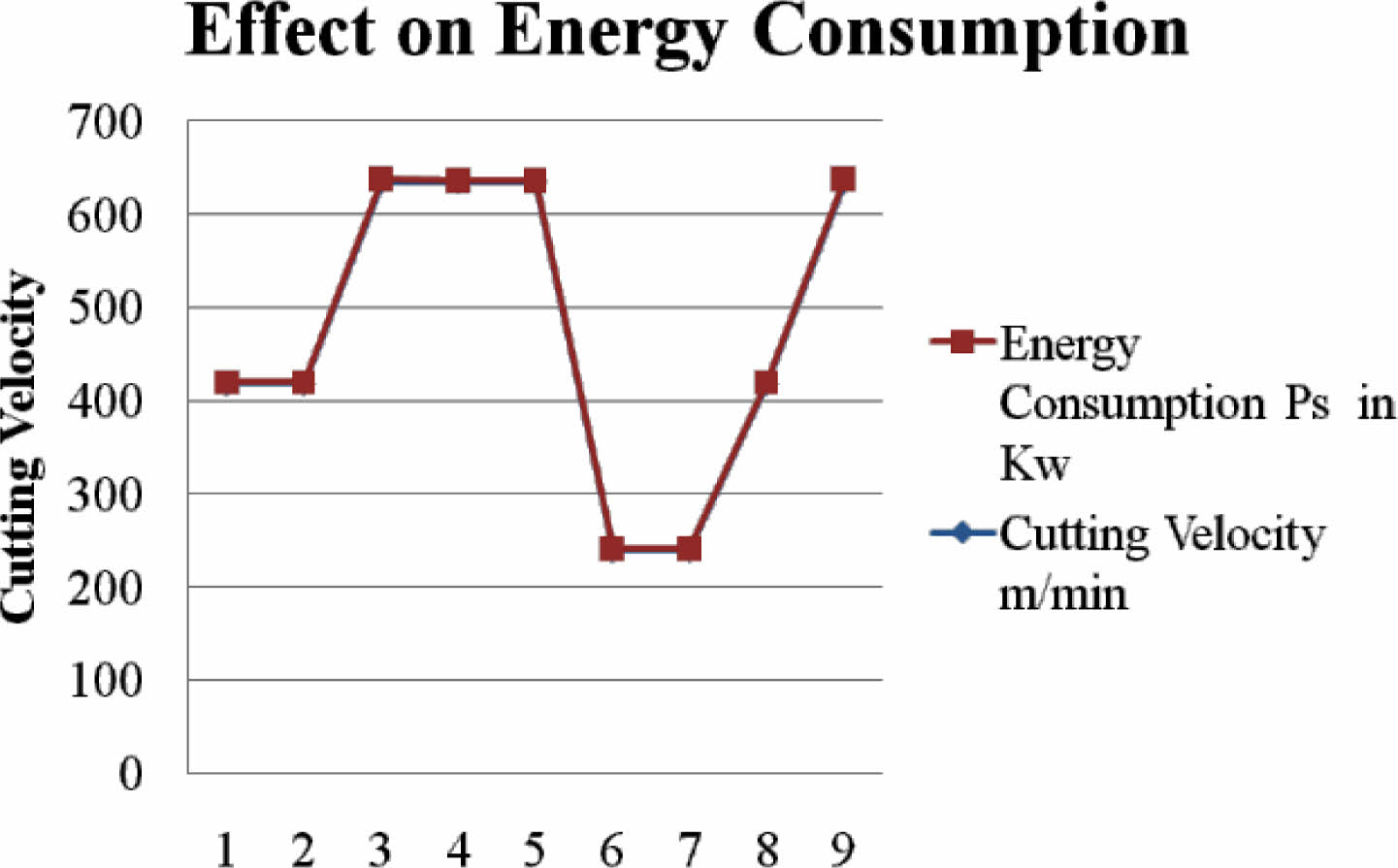
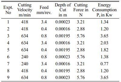
Effect on Energy Consumption
From the above-mentioned energy consumption graphs, it has been noted that when the cutting velocity is in the range of 200-700 m/min. and cutting force was found to be ranging from 2-6 N as seen in Fig. 9 & Fig. 10.
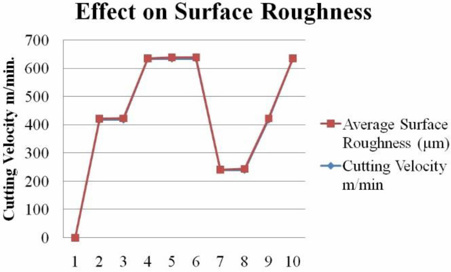
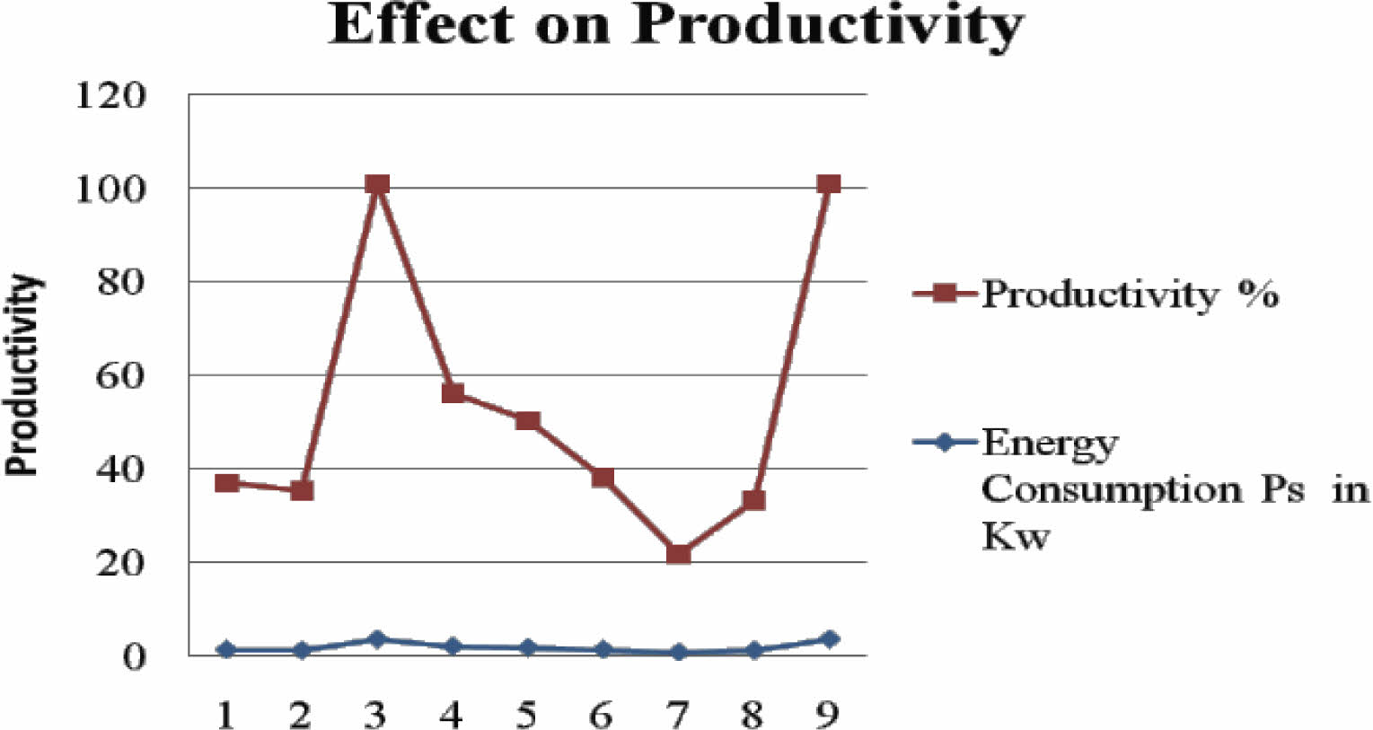
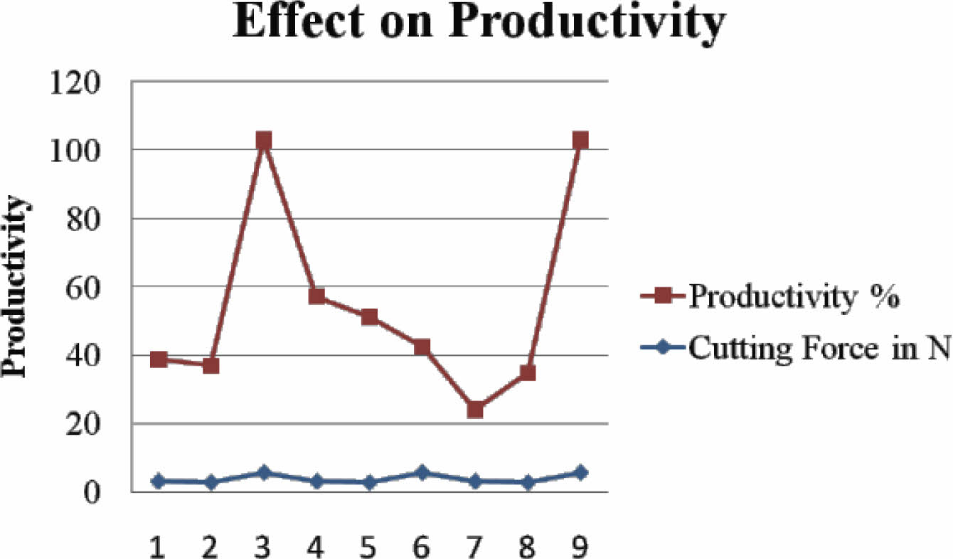
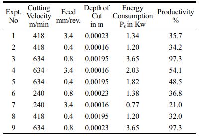
Effect on Productivity
From the above-mentioned productivity graphs, it has been noted that when the cutting force is in the range from 2-6N, energy consumption is in the range from 0.5 to 4 Kw, and productivity was found to be ranging from 20-98% as seen in Fig. 11 & Fig. 12.
Anova Results
The Experimental Results of Surface Roughness
The experimental results of Surface Roughness, Material Removal Rate (MRR) Cutting Force are depicted in Tables 5-7.
Surface Roughness

where,
r =Nose radius of tool, Average Surface Roughness Ra = hmax/4
Table 5 shows the experimental results for Surface Roughness (Ra).
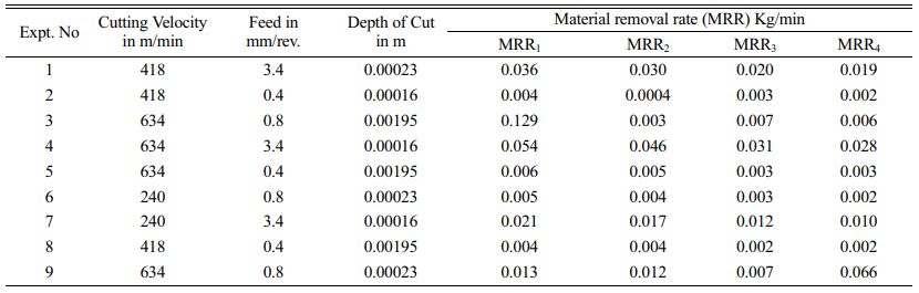
The experimental results of Material Removal Rate (MRR)

Where,
Vc = Cutting Velocity in m/min, f = feed in mm/rev and D = diameter of machining.
In Hinge Pin, having four different diameters for turning (Do, D1, D2, D3)
Where,
Do = 25.4 mm = 0.0254 m,
D1 = 20.14 mm = 0.0214 m,
D2 = 14.32 mm = 0.01432 m,
D3 = 13.00 mm = 0.013 mm.
Table 6 shows the experimental results for Material Removal Rate (MRR).
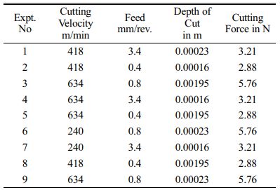
The Experimental Results of Cutting Force (Fc)

Tangential Cutting force Ft = Kc × (0.4 / f × Sinβ)Mc
Kc = 0.4: Specific cutting force at feed 0.4 mm/r
mc:Constant, depending on material. Use 0.29 as Inconel718 value. β = 1 and f = feed
Table 7 shows the experimental results for cutting force (Fc).
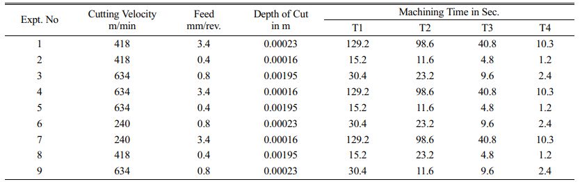
The Experimental Results of Machining Time
Length of Cut L1= 38 mm = 0.38 m
Length of Cut L2 = 29 mm = 0.29 m
Length of Cut L3 = 12 mm = 0.12 m
Length of Cut L4 = 3 mm = 0.38 m

Where,
f = feed and L = Length of Cut
Table 8 shows the experimental results for Machining Time.
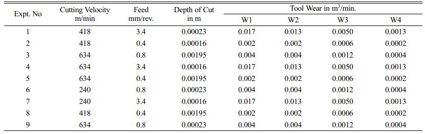
The Experimental Results of Tool Wear
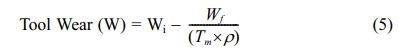
where,
Wi – Initial weight tool = 15.3 g,
Tm = Machining time
Wf – Final weight tool = 14.15 g,
ρ = Density of Inconel718 is 8800 g/m3
Table 9 shows the experimental results for tool wear.
The Experimental Results of Energy Consumption

Table 10 shows the experiment results for energy consumption.
The Experimental Results of Productivity
Where,
Power of the Motor = 3.75 Kw
Table 11 shows the experiment results for productivity.
The experimental Confirmation of Test Results
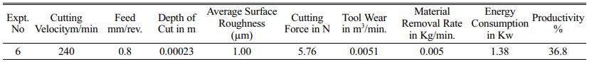
Table 12 shows the confirmation of Test Result.
The explanation behind this test was to examine the effect of MWCNT with Engine oil nanofluid on the evident machinability characteristics.
In confirmation test (Table 12) experiment number six, the machining parameters are optimized for the following:
1. Cutting Velocity = 240 m/min
2. Feed = 0.8 mm/rev.
3. Depth of Cut = 0.00023 m
4. Cutting Force = 5.76 N
5. Surface Roughness = 1 µm
6. Tool Wear Rate = 0.0051m3/min
7. Material Removal Rate = 0.005 kg/min.
|
Fig. 3 Effects on Nanofluid. |
|
Fig. 4 Graph for Feed vs. Surface Roughness |
|
Fig. 5 Graph for Cutting Velocity vs. Surface Roughness. |
|
Fig. 6 Graph for Cutting forces Vs. feed. |
|
Fig. 7 Graph for Cutting forces Vs. feed. |
|
Fig. 8 Graph for Cutting Velocity and Tool Wear |
|
Fig. 9 Graph for Cutting force Vs. Energy Consumption. |
|
Fig. 10 Graph for Cutting Velocity Vs. Energy Consumption |
|
Fig. 11 Graph for Energy Consumption Vs. Productivity. |
|
Fig. 12 Graph for Cutting Force Vs. Productivity. |
At the present time, parameters of Inconel 718 were probably analyzed with high pressure of nanofluid on the CNC machine. The preliminaries are arranged reliant on Taguchi L9 even bunch at three extraordinary degrees of cutting velocity, feed rate, and depth of cut. During the investigations, cutting force parts, material clearing rate, surface repulsiveness, and contraption wear were all recorded during the experiment. ANOVA was used to examine the data. From this research, the following findings can be drawn:
(i) High-pressure cooling improves and provides alluring chip fragility, which will, in the end, improve the machined surface concept.
(ii) When a high-weight coolant is applied to the gadget chip interface, cutting device wear, particularly flank face wear, is reduced. This is due to the fact that high-weight coolants provide preferential oil and cooling over standard cooling.
(iii) Using a high-density cooling/oil fluid at the instrument chip interface reduces cutting force sections due to the mechanical effect of the high-density coolant.
(iv) The high-weight coolant framework aids reasonability in the collection, particularly for difficult-to-cut materials, by extending gadget life and lowering cutting forces, resulting in higher gainfulness and decreased imperativeness consumption.
The future work can be analyzing various materials machining performance through this approach.
The writers thank the manuscript reviewers for their helpful feedback, which resulted in significant revisions to the manuscript.
- 1. M.A. Xavior, P. Mahesh, M. Abheek, R. Mrinal, L. Nitesh, IOP Conf. Series, Materials Science and Engineering, 149[1] (2019).
-

- 2. P. Pooja, S.S. Karidkar, Int. J. Eng. Res. Technol. 8[0665] (2019) 2588-96.
- 3. G. Pengfei, L. Xin, Z. Yufeng, H. Weidong, Int. J. Electrochem. Soc. 11[165] (2018) 546-555.
-
- 4. M.A. Xavior, M. Manohar, P.M. Madhukar, P. Jeyapandiarajan, Trans. Can. Soc. Mech. Eng. 41[3] (2017).
-
- 5. A.K. Parida. American J. Mech. Mater. Eng. 1[2] (2017) 49-57.
- 6. S. Param, Y. Vinod, N. Audhesh, J. Adv. Manuf. Sys. 17[1] (2018) 89-105.
-
- 7. T.N. Mayur, T.M. Shete, Int. Res. J. Eng. Technol. 4[4] (2017).
- 8. S. Bapi, R.M. Mohan, D. Sujan, MATEC Web of Conferences, 95[02009] (2017).
-
- 9. K. Abhishek, Int. J. Mech. Eng. Technol. 8[7] (2017) 1830-1836.
- 10. T. Hamid, Y.M. Athmane, K. Riad, B. Salim, M. Ikhlas, G. Francois, Int. J. Industr. Eng. Comput. 7 (2016) 111-134.
-
- 11. A.N. Arasu, S. Vivek, J. Robinson and T.T. Ranjith, Experimental analysis of waste foundry sand in partial replacement of fine aggregate in concrete. International Journal of Chem Tech Research Coden 10[8] (2017) 605-622.
- 12. R. Prabhu, R. Anuradha and S. Vivek, Experimental Research on Triple Blended Self-Compacting Geo Polymer Concrete, Asian Journal of Engineering and Applied Technology 5[2] (2016) 15-21.
- 13. S. Vivek, K. Janani, M. Divyadharsini, C.M. Dharmalingam, S. Srinivasan et al., Experimental Research on Concrete by using Red Mud, Foundry Sand, ConplastSP430 -as a Partial Replacement of Fine Aggregates, International Journal of ChemTech Research, 10[8] (2017) 739-749.
- 14. S. Jose, A.R. Krishnaraja, P. Kulanthaivel, P. Ramshankar, V.H. Wilson et al., Performance of Polyvinyl Alcohol and Polypropylene Fibers under Simulated Cementitious Composites Pore Solution,Advances in Materials Science and Engineering, 2022 (2022) 1-7.
-
- 15. S.R. Murugesan, V. Sivakumar, S. Velusamy, G. Ravindiran, P. Sundararaj, V. Maruthasala et al., Biosorption of Malachite Green from Aqueous Phase by Tamarind Fruit Shells Using FBR,Advances in Materials Science and Engineering 2022 (2022) 1-7.
-
- 16. S. Velusamy, A. Subbaiyan, S.R. Murugesan, M. Shanmugamoorthy, V. Sivakumar et al., Comparative Analysis of Agro Waste Material Solid Biomass Briquette for Environmental Sustainability,Advances in Materials Science and Engineering 2022 (2022) 1-7.
-
 This Article
-
2022; 23(6): 869-877
Published on Dec 31, 2022
- 10.36410/jcpr.2022.23.6.869
- Received on May 27, 2022
- Revised on Jul 12, 2022
- Accepted on Jul 21, 2022
Services
- Abstract
introduction
materials and methodology
result and discussion
conclusion
- Acknowledgements
- References
- Full Text PDF
Shared
Correspondence to
- Sriharrish Kumar
-
Department of Mechanical Engineering, Hindusthan College of Engineering and Technology, Coimbatore, Tamilnadu
Tel : + 91-99940-59596 - E-mail: sriharrishkumar@gmail.com
Clean-Energy Research Institute(CRI), Hanyang University, 222, Wangsimni-ro, Seongdong-gu, Seoul, 04763, Korea
E-mail: jcpr@hanyang.ac.kr