


- Effect of the mixing ratio of positive materials of an electrode on the electrical properties in a battery capacitor
Jong-Kyu Lee, Kang-Min Choi, Won-su Lee and Jung-Rag Yoon*
R&D Center, SAMWHA CAPACITOR, Yongin, South Korea
This article is an open access article distributed under the terms of the Creative Commons Attribution Non-Commercial License (http://creativecommons.org/licenses/by-nc/4.0) which permits unrestricted non-commercial use, distribution, and reproduction in any medium, provided the original work is properly cited.
A Battery capacitor was prepared by controlling the mixing ratio of positive materials of the positive electrode to optimize cell properties. The positive electrode was made by mixing two types of LiNi0.6Mn0.6Co0.2O2 (NMC 622) and LiCoO2 (LCO), and the electrode was fabricated by changing the ratio of the two positive materials. Increasing of the content of LCO, decreased the capacity, and the retention of discharge capacity as a function of current rates did not change remarkably with an increasing of the content LCO on the mixing ratio of positive materials. The life characteristics showed the highest capacity retention rate compared to the initial period under the condition that the ratio of NCM and LCO was 66 to 20. These results clearly indicate that mixing ratio of positive materials affects the electrochemical performances of battery capacitor
Keywords: Battery capacitor, Li4Ti5O12, LiCoO2, LiNi0.6Co0.2Mn0.2O2, Mixing ratio
The Li4Ti5O12 negative electrode-based lithium ion batteries have lower operating voltage and energy density than other secondary batteries, but have excellent characteristics that can meet the requirements of diversification and complexation of devices as they can be used for a long time as well as power density. Recently, as many researches and commercialization in ESS (Energy Storage System) and EV (Electric Vehicle) that use medium and large batteries beyond small batteries are expanding, the use area and necessity of LTO anode-based lithium-ion secondary batteries are increasing. In the case of a lithium secondary battery applied to an ESS (Energy Storage System) system for power storage, development of an excellent secondary battery is required in terms of energy density, power density, and life as well as safety. Lithium ion secondary batteries consist of a positive electrode active material, a negative electrode active material, an electrolyte, and a separator. The LTO negative electrode-based lithium ion battery uses LTO as a negative electrode active material, and the liquid electrolyte is composed of an organic solvent and a lithium salt.
Recently, in place of lithium cobalt oxide LCO (LiCoO2), which has high stability as a positive electrode for lithium-ion secondary batteries, but uses cobalt raw materials with low theoretical capacity and high cost, the development of a ternary positive active material for high capacity and low price has been actively made [1-4]. In particular, high-Ni-based positive electrode active materials with increased nickel content instead of cobalt in layered materials are attracting great attention. High-Ni-based layered oxides have characteristics reduced stability at high temperatures as the Ni content increases. When charged above 4.3V, the reversible capacity decreases significantly due to the elution of transition metals and replacement of lithium ions and transition metal ions. In order to solve such a problem, various methods such as a method of directly coating a nano-powder on the surface of an electrode, a substitution and synthesis method of heterogeneous elements, and an improvement of an electrolyte have been attempted [5-7]. Recently, in order to use it as a driving source of electric vehicles, high output and high nominal voltage positive electrode active material are mixed with High-Ni system with high reversible capacity to stably maintain output in a wide range of state of charge (SOC) [2]. The carbon-based negatives that are commercially available for lithium secondary batteries are mostly used. However, recently, LTO has been increasingly applied as a negative active material for high-power secondary batteries, and LTO has excellent stability because there is little change in volume during charging/discharging. In addition, the reaction voltage section is 1.55V, which is higher than graphite, which is a general negative electrode active material, so it is a material that hardly reacts with lithium [6-10]. In this paper, high-Ni-based NCM622 (LiNi0.6Co0.2Mn0.2O2) and LCO (LiCoO2), a positive electrode active material with high nominal voltage, were mixed to obtain battery capacitor characteristics with high output, long life, and high-C rate characteristics. The characteristics of a battery capacitor suitable for ESS were studied by applying the cathode active material and LTO to the anode active material.
Electrode manufacturing
The positive electrode is a mixture powder of Li[Ni0.6Co0.2Mn0.2]O2 (Umicore, Belgium) and LiCoO2 (Cosmo AM&T, Korea) as a positive electrode active material, a conductive agent (Super P, Timcal, Switzerland), and a binder (polyvinylidene fluoride, ARKEMA, France), were weighed and mixed at a weight ratio of 87:6.5:6.5 (wt%), and then NMP (N-methyl pyrrolidinone) as a solvent was added to a thinky mixer and mixed to prepare a slurry. The resulting slurry was coated on both sides to a thickness of 120 μm by a tape casting method on Al foil, a current collector having a thickness of 20 μm, and then pressed to a thickness of 100 μm with a roll press. The Li4Ti5O12 (BTR, China) was used as the negative active material, and the conductive agent and binder were used in the same way as the positive electrode. The negative electrode slurry was prepared using the same mixing ratio as the positive electrode and then coated on both sides to a thickness of 160 μm by tape casting method on Al foil, a current collector having a thickness of 20 μm. It was produced by pressing it to a thickness of 130 μm with a roll press.
Cell fabrication and characterization evaluation
The cell was manufactured in a product standard of 22 (diameter) × 45 (length) mm, and a jelly roll was made using the prepared electrode and a separator, and vacuum dried at 145 °C for 48 hours. The dried jelly roll was immersed in 1.0M LiBF4 + ACN (acetonitrile) electrolyte for 2 hours, and then assembled in a dry room. Cell evaluation was performed using a programmable multichannel battery tester (Arbin Instruments) to evaluate charge and discharge characteristics and room temperature cycle life. The operating voltage was 1.5-2.7V, the charge/discharge characteristics according to the current change were evaluated, and the cycle life was evaluated at 10C current. Field emission scanning microscopy (FE-SEM, Hitachi S-4800) analysis was performed for the particle shape of the positive electrode and negative electrode active materials, and crystallinity was confirmed using X-ray diffraction (XRD).
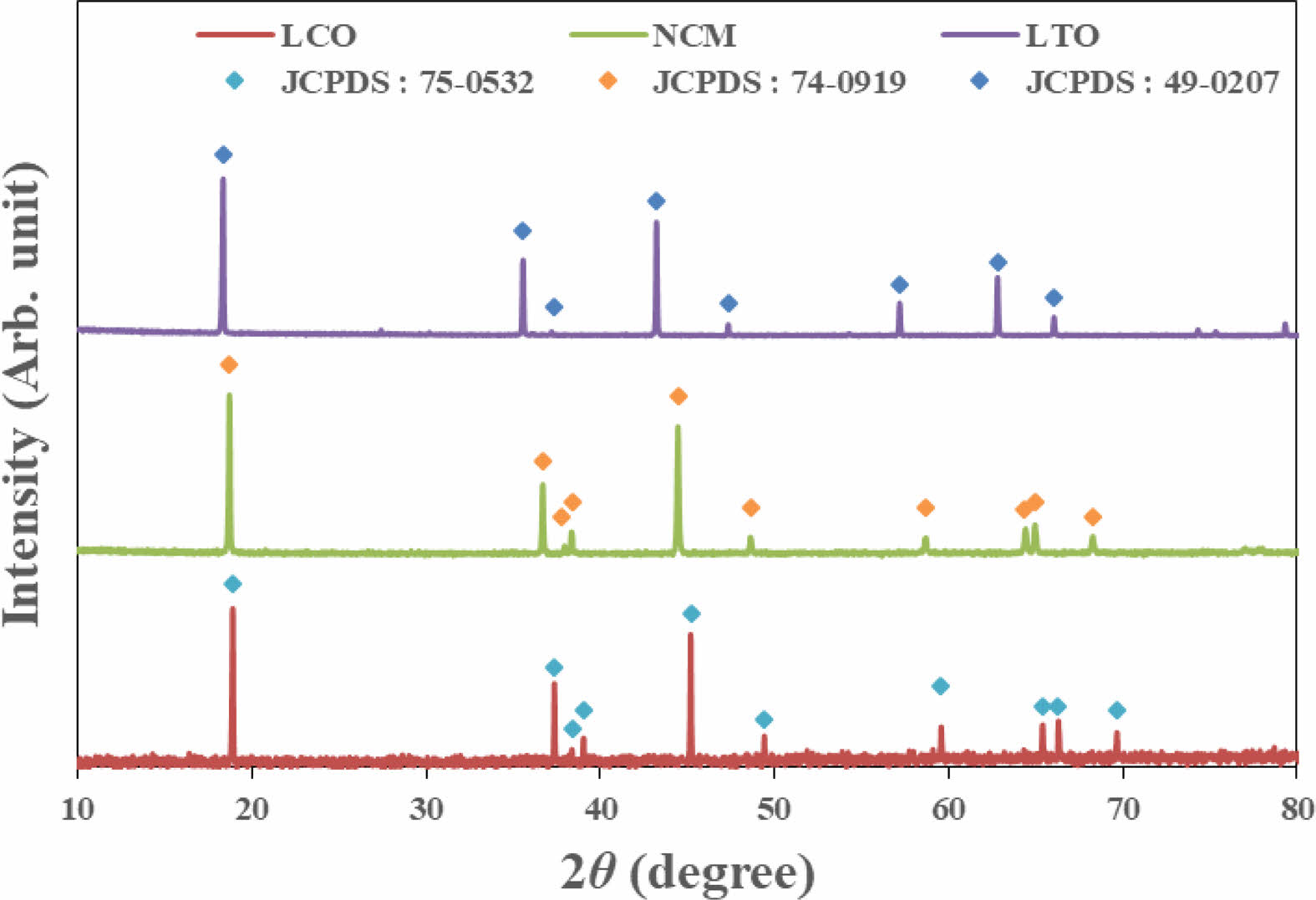
Figure 1 shows the XRD results of the positive active materials LCO, NCM 622 and the negative active material LTO used in the experiment. NCM 622 and LCO are a layered structure based on the R-3m space group and the hexagonal α-NaFeO2 structure, as the peak separation for the (108) and (110) planes was clearly formed near 65o of the layered structure. LTO was 18.4o (111), 35.6o (311) 57.3o (400), 62.8o (333, respectively), it was confirmed that the spinel structure exists as a single phase.
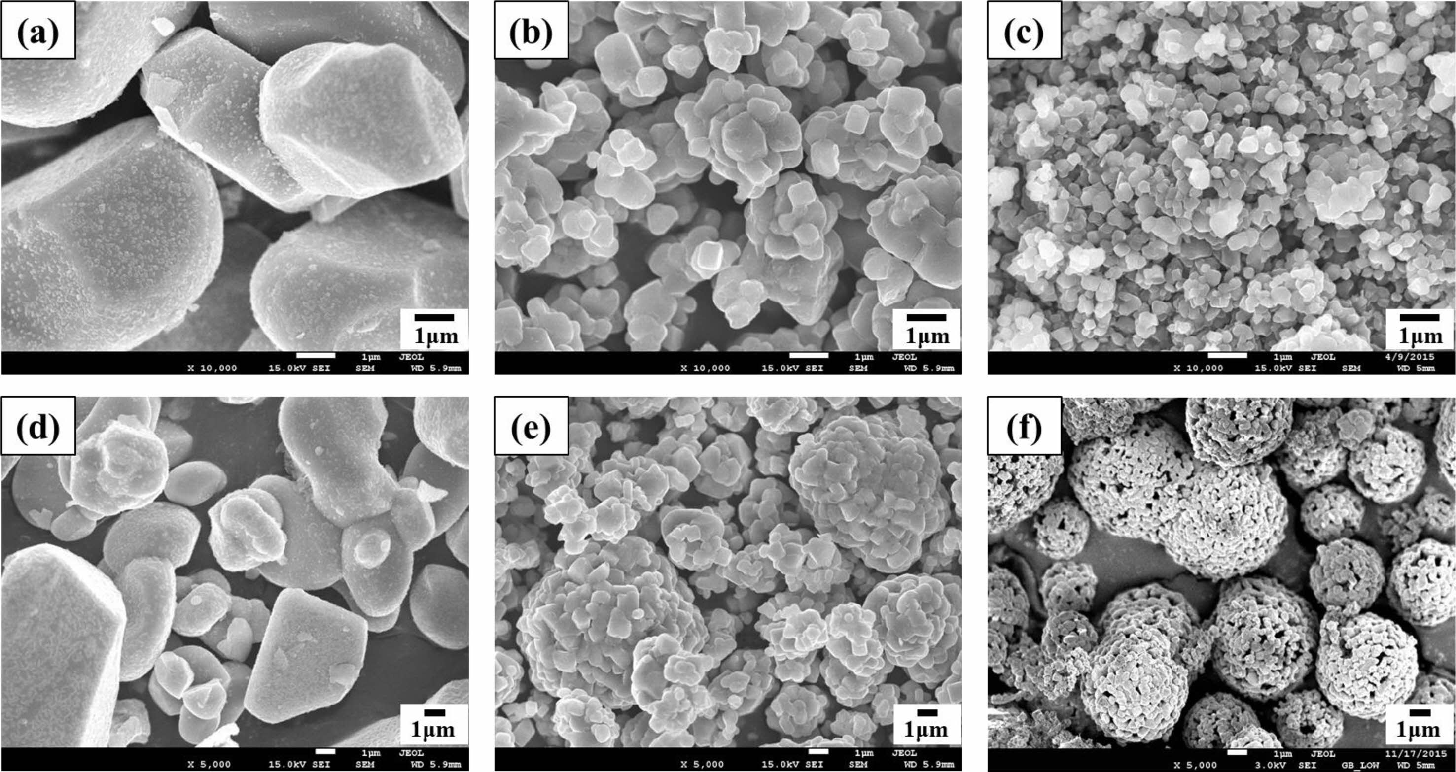
Figure 2 shows the microstructures of the LCO, NCM 622 and LTO. The SEM images indicate that LCO exhibit the spherical morphology with average size of 15.2 μm. The SEM images indicate that NCM 622 exhibit the spherical granule morphology with average size of 7.4 μm, which is composed of numerous primary particles with average size ranged from 200 to 300 nm. The average particle size of LTO was 5-8 μm in diameter which were composed of primary particles with average size between 200 and 300 nm.
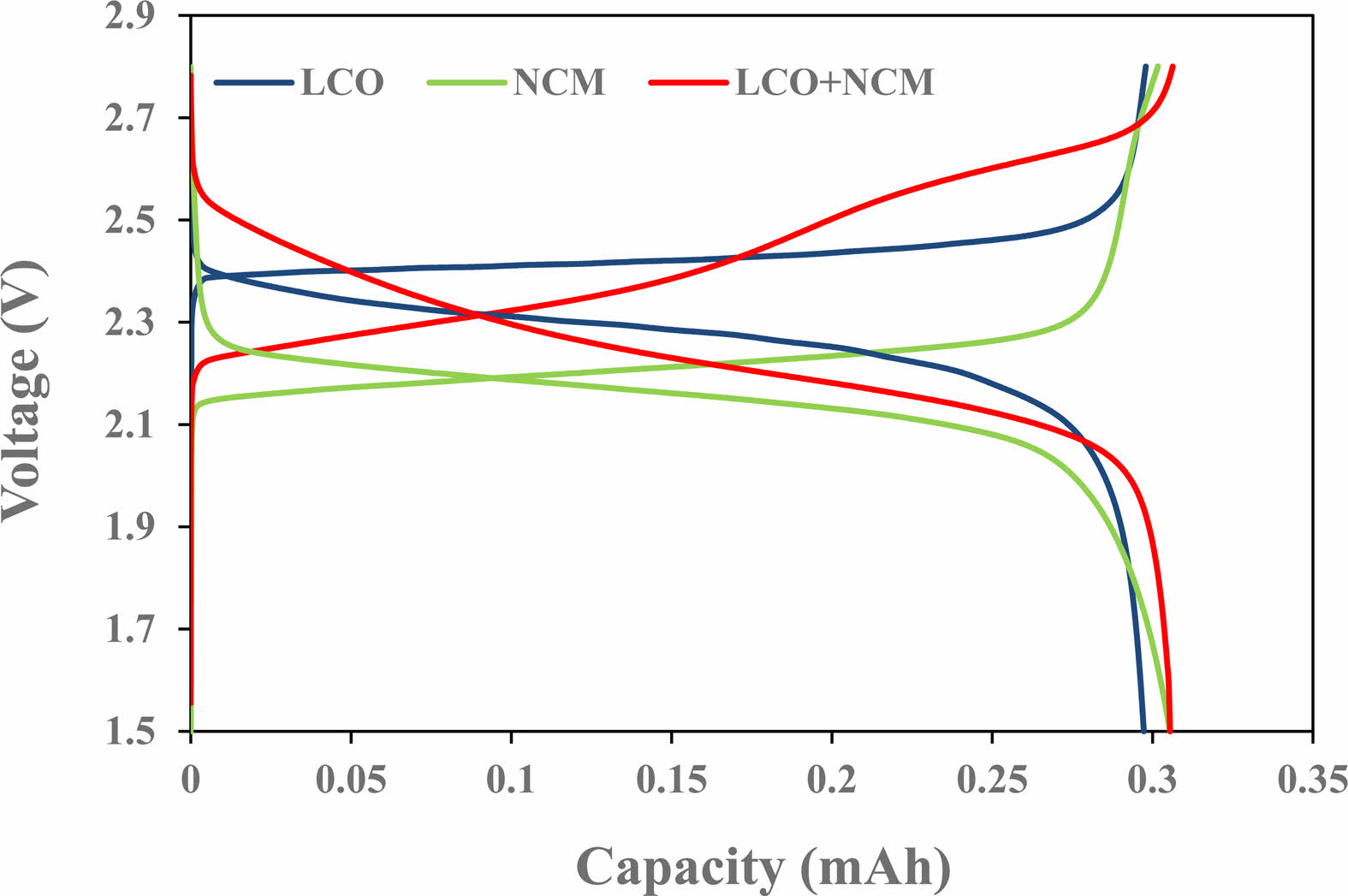
The charge/discharge curves with positive material were shown Fig. 3. It can be seen that voltage curve of the cell combined with LTO is different depending on the positive electrode active material. Most of the capacity was confirmed at 2.36~2.56V for LCO and 2.12~2.32V for NCM 622. When the positive electrode material was used alone, the voltage range was small, so the two materials were mixed to increase the operating voltage, and the operating voltage of the cell to which the NCM and LCO mixed electrode was applied was found to be 2.12~2.6V.
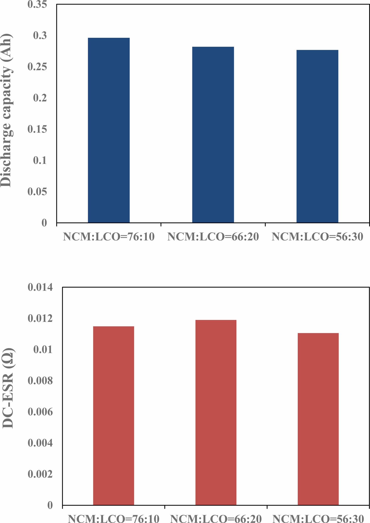
Figure 4 shows the discharge capacity and DC-equivalent series resistance (ESR) of battery capacitor according to the ratio of positive materials. With the LCO content increased, the discharge current of the cell slightly decreased, because the capacity of LCO (145 mAh/g) was smaller than that of NCM 622 (178 mAh/g). The DC-ESR was not remarkably changed as the LCO content increased.
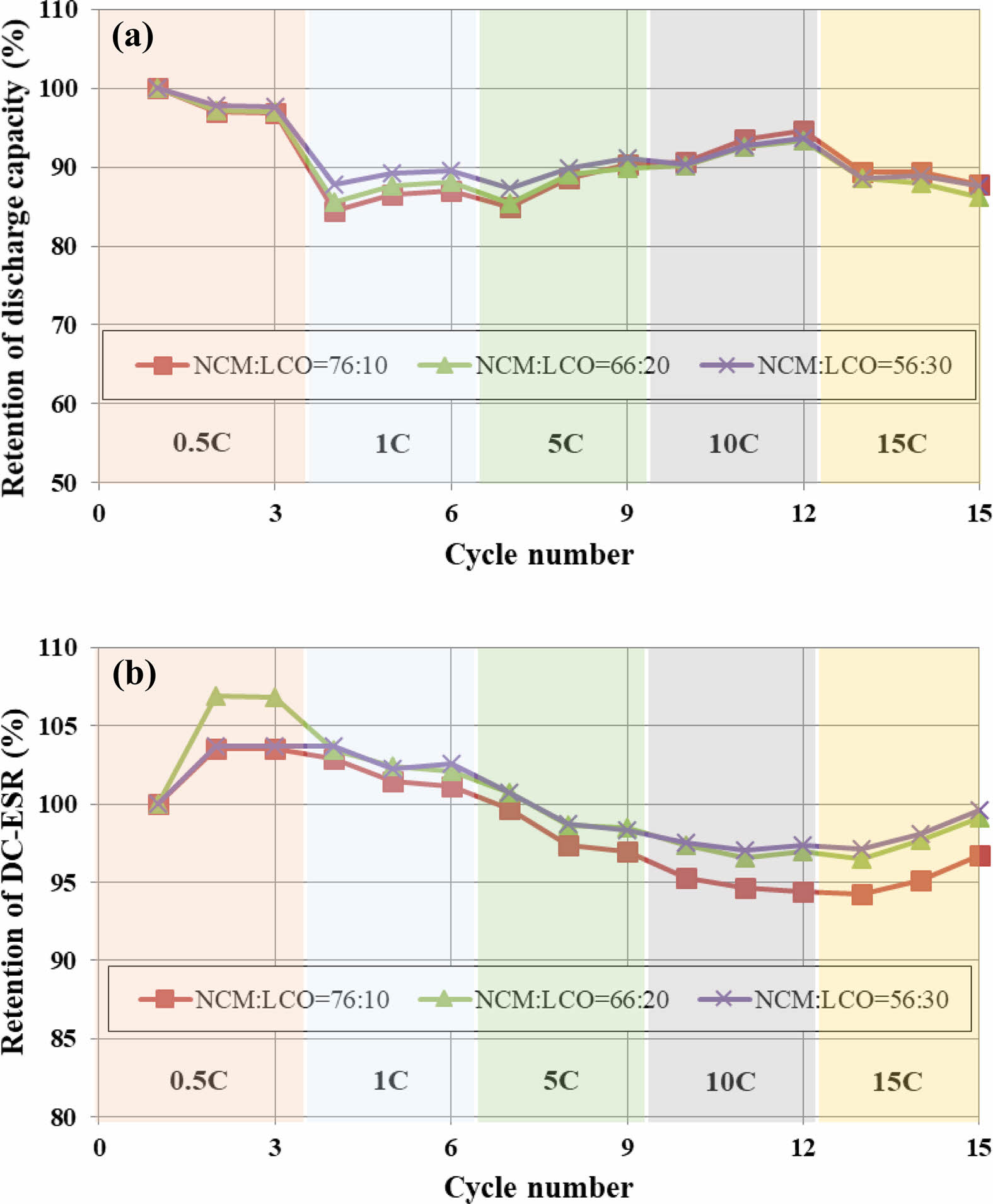
Figure 5 shows the results obtained by charging the cell at 0.5C to 15C-rate, and then maintaining for 10 seconds in the CV region, and then discharging at the same current as the charge current and measuring the C-rate for each three cycles. Three charge/discharge cycles were carried out for each current density. According to the current density, the rate of change in capacity of 15C compared to 0.5C was 86-87%, and the rate of change in resistance was 96-99%. There was almost no difference in the rate of change in capacity and resistance according to the ratio of the positive active material.
The long-term cycle stabilities of battery capacitor according to the ratio of positive materials was shown in Fig. 6. The cycle stability was measured with a current of 10C at room temperature, and the CV time was 10 seconds. In the 5000th cycles, the retention of discharge capacity were 87%, 94% and 81% according to the positive mixing ratio of 76:10, 66:20 and 56:30 respectively. This result was optimized to reduce the stress applied to the anode according to the ratio of NCM and LCO, thereby improving the life characteristics. During charge and discharge, the reaction volume change of the material can be partially compensated resulting in a lowered net volume change. The stress generated inside the battery positive is thus reduced [11].
|
Fig. 1 XRD patterns of LCO, NCM and LTO. |
|
Fig. 2 FE-SEM image of active materials. ((a), (d) LCO, (b), (e) NCM and (c), (f) LTO). |
|
Fig. 3 Charge/discharge curve as a function of the positive active materials. |
|
Fig. 4 Capacities and DC-ESR as a function of the mixing ratio of the positive active materials. |
|
Fig. 5 C-rate as a function of the mixing ratio of the positive active materials: (a) capacity retention. (b) DC-ESR retention. |

|
Fig. 6 Cycles as a function of the mixing ratio of positive active materials: (a) capacity retention. (b) DC-ESR retention. |
In this study, the effect of mixing ratio of positive active material on battery capacitor was investigated. We adjusted the mixing ratio of NCM 622 and LCO to 76:10, 66:20 and 56:30 and the electrical characteristics were evaluated. We found that as the LCO content increases in the mixing ratio of positive active material, the discharge capacity was decreased. The C-rate was measured at 0.5 to 15C, and the retention of discharge capacity of cell with a mixing ratio of NCM 622 and LCO was remarkably not changed according to the change in charge current. After 5000 cycles, retentions of discharge capacity were approximately 87%, 94% and 81% for positive mixing ratio of 76:10, 66:20 and 56:30 respectively. From these results, we can confirm that the cell using (NCM, LCO)/LTO electrode can deliver superior electrochemical performances at the optimized positive mixing ratio.
This work was supported by the Technology Innovation Program (10062226, The development of battery capacitor (58Wh/L) composed of graphene and lithium transition metal oxide based flexible electrode for IoT device) funded By the Ministry of Trade, Industry & Energy (MOTIE, Korea).
- 1. S. Lee, D. Jang, J. Yoon, Y.-H. Cho, Y.-S. Lee, D.-H. Kim, W.-S. Kim, and W.-S. Yoon, J. Electrochem. Sci. Technol. 3 (2012) 29-34.
-

- 2. S.-W. Cho, J.-H. Ju, S.-H. Ryu, and K.-S. Ryu, J. Korean Electrochem. Soc. 13 (2010) 264-269.
-
- 3. S.-M. Kim, B.-S. Jin, G.-J. Park, and H.-S. Kim, J. Electrochem. Sci. Technol. 5 (2014) 87-93.
-
- 4. H.-J. Noh, S. Youn, C. S. Yoon, Y.-K. Sun, J. Power Sources 233 (2013) 121-130.
-
- 5. J. Cho, Y. J. Kim, B. Park, Chem. Mater. 12 (2000) 3788-3791.
-
- 6. Y.-H. Chang and S.-Y. Choi, J. Korean Electrochem. Soc. 10 (2007) 184-189.
-
- 7. S. H. Ju, I.-S. Kang, Y.-S. Lee, W.-K. Shin, S. Kim, K. Shin, and D.-W. Kim, ACS Appl. Mater. Interfaces 6 (2014) 2546-2552.
-
- 8. W. Cho, S.-M. Kim, J. H. Song, T. Yim, S.-G. Woo, K.-W. Lee, J.-S. Kim, and Y.-J. Kim, J. Power Sources 282 (2015) 45-50.
-
- 9. Y. Chen, Y. Zhang, B. Chen, Z. Wang, and C. Lu, J. Power Sources 256 (2014) 20-27.
-
- 10. J. W. Seok, J. Lee, T. Rodgers, D. H. Ko, J. H. Shim, Trans. Electr. Electron. Mater. 20 (2019) 548-553.
-
- 11. R. koerver, W. Zhang, L, Biasi, S. Schweidler, A. Kondrakov, S. Kolling, T. Brezesinski, P. Hartmann, W. G. Zeier and J. Janek, Energy Environ. Sci. 11 (2018) 2142-2158.
-
 This Article
-
2022; 23(6): 766-769
Published on Dec 31, 2022
- 10.36410/jcpr.2022.23.6.766
- Received on May 10, 2021
- Revised on Jun 7, 2021
- Accepted on Jul 17, 2021
Services
- Abstract
introduction
experimental
results and discussion
conclusions
- Acknowledgements
- References
- Full Text PDF
Shared
Correspondence to
- Jung-Rag Yoon
-
R&D Center, SAMWHA CAPACITOR, Yongin, South Korea
Tel : +82-31-330-5765 Fax: +82-31-332-7661 - E-mail: yoonjungrag@samwha.com
Clean-Energy Research Institute(CRI), Hanyang University, 222, Wangsimni-ro, Seongdong-gu, Seoul, 04763, Korea
E-mail: jcpr@hanyang.ac.kr