


- Research on the surface settlement and structural force during the construction of the combined structure
Han Xianmina,b and Li Wenjianga,*
aSchool of Civil Engineering, Shijiazhuang Tiedao University, Shijiazhuang, China
bHebei Technology and Innovation Center on Safe and Efficient Mining of Metal Mine, Shijiazhuang, ChinaThis article is an open access article distributed under the terms of the Creative Commons Attribution Non-Commercial License (http://creativecommons.org/licenses/by-nc/4.0) which permits unrestricted non-commercial use, distribution, and reproduction in any medium, provided the original work is properly cited.
The pipe screen structure proposed in this paper is a closed underground steel pipe and reinforced concrete combined structure including 20 steel pipes. The pipe screen - structure method (PSM) mainly includes three construction stages such as steel pipe jacking, steel pipe cutting and concrete pouring, and earth excavation. The surface settlement and structural stress characteristics in the pipe screen structure method's construction process are investigated in this paper using numerical calculations and field tests. The research results show that the pipe curtain structure method can effectively reduce the surface subsidence caused by construction, and the settlement induced in the first stage is the largest, followed by the second stage. The buried pipe curtain structure bears less load according to the measured data. The stress concentration at the connection positions between the steel pipe and the steel plate is noticeable during the steel pipe cutting process. The steel pipe support column mainly bears the pressure, and its bending moment is small. The main reinforced concrete structure is less stressed, and the structural parameters can be further optimized
Keywords: Steel pipe, Reinforced concrete, Surface settlement, Structural stress
The tubular roof method originated in “Antwerp technology” [1, 2] and has been gradually developed and commonly used in Korea [3-6]. The new Tubular Roof method (NTR method) developed from the tubular roof method. After being introduced into China and following some improvements, it was called the Pipe Roof Pre-construction Method (PPM) and used to construct the Xinleyizhi Station of the Shenyang Subway [7].
After continuous absorption, digestion, and improvement, a design concept innovation was carried out in China on the new pipe curtain method. And then the Pipe Screen-structure Method (PSM) was presented [8, 9].
Unlike other pre-support systems that are simply used as a supplemental measure, the steel pipes in PSM are employed as part of the main construction. In PSM, a number of small spaces are connected to form an underground gallery by cutting the steel pipes and removing the soil between the jacked pipes. Following that, reinforced concrete was poured into the gallery to create a permanent underground structure. Finally, under the protection of the surrounding permanent structure, earth excavation is carried out to form the required space.
In the aspect of pipe screen construction, there are many studies on the relevant jacking force [10, 11]. In terms of construction deformation of the PPM method, Xian Yang et al. studied the characteristics of the surface settlement tank using measured data [12, 13]. For the self-healing or connected capabilities of reinforced concrete structure, few literature can be found on this subject [14-16].
Because there is relatively little research on the construction effects of the Pipe Screen-structure Method, further research on the mechanical effects of group pipe jacking, and the spatial transformation law of structural forces and deformations during the complex construction process is still needed.
Project overview
The north and south line car passages are part of the underground channel project of Yingze Street through Taiyuan Railway Station. The underground project is constructed using the Pipe Screen-structure Method. The channel is orthogonal under the Taiyuan station yard, with the south and north channel axes 346 meters apart. The south channel pipe curtain segment is 105 meters long and the north channel pipe curtain segment is 102.5 meters long.
Design of underground channel
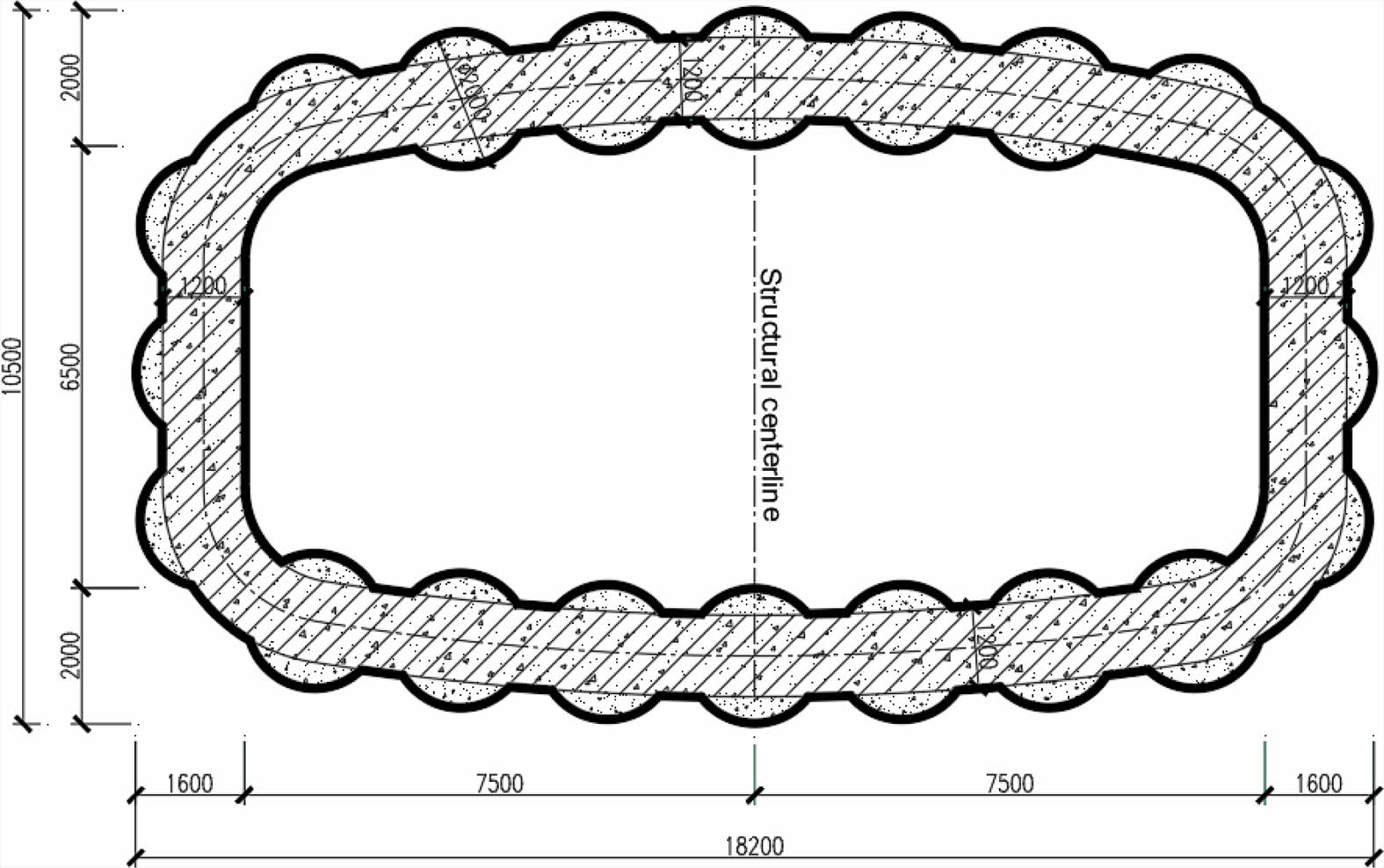
The subterranean route is a double-hole one-way four-lane construction with (3.5 + 3.5 + 3.25 + 3.25) m lane combinations, with a total width of 18.2 m and a total height of 10.5 m. Fig. 1 depicts a cross section of the underground channel.
According to the design size of the headroom in the underground route, 20 steel pipes of Φ2000 × 20 mm were jacked in each passage. And there are 7 pipes in the top and lower parts respectively and 3 pipes on the left and right side walls respectively, with a pipe net spacing of 165~265 mm.
Stratigraphic features
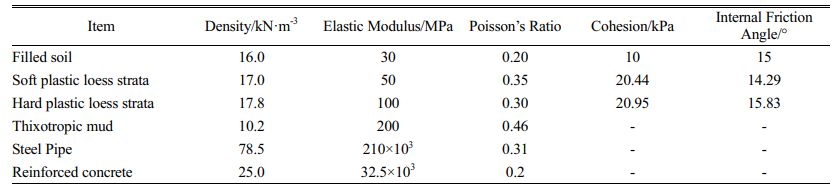
From top to bottom, the artificial fill layer and new loess of the fourth alluvial layer are involved in the passage project. And the pipe jacking mainly traverses the loess layer. The fill layer has a depth of 0~4.6 m, the soft plastic new loess layer has a depth of 3.5~15.4 m, and the hard plastic new loess layer has a thickness of 12.5~26.6 m. The physical and mechanical parameters of the strata are shown in Table 1.
The groundwater level disclosed by the construction is generally below the channel structure's bottom, and loess has a low permeability.
Relationship between the channel and the platform
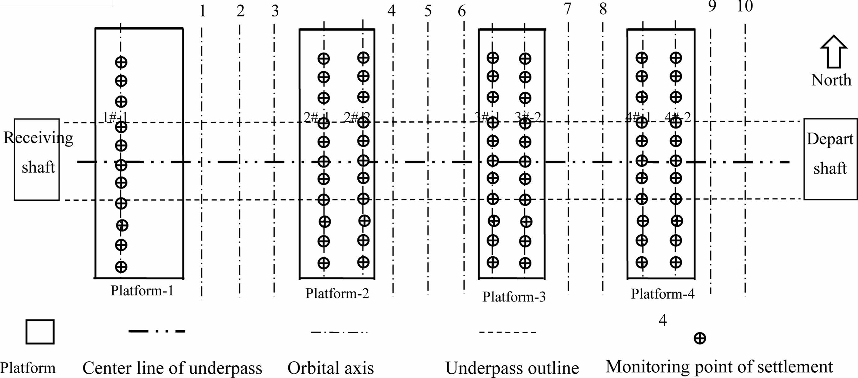
The pipe screen penetrates four platforms and ten tracks, including six arrival and departure lines and four main lines. The pipe screen structure has a minimum net distance of 4.7 m from the platform's top surface. Fig. 2 depicts the plane relationship between the platform, track, and traffic channel planes.
|
Fig. 1 Cross section of the underground channel (mm) |
|
Fig. 2 The plane position relationship between the station platform and the underpass. |
Simulation analysis
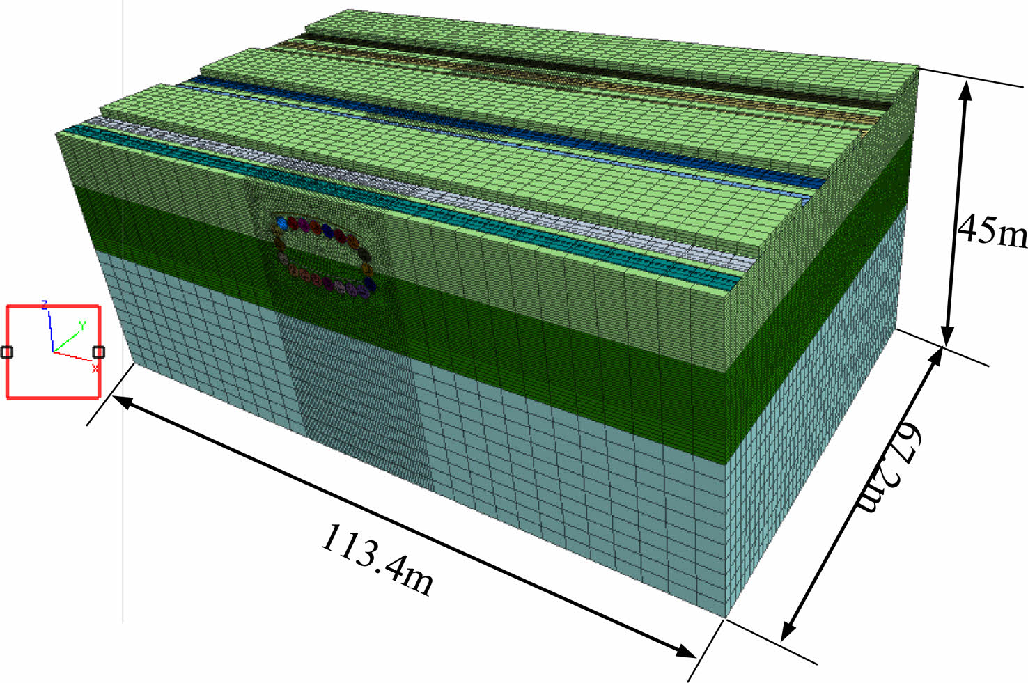
The numerical simulation model is shown in Fig. 3. The physical and mechanical parameters used in the numerical calculations for the stratum, mud and steel pipe are shown in Table 1. The soil layer is modeled in solid units and is defined an elastoplastic material that meets the Moore-Coulomb (M-C) yield criterion. The steel pipe is modeled in shell units, and the thixotropic mud layer is modeled in solid units. Steel pipe and mud layer are defined elastic materials. The thickness of thixotropic mud layer is 20 mm. The main structural concrete poured inside the steel pipe is C40 reinforced concrete, which is simulated by solid element meeting with the linear elastic constitutive relation.
Settlement induced by pipe jacking
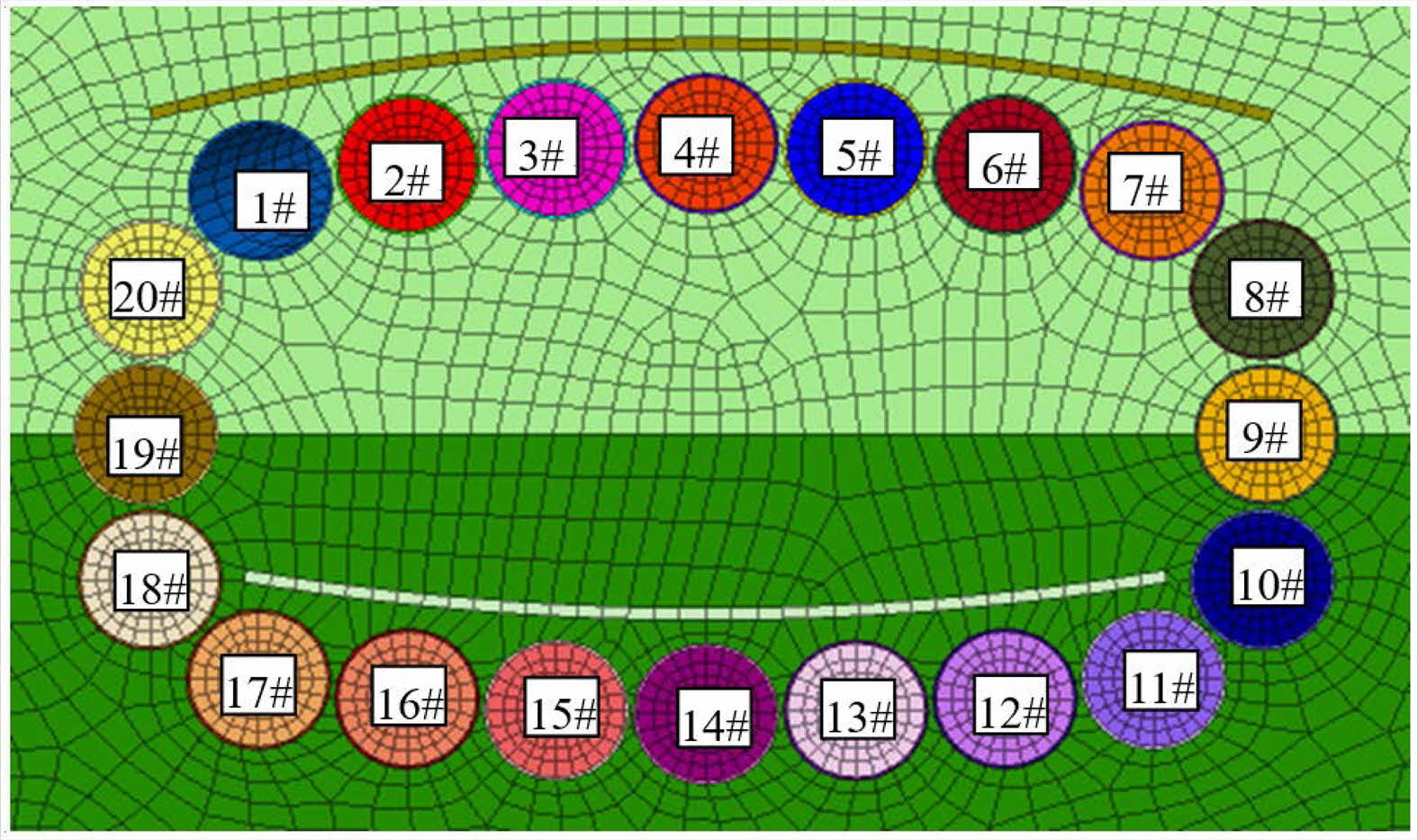
The pipe screen structure is made up of 20 steel pipes, with the upper 7 and lower 7 steel pipes buried at different depths. The upper steel pipes have a buried depth of 4.7 m, and the buried depth of the lower steel pipes is 13.2 m. As the jacking sequences have different impact on the platform ground settlement, it is necessary to conduct the related analysis of ground settlement.
Two different jacking orders are analyzed. Jacking sequence of case one is 7 jacking pipes in the upper part firstly, then 6 jacking pipes in the middle part, and finally 7 jacking pipes in the lower part as illustrated in Fig. 4. And the case two is reverse.
Settlement induced by cutting and support of steel pipes
Steel pipe cutting, soil excavation and steel plate welding between neighboring steel pipes, bracing, and concrete pouring are the next procedures in the pipe screen structure's construction.
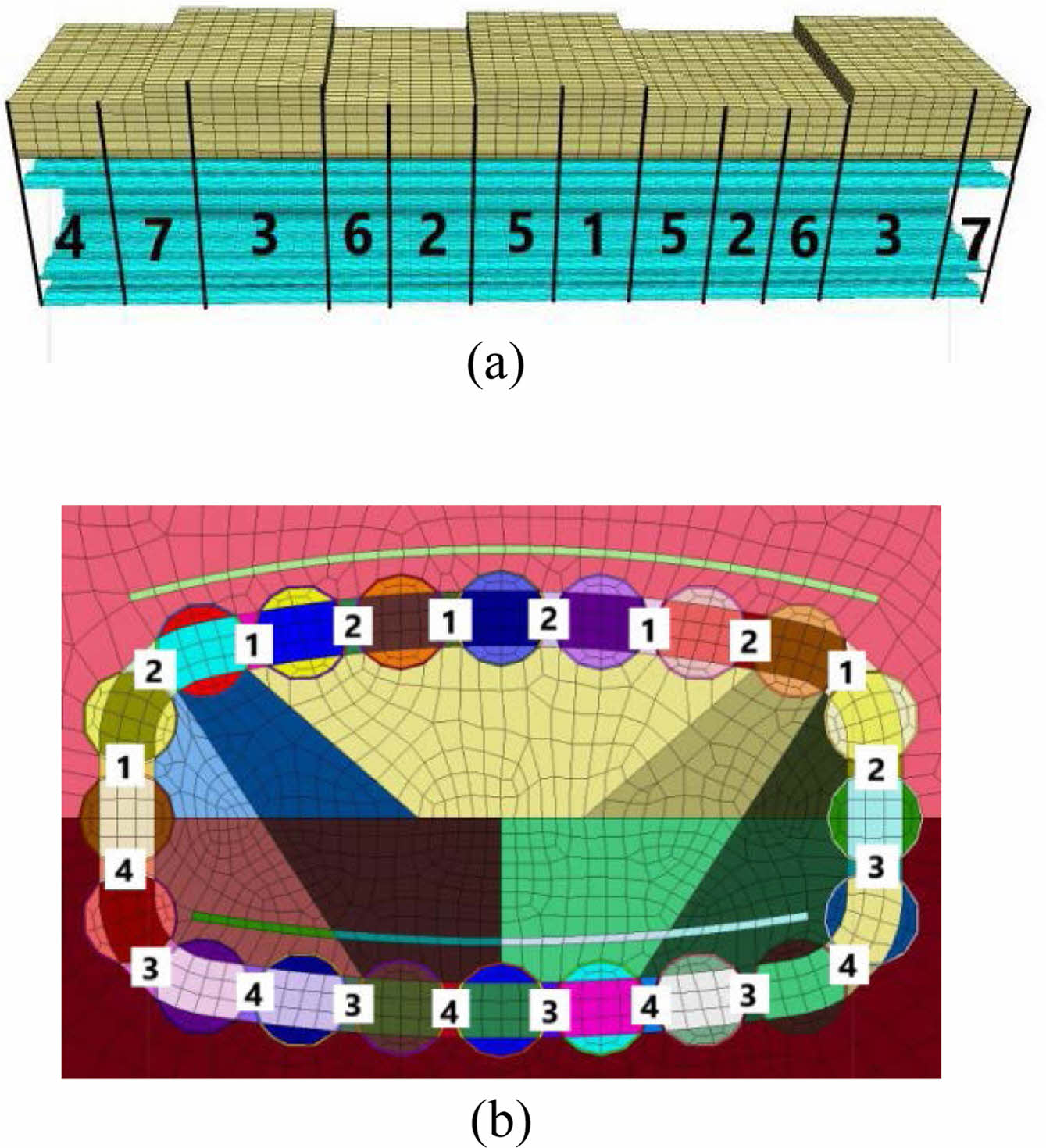
As for the cutting order along the longitudinal direction shown in Fig. 5(a), steel pipes are cut segmentally from the middle of the model to the both ends. Cutting length of steel pipes under the station platform is approximately 8.4 m long, and cutting length under the tracks is approximately 6.0 m long, resulting in a total of 7 cutting cycles.
In the circumferential direction as shown in Fig. 5(b), steel pipe cutting, steel plate welding, and bracing at the upper 1 and 2 parts are done firstly. Then pipe cutting and bracing of the lower 3, 4 parts are done. Single cycle of cutting and bracing is conducted in the order of 1, 2, 3 and 4.
Settlement induced by earth excavation
The excavation of soil inside the pipe screen structure was carried out by mechanical excavation with two steps method, with a excavation footage of 2 m and the step length of 8 m.
Field tests
Surface subsidence
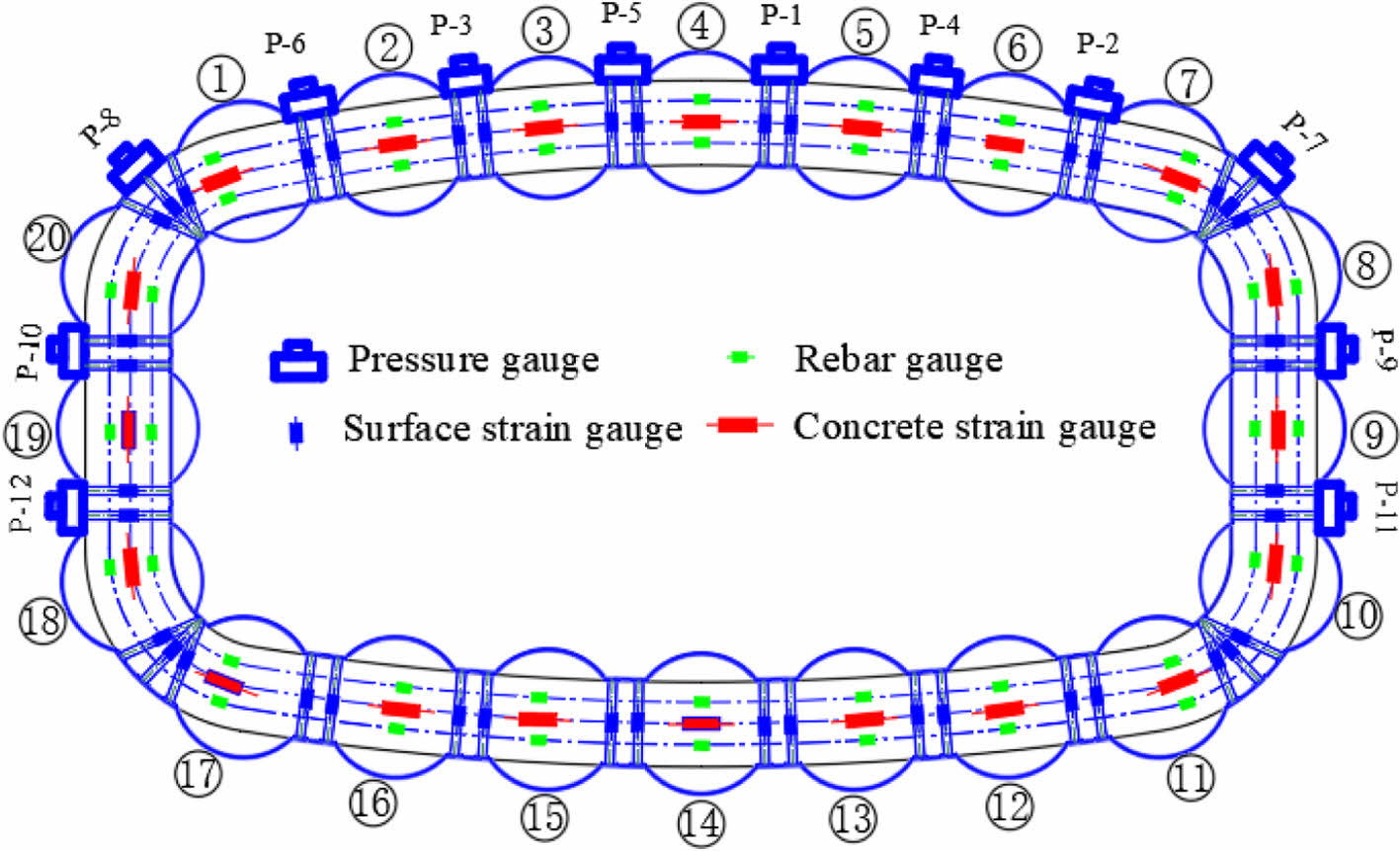
Along the direction perpendicular to the channel, seven measurement lines are set up on the platform, with eleven measurement points per line, as shown in Fig. 2.
Pipe screen structure stress
There are more construction processes and complex structural forces in PSM, and no relevant literature on the structural force characteristics during construction has been presented. In order to reveal the structural stress characteristics during the construction of the PSM, field tests were conducted on soil pressure, axial force of steel pipe support column, concrete stress and rebar stress of the structure.
(1) Monitoring items and test components
Earth pressure behind the connecting steel plate, axial stress of the support column, concrete stress and rebar stress are monitored in the construction process of the structure.
Surface strain gauges symmetrically welded on the outside surface of the steel pipe support columns are used to measure its axial stress. The earth pressure are measured by earth pressure gauges placed behind the steel plate. Concrete strain gauges arranged in a circular direction are utilized to measure the structural concrete stress, and rebar gauges are used to measure the reinforcement stress.
(2) Measurement points arrangement
Fig. 6 shows how the pipe screen's structural stress test elements are laid out. In a typical cross section, there are 12 pressure boxes. The axial stress of the steel pipe support column, the main structure rebar stress, and concrete stress measurement points are all positioned in a full ring.
|
Fig. 3 3D numerical simulation model |
|
Fig. 4 Pipe numbering in pipe curtain jacking. |
|
Fig. 5 Order of steel pipe cutting and bracing. (a) longitudinal, and (b) circumferential. |
|
Fig. 6 Schematic diagram of test elements layout |
Numerical simulation results
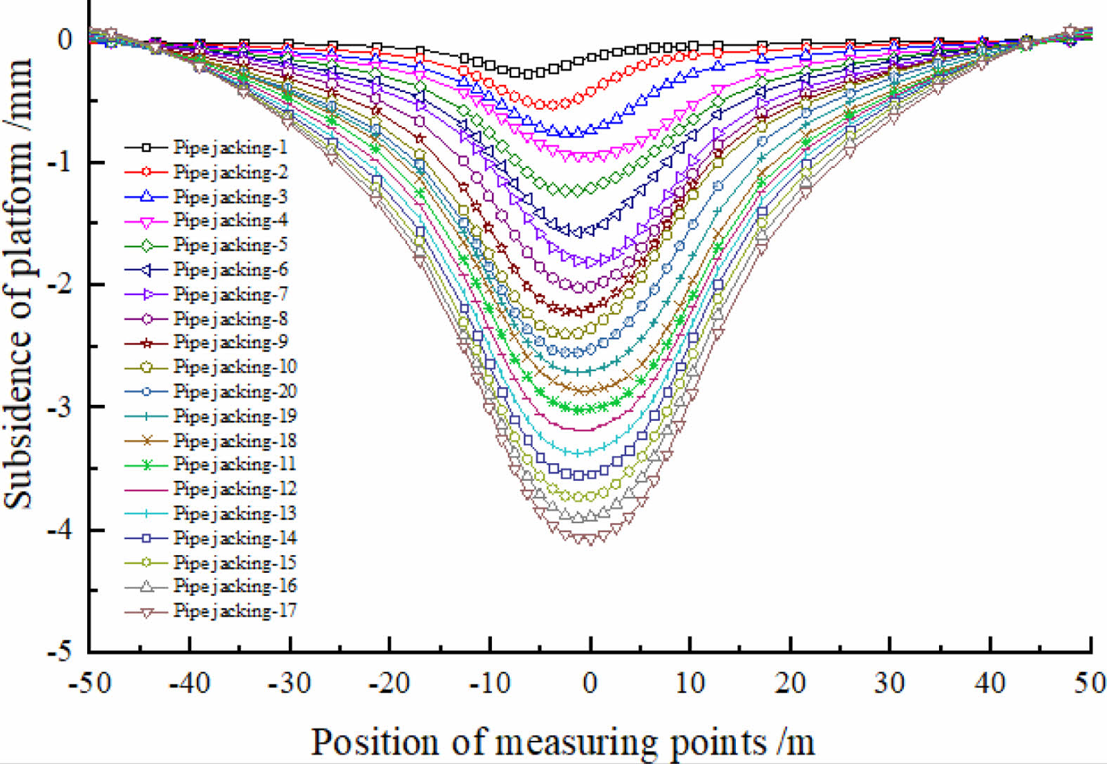
Settlement induced by pipe jacking
The calculation results are shown in Fig. 7 and Fig. 8. The deformation statistics are shown in Table 2.
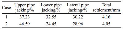
It can be concluded that: ①The transverse settling tank of ground surface shows a similar Peck curve pattern after multi-pipe jacking. ② The lateral deformation influence scope of pipe jacking on ground surface settlement is about 60 m, i.e., 20 m outside the two sides of the pipe screen structure. That is related to the nature of the stratum and the stratum loss rate. ③During jacking of the group pipes, the maximum settlement position of the ground surface is changing, influenced by the spatial position of each pipe. ④Surface settlement is greater in case one than case two, showing that jacking the lower pipes firstly is beneficial to minimizing surface settlement. ⑤For the reason of different burial depth, the surface settlement influenced by the upper pipe jacking is significantly higher than the lower pipe jacking.
Ground deformation induced by cutting and support of steel pipes
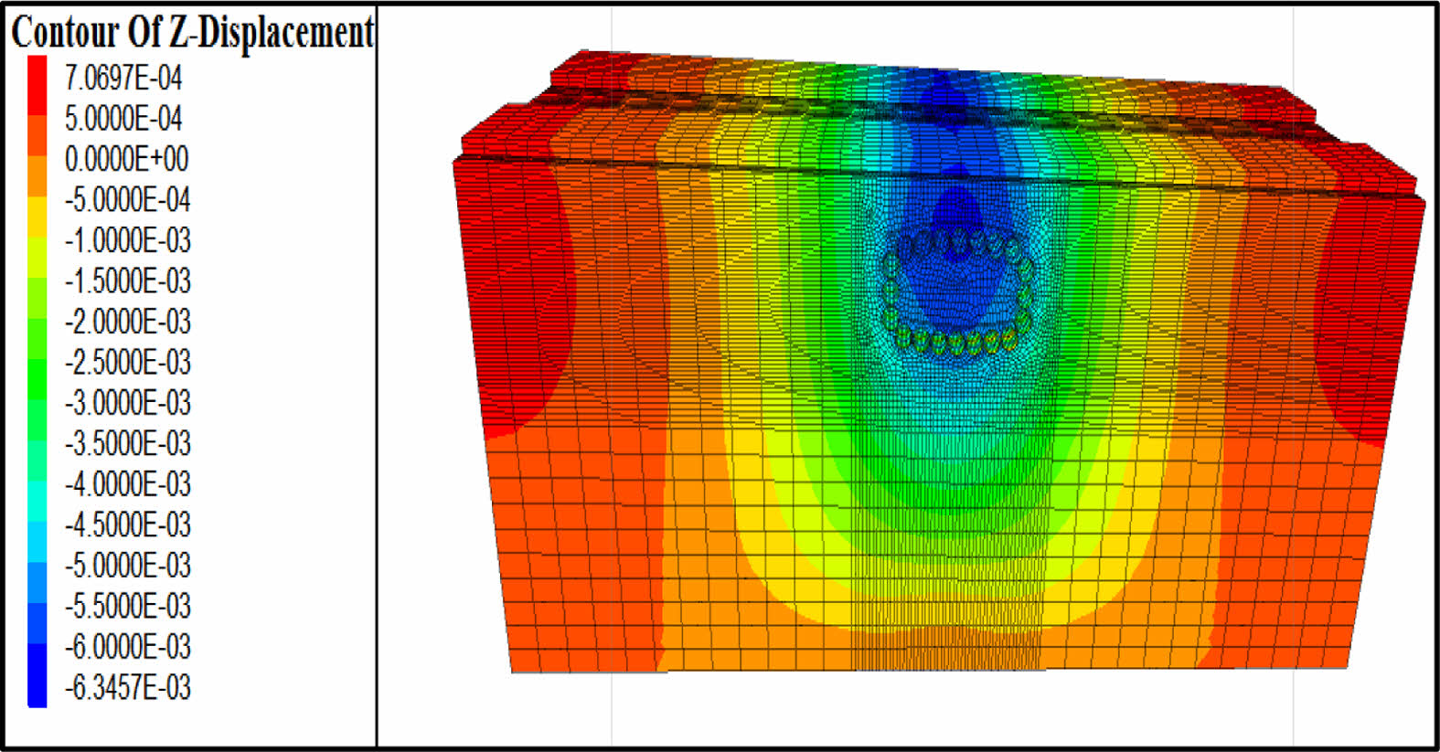
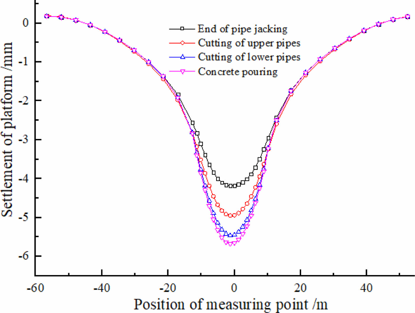
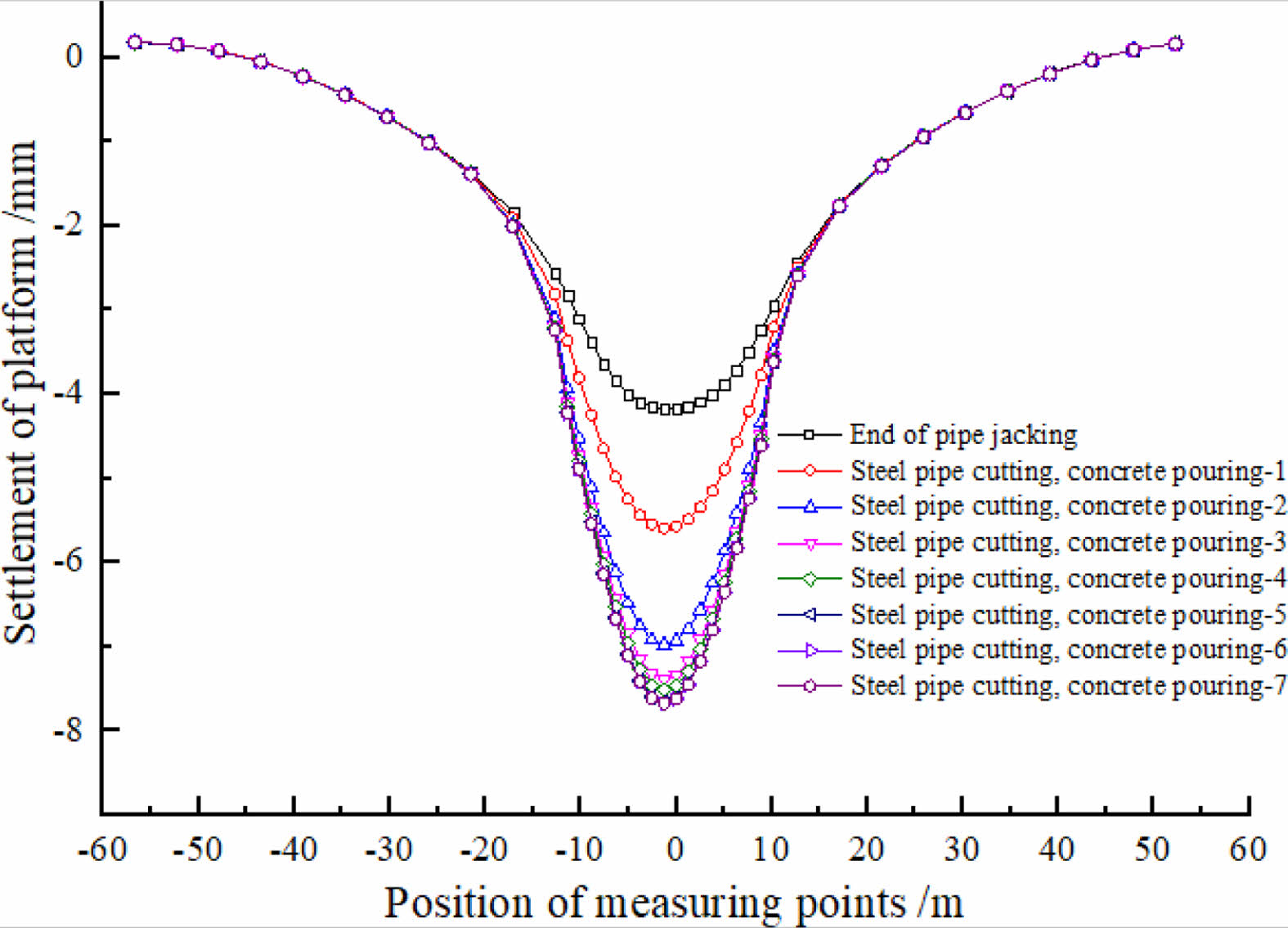
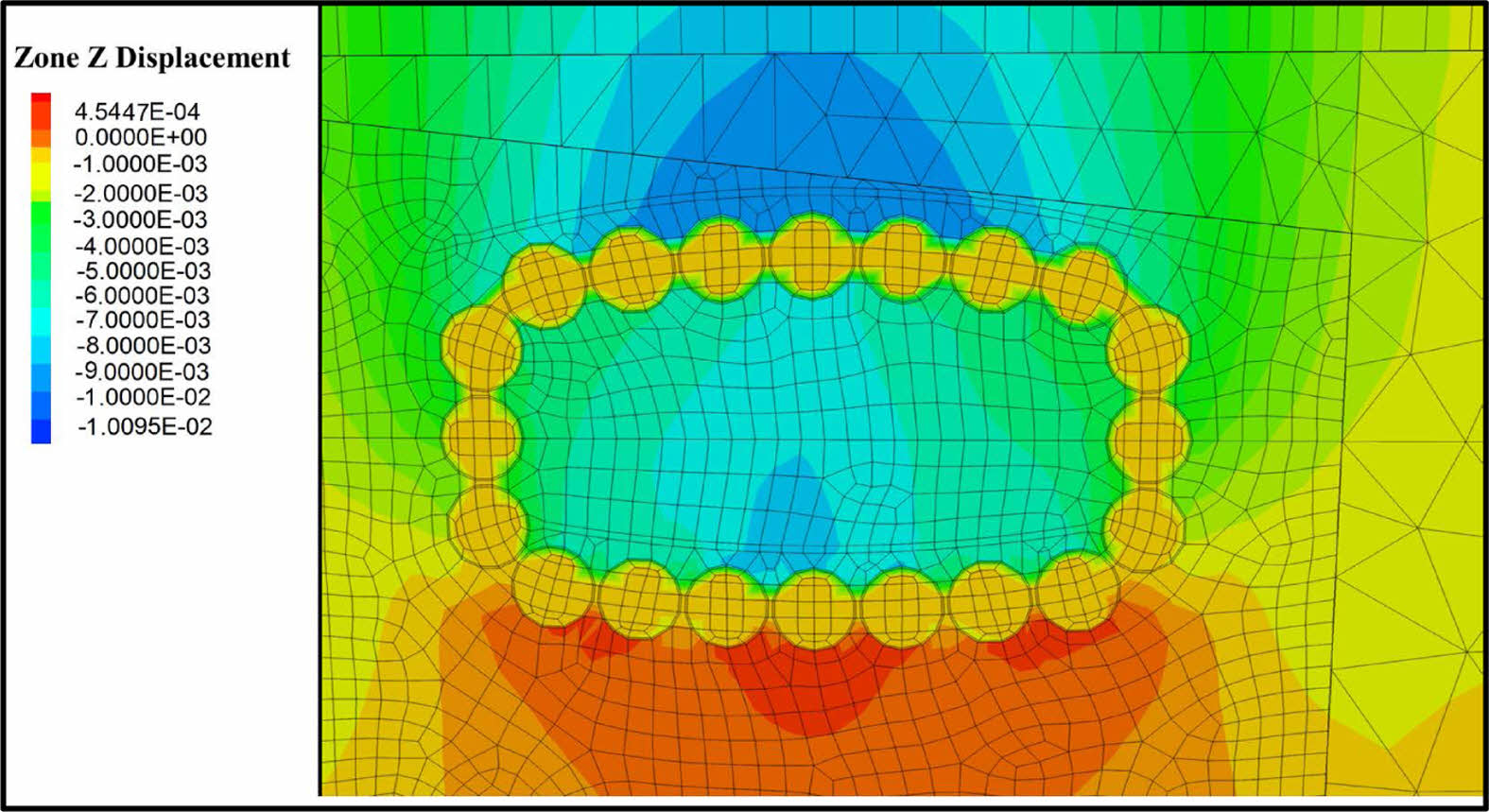
Ground settlement curves under cyclic cutting and bracing are shown in Fig. 9 and Fig. 10. The ground settlement after the completion of steel pipe cutting and concrete pouring is shown in Fig. 11.
It can be seen that: ①In the condition of a single cycle of operation, cutting and bracing of steel pipes has a greater impact on the ground settlement than concrete pouring. After the first cycle of operation, the ground settlement increase from 4.05 mm to 5.67 mm. ②After all the steel pipe cutting and concrete pouring are completed eventually, the maximum settlement amounts to 7.68 mm. ③Because the initial cycle of operation has the largest impact on surface settlement, the length of steel pipe cutting should be reduced on the basis of ensuring efficacy.
Settlement induced by earth excavation
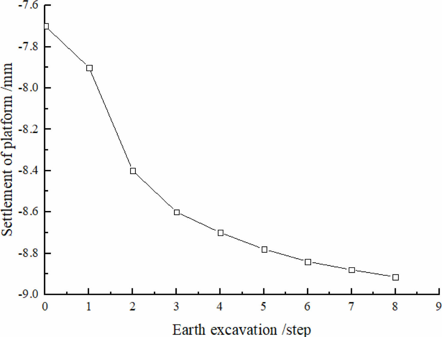
The excavation of soil inside the pipe screen structure was carried out by mechanical excavation with two steps method. Settlement of the ground surface during the earth excavation are shown in Fig. 12.
From the calculation results, it can be obtained: ①With the excavation of earth, the surface settlement gradually increases, but the increment is small, only 1.23 mm; ②The final maximum settlement of the surface is 8.91 mm (i.e. 7.68 mm + 1.23 mm).
Surface settlement variation caused by the construction of the Pipe Screen-structure Method is shown in Fig. 13. Steel pipe jacking, which accounts for about 45% of the total surface settlement, is followed by the steel pipe cutting and concrete pouring stages, which account for about 40% of the settlement, and earth excavation, which accounts for about 15%t of the settlement, as shown in the diagram.
Structural stress during construction
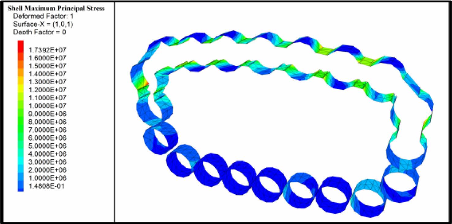
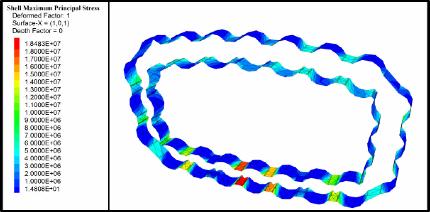
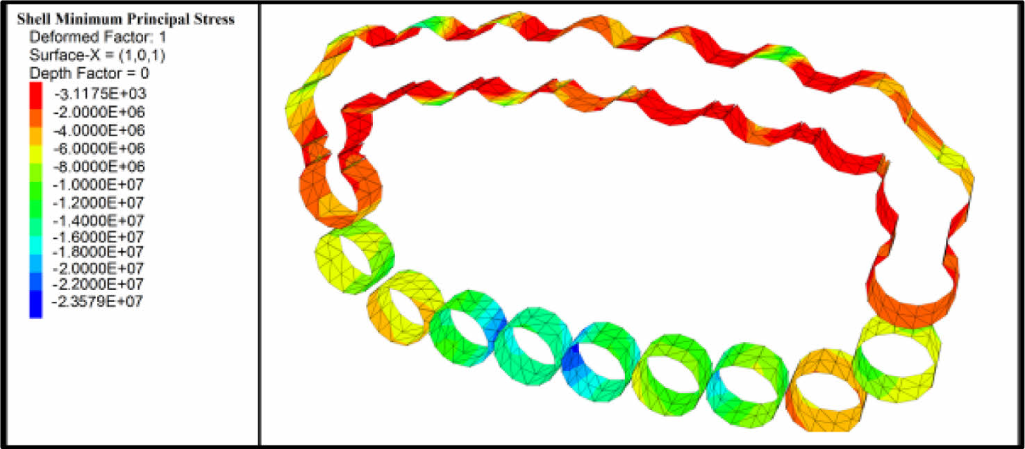
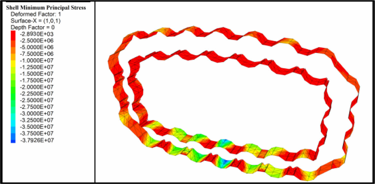
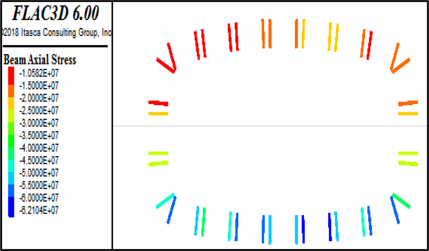
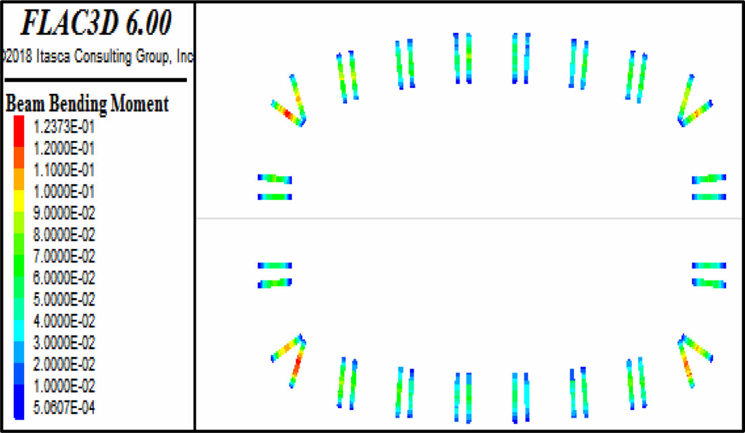
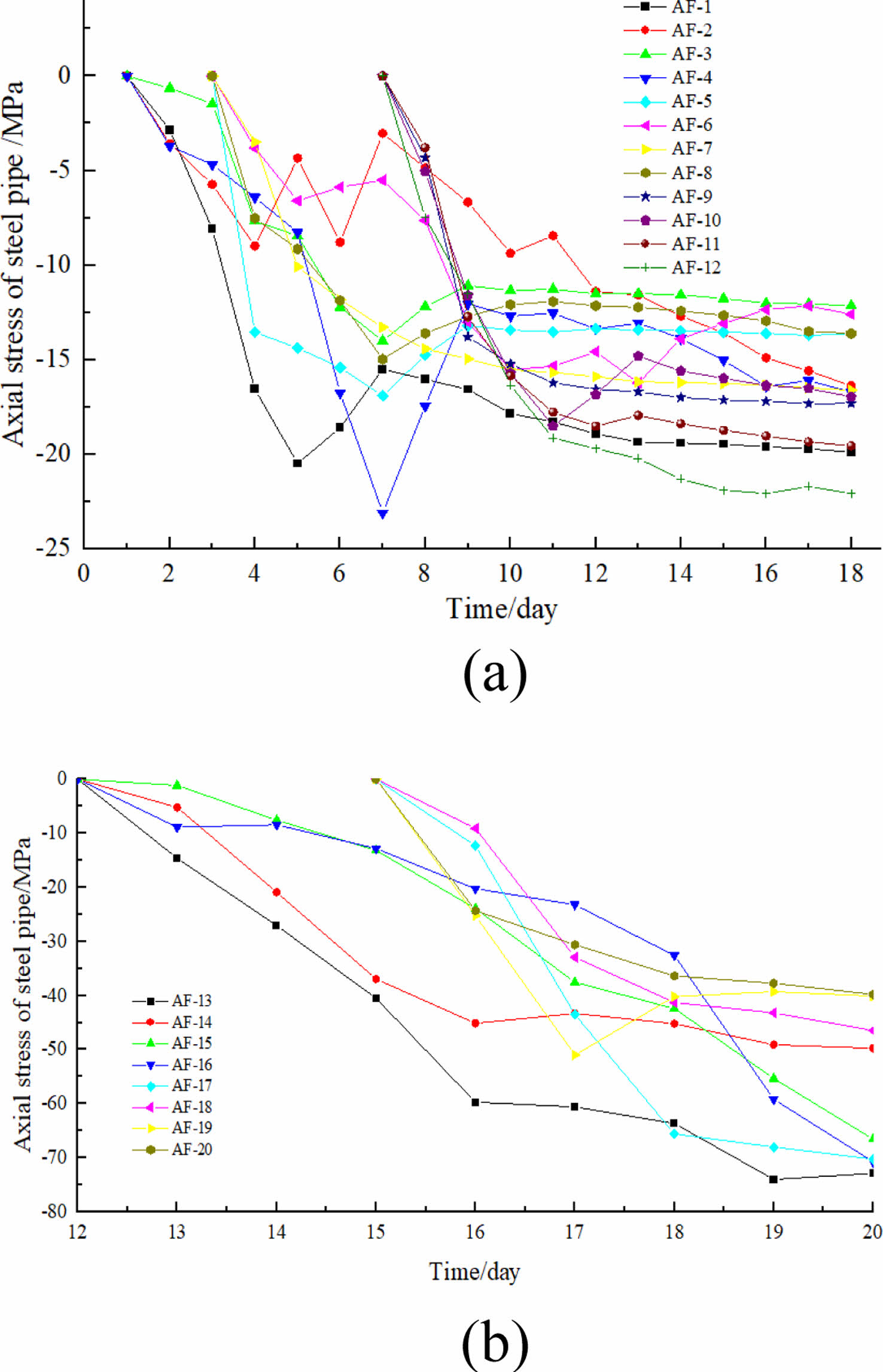
The variation of steel pipe stress during the pipe cutting process are shown in Fig. 14-17, and the internal force of steel pipe support column are shown in Fig. 18, 19.
As shown in the figures: ①The maximum principal stress and the minimum principal stress are located at the welding positions between steel pipe and steel plate. The lower steel pipe cutting could make the transfer of principal stress from top to bottom pipes. ②The maximum principal stress of the connection positions is 18.5 MPa, and the minimum principal stress is -37.9 MPa, which are much smaller than the yield strength of steel. ③The support column's axial compression characteristics are clear. And the axial stress are large, with a maximum axial stress of -62 MPa, but these values are less than the support column's yield strength.
Axial stresses in the bottom support column are greater than those in the top. The bending moment distribution of the support column shows the characteristics of large in the middle and small at the two ends, but the overall bending moment value seems to be small, and its maximum value is located at the four corners of the pipe screen structure. So the support column is mainly subjected to axial pressure.
Field test results
Settlement induced by group pipes jacking
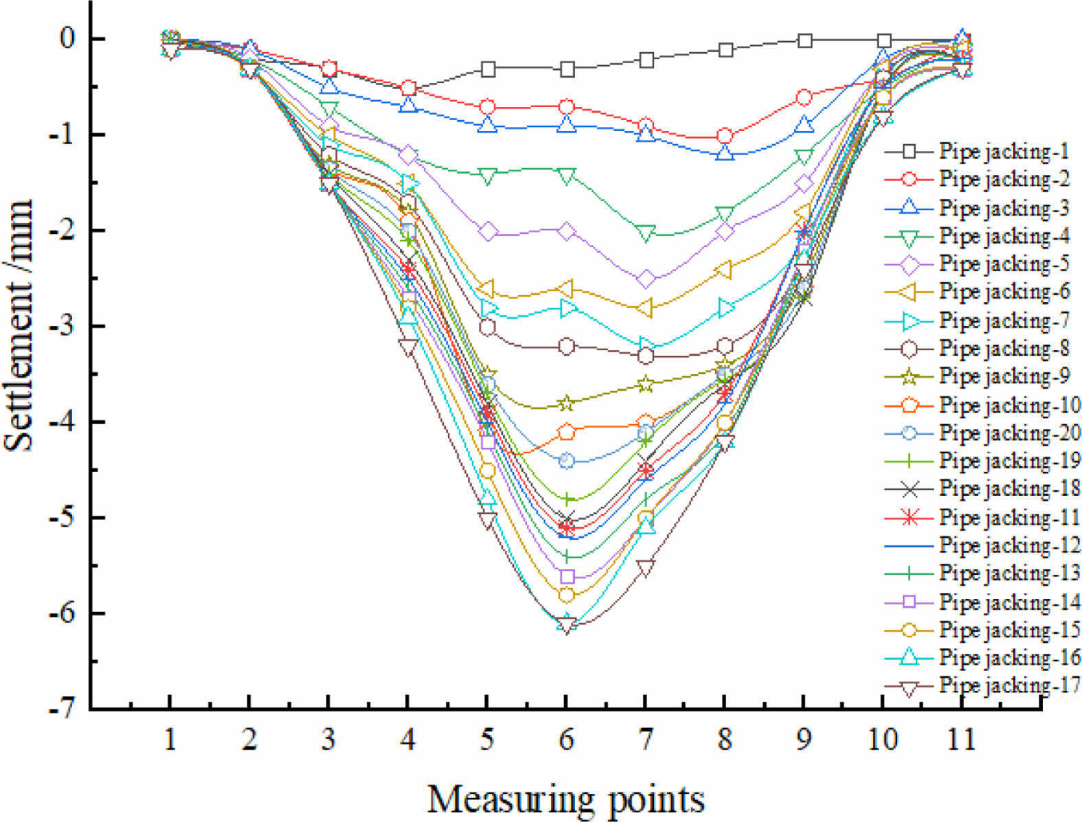
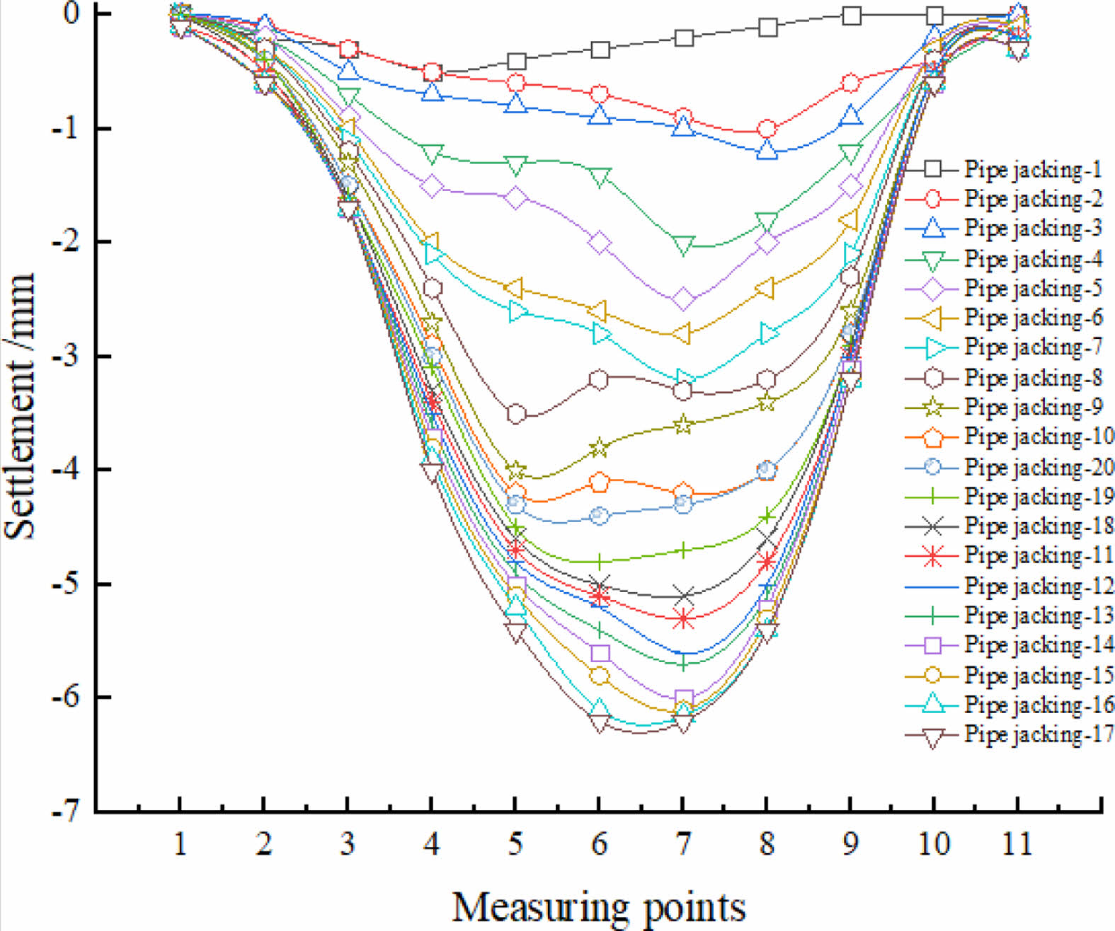
Settlement curves of the typical sections are shown in Fig. 20, 21, and the deformation statistics are shown in Table 3.
The monitoring results show that: ①The actual surface settlement characteristics induced by pipes jacking are basically the same with the numerical simulation results. And the maximum settlement value range from 5.4 to 6.2 mm. ②Because the numerical simulation is difficult to comprehensively consider some construction and external interference factors such as time effect and soil over-excavation, so the measured results are greater than numerical calculation results. ③The measured maximum settlement rate ranges from 0.26~0.41 mm/d, and the average settlement rate is about 0.32 mm/d.
Settlement induced by cutting of pipes, concrete pouring and earth excavation
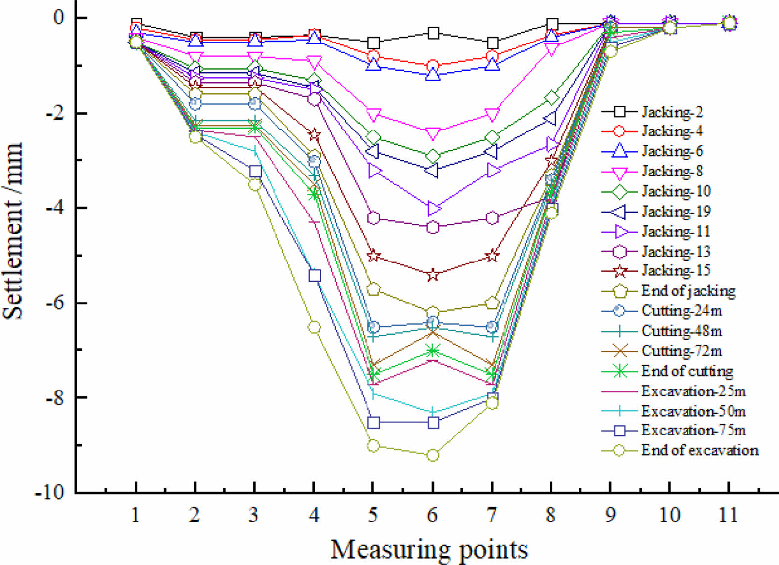
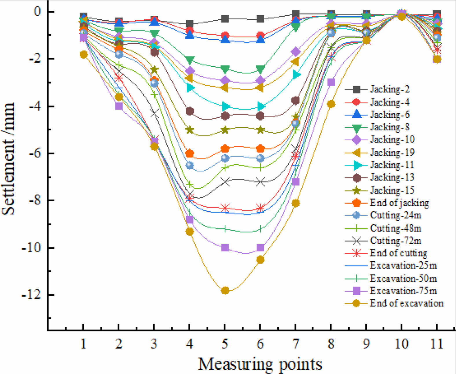
The surface settlement curves of typical sections under steel pipe cutting and earth excavation are shown in Fig. 22, 23.
Monitoring results show that: ①The platform's maximum settlement after the ending of steel pipe cutting and earth excavation is between 8.5 and 11.8 mm, and the average value is 9.8 mm which is greater than the numeral calculation result. The maximum settlement increment caused by cutting is between 2~5 mm, and the settlement increment caused by earth excavation is between 1~4 mm.
②According to the monitoring data, settlement induced by pipe jacking accounts for 45% to 56% of the total, steel pipe cutting and pouring accounts for 30% to 40%, and earth excavation accounts for 10% to 15%.
③In summary, jacking and steel pipes cutting are the main control processes during the construction of the pipe screen.
Earth pressure
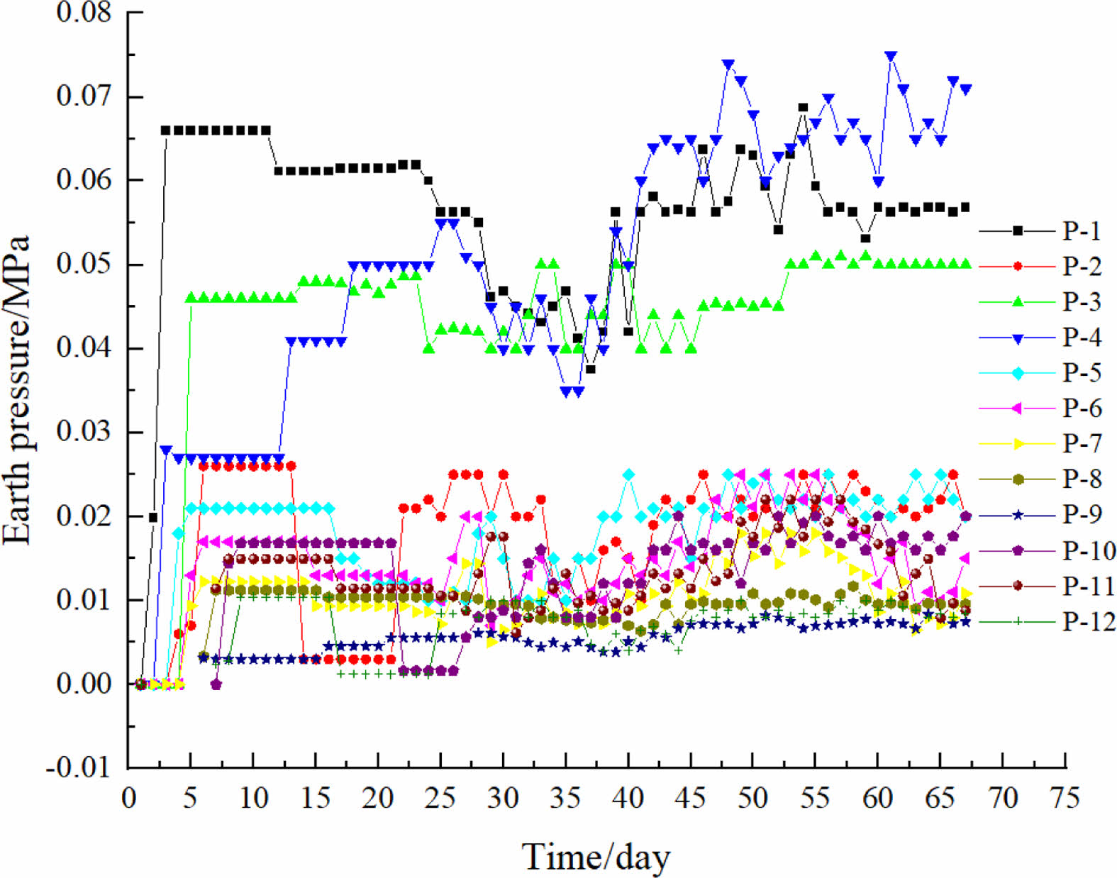
The initial pressure can not be measured after the completion of pipes jacking. So the earth pressure measured is only the pressure increment caused by steel pipes cutting, connection, etc. The actual earth pressure can be calculated by adding the actual measured value to the theoretical calculated load before pipes cutting.
The full soil column theory may be used to determine the soil pressure acting on the top jacking pipes before cutting according to the relevant studies. And coulomb active earth pressure formula can be used to calculate the lateral earth pressure.
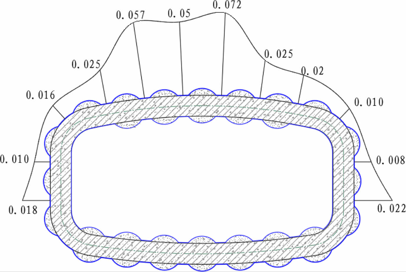
Fig. 24 depicts the earth pressure monitoring results of typical section. Fig. 25 depict the earth pressure distribution rules after the completion of the pipe screen structure.
The structure's measured vertical pressure ranged from 8 to 72 kPa, with an average of about 27.9 kPa. The lateral earth pressure ranged from 8 to 22 kPa, with an average of 12.1 kPa. The lateral earth pressure was about 0.43 times the vertical earth pressure, which was closer to the coefficient of static earth pressure.
Axial stress of support column
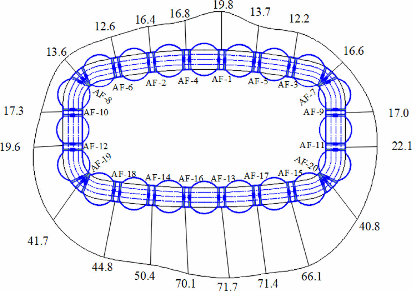
Fig. 26 depicts the change in axial stress in the structure's steel supports. Fig. 27 depicts the axial stress distribution of the steel support across the section. The axial stress of the steel support column ranges from -300 to 150 MPa, with most of them falling between -200 and 10 MPa. The axial stress of the bottom support column is slightly higher than the top.
Concrete stress and reinforcement stress of the main structure
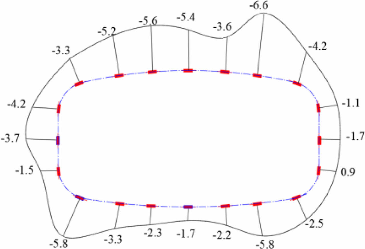
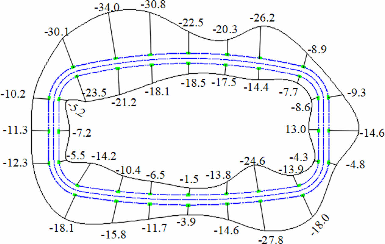
The test results of the concrete stress and rebar stress of the main structure are shown in Fig. 28 and Fig. 29. The measured results show that: ① The main structure's concrete stress ranges from 0 to -6 MPa, with an average value of -3.2 MPa. Tensile stress occurs at few individual points but is less than 1 MPa. ② Rebar stress in the main structure ranges from 10 to -40 MPa, with an average value of -12.5 MPa. And the outside rebar stress is slightly higher than the inner.
On the whole, the load on the pipe screen structure is small, and the structural stress level is low. So the structural safety is high.
|
Fig. 7 Surface settlement during jacking under case one. |
|
Fig. 8 Ground settlement of case one. |
|
Fig. 9 Surface settlement under single cycle. |
|
Fig. 10 Surface settlement under multiple cycles. |
|
Fig. 11 Ground settlement contour after the completion of steel pipe cutting (m). |
|
Fig. 12 Settlement during earth excavation. |

|
Fig. 13 Total settlement curve of PSM. |
|
Fig. 14 Maximum principal stress of the pipe after the upper pipes cutting (Pa). |
|
Fig. 15 Maximum principal stress of the pipe after all pipes cutting (Pa). |
|
Fig. 16 Minimum principal stress of the pipe after the upper pipes cutting (Pa). |
|
Fig. 17 Minimum principal stress of the pipe after all pipes cutting (Pa). |
|
Fig. 18 Axial stress of support columns (Pa) |
|
Fig. 19 Bending moment of support columns (N·m). |
|
Fig. 20 Settlement curves of 1#-1 survey line. |
|
Fig. 21 Settlement curve of 2#-1 survey line. |
|
Fig. 22 Settlement curves of 2#-1 survey lines. |
|
Fig. 23 Settlement curves of 3#-2 survey lines. |
|
Fig. 24 Earth pressure change curves of typical section |
|
Fig. 25 Earth pressure distribution (MPa). |
|
Fig. 26 Axial stress change of the support columns. (a) the top and lateral side, and (b) he bottom. |
|
Fig. 27 Axial stress distribution of the support columns (MPa). |
|
Fig. 28 Concrete stress distribution (MPa). |
|
Fig. 29 Rebar stress distribution (MPa). |
|
Table 3 Statistics of the maximum settlement and settlement rate during the jacking process |

By means of numerical calculations and field tests, the ground deformation, structural force characteristics have been investigated during the construction process of the pipe screen-structure method. The main conclusions are listed as the following:
(1) For the closed pipe screen structure, the sequence of jacking down then up could reduce surface settlement. Among the total settlement caused by pipe screen structure construction, the steel pipe jacking stage causes the most, followed by the steel pipe cutting and concrete pouring stage, and the earth excavation stage causes the least. The monitoring results also show that the construction of the PSM can effectively control the surface settlement.
(2) Due to the reason of burial depth, this pipe screen structure is subjected to small loads. The vertical pressure of the structure is greater than the horizontal, and the measured lateral pressure coefficient is close to the theoretical value of the static earth pressure coefficient.
(3) After steel pipe cutting, the stress concentration phenomenon is significant in the welding position of steel pipe and steel plate. The steel pipe support columns are mainly to bear the axial pressure, and the bending moment is small.
(4) The main reinforced concrete structure has less stress and higher safety, indicating that the structural design parameters may be further optimized.
This work was supported by the State Key Laboratory for Track Technology of High-speed Railway of China Academy of Railway Sciences (Grant nos. 2019YJ196).
- 1. G. Musso, Civ. Eng. 49 (1979) 79-82.
- 2. E. Hemerijckx, Tunnel. Int. 15 (1983) 13-16.
- 3. I.J. Park, Tunn. Undergr. Sp. Tech. 21 (2006) 394-398.
- 4. C.W. Kwak, I.J. Park, S.H. Kim, and J.Y. Kimet, The 4th Dimension of Metropolises (Landon, 2007) p. 513-518.
- 5. S.K. Chang and H.C. Young, Proceedings of the 12th International Conference of the Associated Research Centers for Urban Underground Space, July 2009, p. 21.
- 6. S.Z. Chen and Z.X. Su, Cons. Tech. 41 (2012) 41-49.
- 7. Y.S. Li and K.N. Zhang, Rock Soil Mech. 32 (2011) 3701-3707.
- 8. X.M. Han, X. Liang, and M.Q. Xiao, Railway Standard Design. 65 (2021) 134-140.
- 9. X.M. Han, W.J. Li, and M.Q. Xiao, Tunnel Constr. 40 (2020) 170-178.
- 10. X.B. Ji, W. Zhao, and P.P. Ni, Tunn. Undergr. Space Technol. 90 (2019) 119-130.
-

- 11. X.B. Ji, P.P. Ni, and B. Marco, Underground Space. 4 (2019) 277-288.
-
- 12. Y. Xian and Y.S. Li, Tunn. Undergr. Space Technol. 72 (2018) 210-217.
-
- 13. X. Yang, K.N. Zhang, and Z. Li, Shenyang Univ. Technol. 34 (2012) 469-473.
- 14. H.S. Lee and K.H. Sho, J. Ceram Process Res. 20 (2019) 100-108.
- 15. K.B. Shim, T. kishi, C.S. Choi, and T.H. Ahn, JCPR 16[1] (2015) 1-13.
- 16. H.X.D. Lee, H.S. Wong, and N.R. Buenfeld, Cement and Concrete Research 79 (2016) 194-208.
-
 This Article
-
2022; 23(5): 716-724
Published on Oct 31, 2022
- 10.36410/jcpr.2022.23.5.716
- Received on Apr 24, 2022
- Revised on Jun 21, 2022
- Accepted on Jun 25, 2022
Services
- Abstract
introduction
experimental
results and discussions
conclusions
- Acknowledgements
- References
- Full Text PDF
Shared
Correspondence to
- Li Wenjiang
-
School of Civil Engineering, Shijiazhuang Tiedao University, Shijiazhuang, China
Tel : +86031187935594 Fax: +86031187935594 - E-mail: liwenjiang@stdu.edu.cn
Clean-Energy Research Institute(CRI), Hanyang University, 222, Wangsimni-ro, Seongdong-gu, Seoul, 04763, Korea
E-mail: jcpr@hanyang.ac.kr