


- Effect of hydrofluoric acid chemical corrosion on the grinding of silicon nitride ceramic ball
Ziqiang Gea, Songhua Lia,b,*, Yuhou Wua,b, Yong Shaa, Jian Suna and Junxing Tiana
aSchool of Mechanical Engineering, Shenyang Jianzhu University, Shenyang 110168, China
bNational-Local Joint Engineering Laboratory of NC Machining Equipment and Technology of High-Grade Stone, Shenyang 110168, ChinaThis article is an open access article distributed under the terms of the Creative Commons Attribution Non-Commercial License (http://creativecommons.org/licenses/by-nc/4.0) which permits unrestricted non-commercial use, distribution, and reproduction in any medium, provided the original work is properly cited.
To improve the grinding efficiency of silicon nitride ceramic balls and save processing costs, the pretreatment of hydrofluoric acid that corrodes silicon nitride was introduced into the grinding process based on the chemical characteristics of silicon nitride ceramics that are not resistant to hydrofluoric acid. This paper mainly discusses the effect of hydrofluoric acid pretreatment on the corrosion and grinding of silicon nitride ceramic balls. Through comparison experiments of grinding silicon nitride balls before and after corrosion, it is found that hydrofluoric acid can effectively destroy the structure and reduce the strength of silicon nitride ceramic on the surface. After pretreatment, the grinding removal efficiency of silicon nitride ceramic balls was significantly improved, the ball diameter variation was reduced, and there was no effect on the properties of silicon nitride ceramic. This processing method is expected to be applied to the mass production of silicon nitride ceramic balls
Keywords: Silicon nitride ceramic balls, Hydrofluoric acid, Corrosion, Strength of surface materials, Grinding
Silicon nitride (Si3N4) ceramic has excellent properties, such as low density, high hardness, wear resistance, corrosion resistance, nonmagnetic and nonconductivity properties. It is considered to be the ideal material for the manufacture of high-performance bearing rolling elements and has been widely used in aerospace, machinery manufacturing, the chemical industry and other fields [1-3]. However, due to the high brittleness and wear resistance of Si3N4, it is difficult to process. At present, diamond abrasives or tools are usually used to process Si3N4, which makes the cost large, and the processing is complicated due to the shape characteristics of balls. The traditional processing method of Si3N4 ceramic balls is V-groove grinding, but the surface of balls is prone to defects [4]. To reduce the processing cost and improve the grinding efficiency and the surface quality of Si3N4 ceramic balls, many scholars have performed many studies. Wu et al. [5] proposed the cone-type grinding method. Kurobe et al. [6] proposed the tri-block grinding method. Lv et al. [7] improved Kurobe's grinding method to simplify the structure and formed a rotated dual-plates grinding method. Umehara [8] and Child et al. [9] used the magnetic fluid processing method to process Si3N4 ceramic balls. Lv et al. [10] used diamond abrasive and photosensitive resin to make consolidated abrasive plates, and the removal rate of the consolidated abrasive was approximately 20 times that of the free abrasives. However, the abovementioned methods cannot simultaneously achieve mass production, low cost and high efficiency. A suitable processing technique still needs much research. Si3N4 ceramic materials and other components, such as sintering additives, can react with hydrofluoric acid at room temperature [11-16]. In this study, reducing the strength of the surface material of the Si3N4 ceramic balls was the starting point to analyze the influence of the chemical reaction between hydrofluoric acid and Si3N4 on the processing of balls. The study clarifies the influence of hydrofluoric acid corrosion on the grinding efficiency and surface quality of Si3N4 ceramic balls. The experimental evidence shows that the Si3N4 crystal phase structure of the ceramic balls pretreated with hydrofluoric acid is not affected after the grinding process. It is expected that the pretreatment method will be applied to mass production and other fields with high abrasive costs.
Reaction Mechanism Analysis
The corrosion of substances in acid is characterized by the destruction and reorganization of the original network structure, and the differences in the geometry of the corrosion interface can have a definite effect on the corrosion outcome [17, 18]. Kinetic equations for the corrosion reaction of spherical materials have been studied [19]. The corrosion of Si3N4 by hydrofluoric acid is an interfacial chemical reaction. The corrosion rate does not change with different shapes when the corrosion mechanism is interfacial chemical reaction or mass transfer control. The shape of the ceramic ball surface has essentially no effect on the corrosion reaction, but the corrosion rate will change due to differences in the material preparation process.
The dissolution of glass and other substances in acid will first form a hydration network, and the dissolution of the hydration network then occurs [20, 21]. The reaction of Si3N4 in acid can be understood as the breakage of the covalent bond of Si3N4, which occurs at the thin grain boundary film between two adjacent crystal faces. Si3N4 crystals undergo the breaking of old covalent bonds and the formation of new covalent bonds during corrosion by hydrofluoric acid. The rate of reaction between hydrofluoric acid and Si3N4 is also related to the tightness of the crystal structure network, and hot isostatic pressing (HIP) Si3N4 shows better corrosion resistance.
Under hydrofluoric acid corrosion, the sintering aid in Si3N4 is preferentially corroded and converted to fluoride [22]. Silicon Dioxide (SiO2) in the grain boundaries of HIP Si3N4 ceramic balls can also react with hydrofluoric acid [12, 15]. The chemical equations for the reaction of SiO2 and Si3N4 with hydrofluoric acid are as follows:
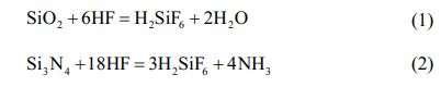
For solid-liquid corrosion, dissolution is controlled by the kinetics of the chemical reaction on the solid surface or by mass transfer and not by the diffusion of the reacting material in the aqueous liquid [23]. Therefore, in the equilibrium expression of equation (2), the formation of intermediate substances is taken into account, and the decomposition of fluorosilicic acid (H2SiF6) into silicon tetrafluoride (SiF4) and hydrogen fluoride (HF) occurs. When the reaction is carried out in aqueous solution, the reaction process can again be decomposed as:

According to equation (2), it can be concluded that NH3 and HF will also react in the reaction process:

Then, the entire chemical equation of the Si3N4 reaction can be integrated as:
Experimental procedure and test method for hydrofluoric acid corrosion
The hydrofluoric acid solution parameters are shown in Table 1, and the physical properties of the Si3N4 materials are shown in Table 2.
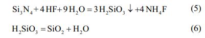
The 70% hydrofluoric acid solution was diluted with deionized water to concentrations of 10%, 20% and 40%. HIP Si3N4 ceramic balls were the object of the experiment. The experimental procedure is shown in Fig. 1. Si3N4 ceramic balls were cleaned with anhydrous ethanol and deionized water before drying and were then placed in 200 ml hydrofluoric acid with various concentrations for 120 hours, the reaction vessel was sealed. At room temperature, Si3N4 reacts readily with hydrofluoric acid [11], so the reaction vessels were placed statically (without stirring) in a constant temperature room at 25 °C.
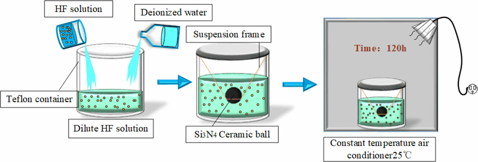
As shown in Fig. 2, hydrofluoric acid first reacts with the exterior layer of Si3N4 ceramic balls, forming a loose corroded layer on the surface (physically appearing white). Then, hydrofluoric acid penetrates into the corroded layer and continues to react with the deeper layer of Si3N4 ceramic balls layer by layer, finally forming a corroded layer with a certain thickness.
A Hitachi S4800 cold field emission scanning electron microscope (SEM) equipped with energy dispersive X-ray spectroscopy was used to observe the surface of the corroded Si3N4 ceramic balls, and XRD was used to analyze the chemical composition of the surface of Si3N4 ceramic balls during the entire corrosion process.
Results and discussion for hydrofluoric acid corrosion
Reaction rate
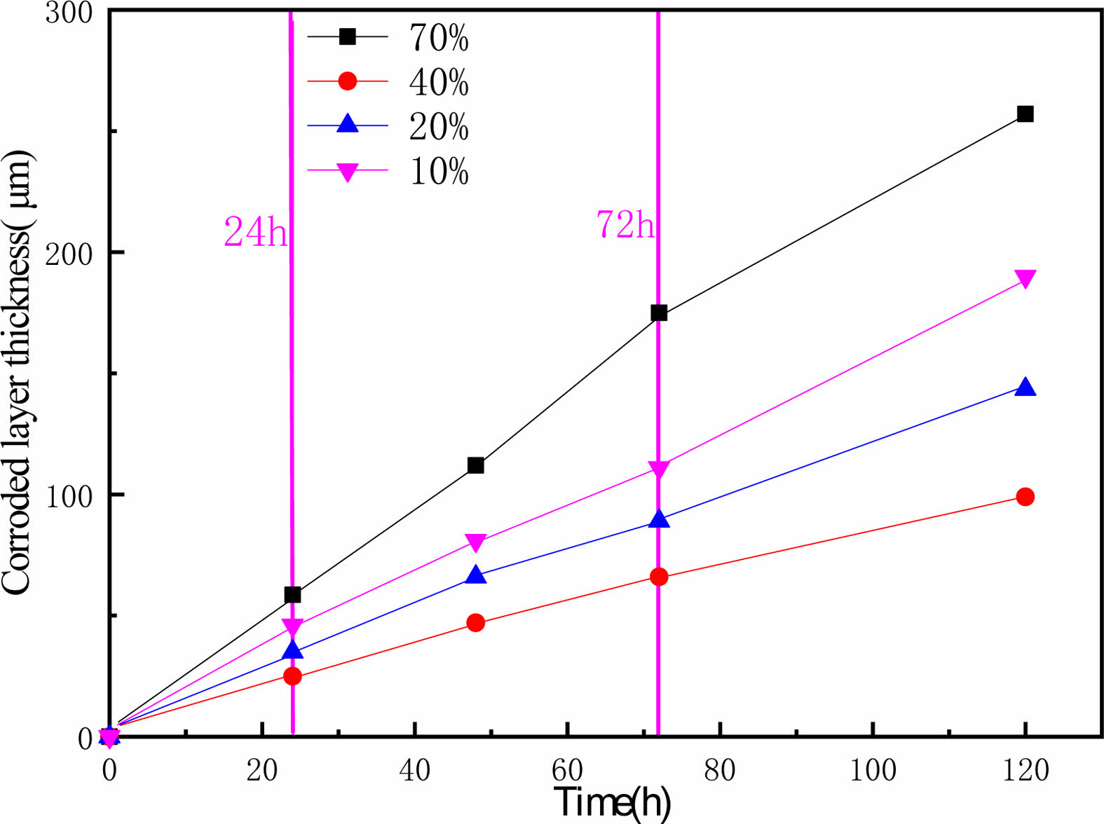
To obtain clearer pictures of the corrosion at each stage, balls were taken from time to time at each concentration, and the thickness of corroded layer was recorded by observing the section surface of Si3N4 ceramic balls with SEM. The thickness of corroded layer was taken to reflect the reaction rate, and the results are shown in Fig. 3.
As Fig. 3 shows, the change in corrosion thickness and time shows a linear trend, indicating that there is no reaction passivation. With increasing time, the overall corrosion rate decreased slightly at each con- centration. As the reaction progresses, the concentration of hydrofluoric acid decreases. Therefore, the reaction rate decreases. Among the measured concentrations, 70% hydrofluoric acid has the fastest corrosion rate of Si3N4, and 10% hydrofluoric acid has the slowest performance. The corrosion rate of Si3N4 ceramic balls in high-concentration hydrofluoric acid is faster, and the corrosion rate increases with increasing concentrations of hydrofluoric acid.
Microscopic morphology of the corroded layer
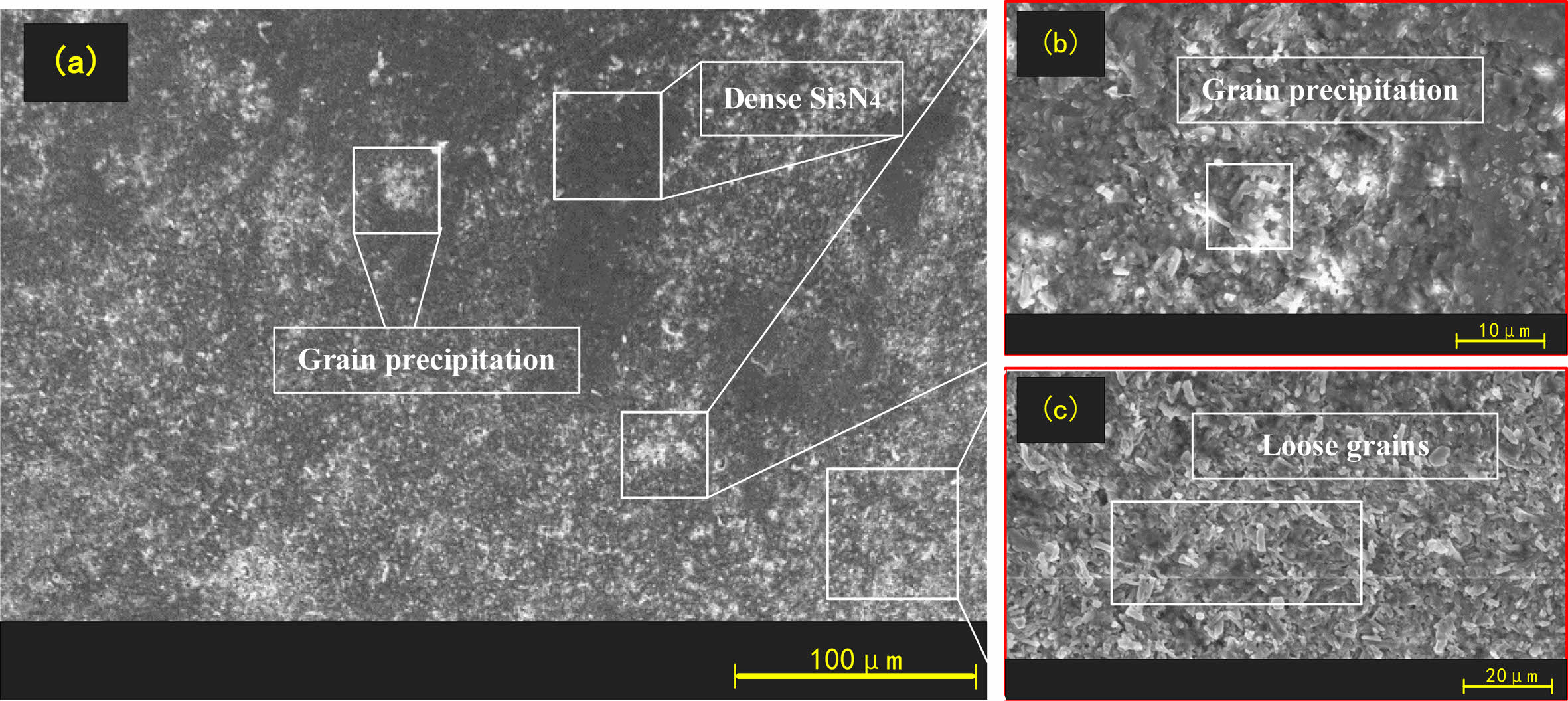
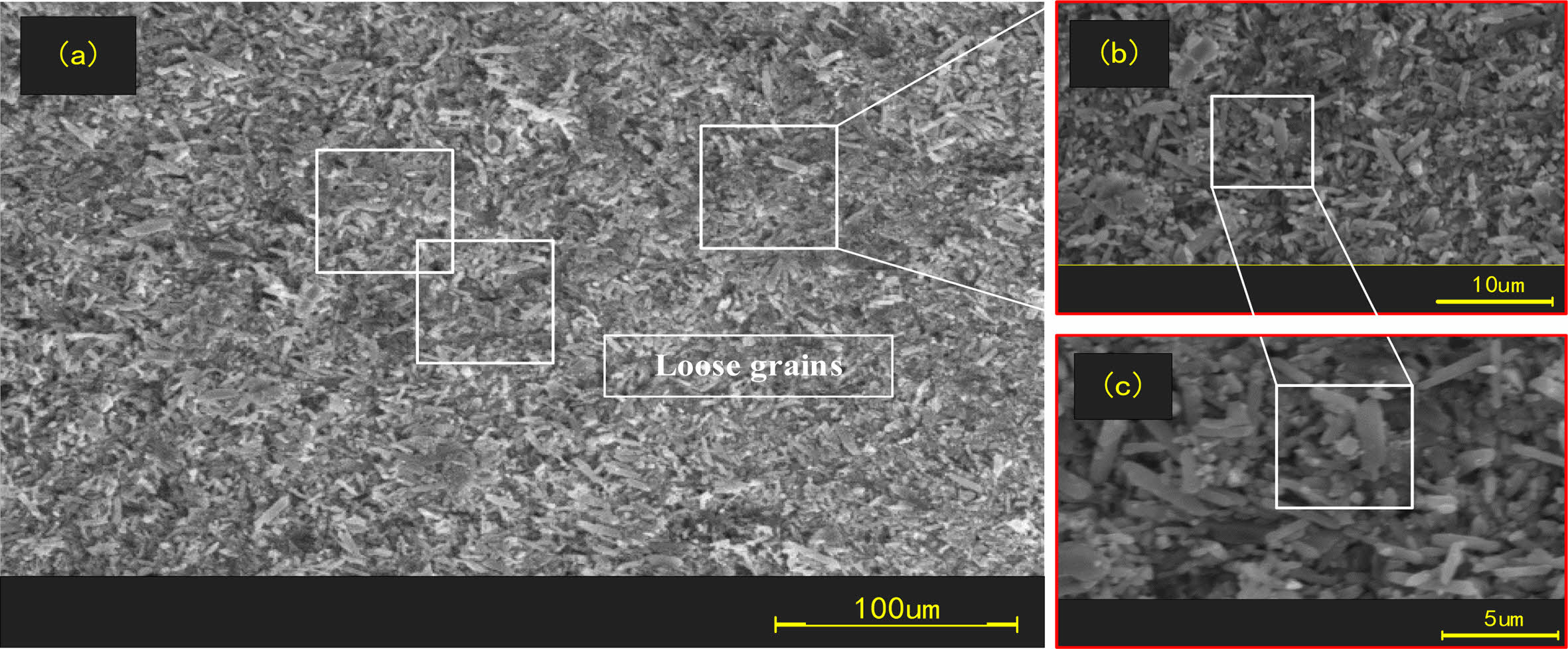
The surface organization of the original balls and corroded balls was observed with SEM, as shown in Figs. 4, 5 and 6.
Fig. 4 shows that the concentration of 10% hydrofluoric acid causes the originally dense Si3N4 crystals to begin to transform into short loose grains. Fig. 5 shows that hydrofluoric acid at a concentration of 40% converts all the Si3N4 on the surface of the ball into obvious short prismatic and granular crystals with loose and irregular distributions. After corrosion with a higher concentration of hydrofluoric acid, we know that the structure of the corroded layer on the surface of Si3N4 ceramic balls is very loose and easier to remove.
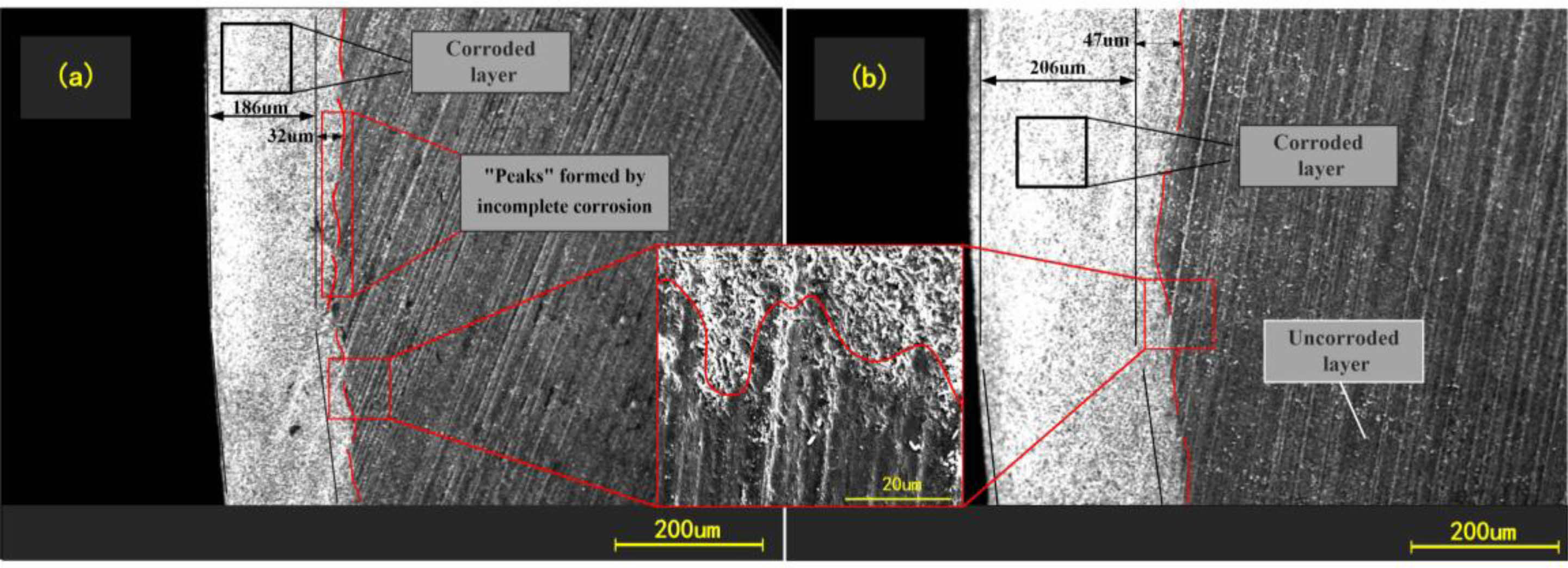
Fig. 6 shows the structure of the corroded layer of Si3N4 ceramic balls. The ball was divided into corroded layer and uncorroded layer based on the reaction that occurred between the Si3N4 and the hydrofluoric acid. The overall distribution of the corroded layer is uniform, with the thickness varying roughly between 200-270 µm. The thickness of the corroded layer of balls under different concentrations of hydrofluoric acid varies. There is also slight variation in the degree to which the material is corroded in the same area. The interface between corroded and uncorroded layers is rugged. The convex part on the surface of the uncorroded layer is interpreted as a “peak” due to internal defects in the Si3N4 ceramic balls, such as pores and microcracks, which allow a small amount of hydrofluoric acid to enter the inside of balls and cause further corrosion reactions, thus making the corrosion reactions in the internal defect areas occur more deeply. Eventually, it appears as a “peak” state at the junction. As shown in Fig. 6, the line marks the “peak”. There is no sign of reaction inside balls, and only a limited thickness of the external surface is affected by the reaction with hydrofluoric acid. Therefore, the author considers a more efficient treatment of this external part while keeping the original characteristics of the ball core intact. We considered using hydrofluoric acid for pretreatment and then grinding Si3N4 ceramic balls. Low-concentration hydrofluoric acid can be used in mass processing to pretreat the original balls. With reference to the data in Fig. 3, the appropriate pretreatment time and hydrofluoric acid concentration can be set according to the thickness of the layer to be ground.
Composition analysis after hydrofluoric acid corrosion
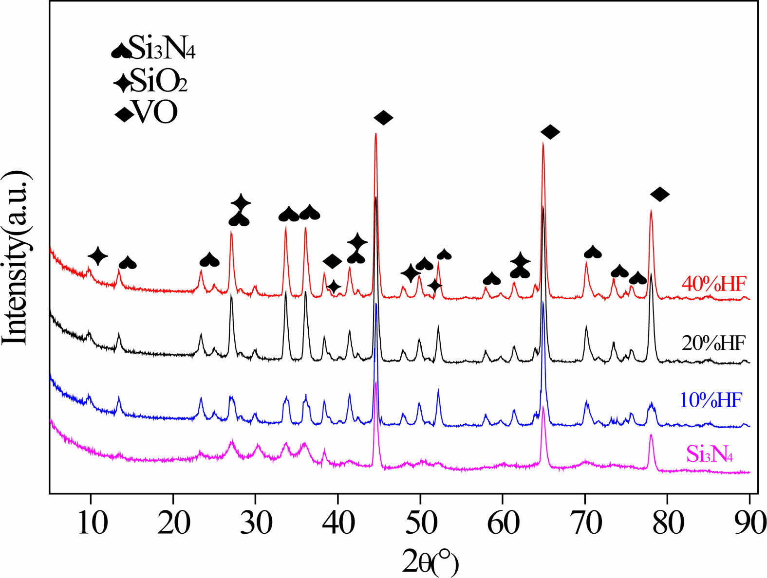
XRD was used to observe the material on the surface of the Si3N4 ceramic balls after corrosion with hydrofluoric acid, and the results are shown in Fig. 7.
Si3N4 diffraction peaks, vanadium monoxide (VO) diffraction peaks and tiny SiO2 diffraction peaks can be observed. Si3N4 is the main component of the original balls, VO is often found as a toughening agent for the material. The peaks with the highest intensities in the Si3N4 samples are those of VO due to the preferred orientation for VO. In the original Si3N4 diffraction pattern, there is almost no SiO2 diffraction peak, which indicates that the SiO2 content in the original Si3N4 ceramic balls is small. The Si3N4 diffraction peaks increase with increasing concentration. The change in the XRD diffraction peaks indicates that the covalent bond is broken and that the hydration reaction occurs. This is because the hydrofluoric acid destroys the originally dense Si3N4 crystal phase, causing it to partially convert into SiO2 and unreacted Si3N4, resulting in grain dispersion and growth.
|
Fig. 1 Schematic diagram of Si3N4 ceramic balls treated with hydrofluoric acid. |
|
Fig. 2 Schematic diagram of the corrosion process of Si3N4 in hydrofluoric acid. |
|
Fig. 3 Corroded layer thickness changes with time and concentration. |
|
Fig. 4 Ceramic balls treated with 10% hydrofluoric acid for 24 h. |
|
Fig. 5 Ceramic balls treated with 40% hydrofluoric acid for 120 h. |
|
Fig. 6 Electron microscopy of corroded layer |
|
Fig. 7 XRD patterns of surface materials. |


Experiment process for grinding
The chemical corrosion analysis of Si3N4 ceramic balls shows that the use of hydrofluoric acid can reduce the strength of the surface material of Si3N4 ceramic balls. This experiment is based on cone-type lapping equipment for grinding processes. The original Si3N4 balls were cleaned and weighed before the experiment, then the original Si3N4 balls soaked in 10%, 20%, and 40% hydrofluoric acid for 120 h were ground. The processing parameters are as follows: speed 200 r/min, load 8 N/ball, abrasive concentration 15% (wt%), grinding time 3 h. After grinding, the Si3N4 ceramic balls were first inspected, and then the balls were finished and inspected.
Results and analysis for the grinding experiment
Grinding rate
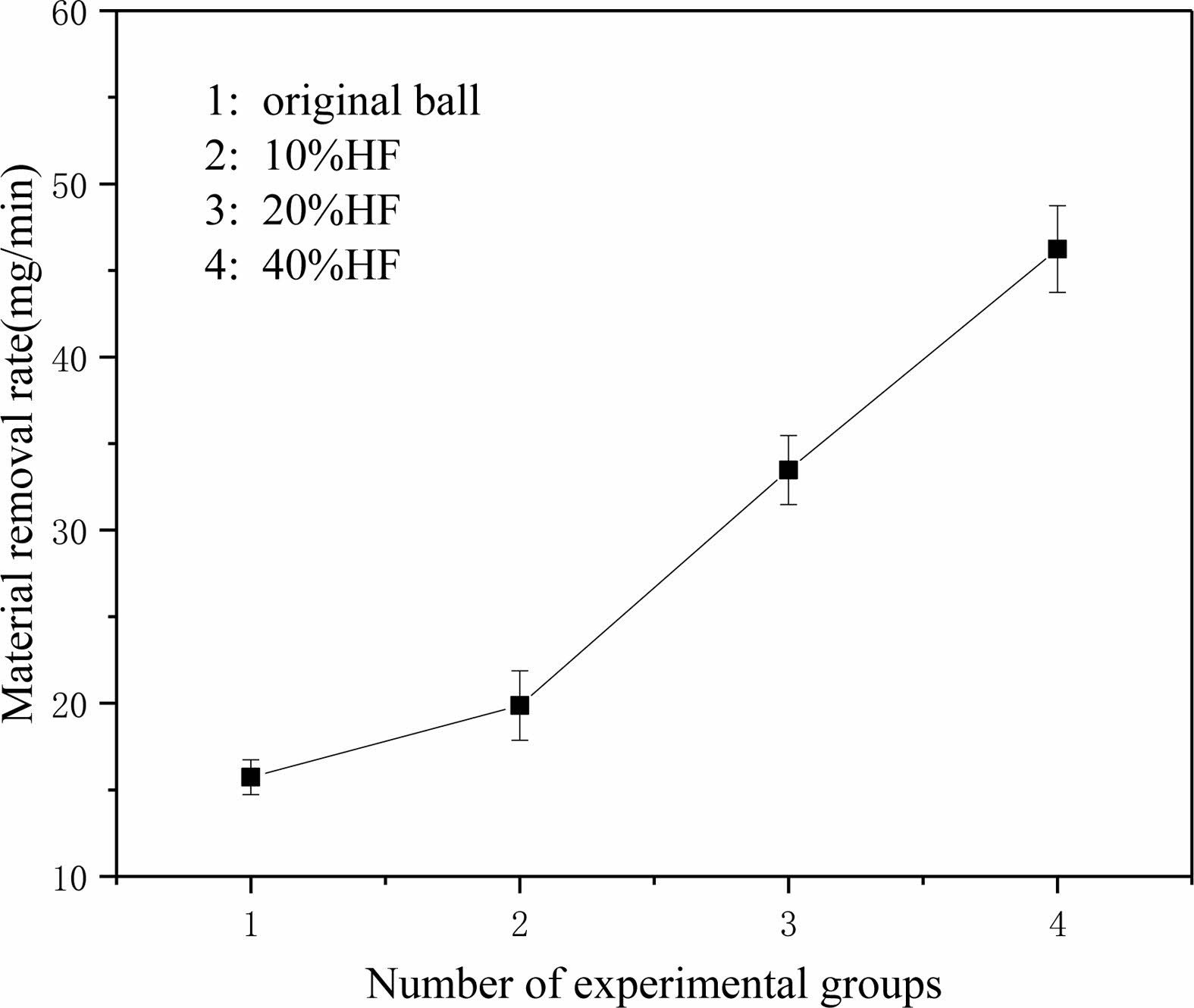
After grinding, balls were placed into anhydrous ethanol for ultrasonic cleaning twice and then weighed with a precision balance after drying. Then, the material removal rate was calculated, and the results are shown in Fig. 8.
Fig. 8 shows that after pretreatment with hydrofluoric acid of different concentrations, the material removal rate of balls increases linearly. The removal rate of balls increases with increasing hydrofluoric acid concentration. There is an insignificant inflection point in the 10% concentration group. It is considered that the corroded layer produced by low-concentration hydrofluoric acid is thin, the corroded layer has been completely removed in the grinding process of less than 3 h, and the uncorroded layer is ground in the remaining time so that the overall removal amount decreases. Under the same process parameters, the material removal rate of original balls is only half of that of balls soaked in 20% hydrofluoric acid and one-third of that of balls soaked in 40% hydrofluoric acid, which means that to achieve the same machining size, original balls require double or more diamond abrasives and time. According to the calculation, if balls are pretreated with 20% hydrofluoric acid before grinding and then processed, the material removal amount is doubled after grinding for three hours, and the processing cost is only 47% of the original. This includes the consumption of abrasive fluid and hydrofluoric acid. The loss of the grinding plate should also be an important factor to consider. Rough grinding focuses on the removal rate, which is related to the abrasive, pressure and rotation speed. However, these will also affect the wear of the grinding plate. Repairing or replacing the grinding plate in the later period greatly increases the cost. Due to the difficulty of processing Si3N4 ceramic balls with large machining allowances, we often consume dozens of hours or even more than one hundred hours of processing time in the rough grinding stage. Hydrofluoric acid pretreatment can greatly reduce the grinding time, which is beneficial for processing. Mass production can adjust the process by batch pretreating balls while grinding other balls that have been corroded, saving the overall processing time.
For the surface layer of corroded silicon-based material, the destruction of the crystal phase and the destruction of the sintering agent will reduce the strength of the material [24]. Although SiO2 formed in Si3N4 is stabilized by the surrounding Si3N4 network [25], fluorine ions can also dissolve SiO2. Even at low concentrations, fluoride ions can make Si3N4 ceramics form a nonstick corroded layer [26-28], which leads to a significant reduction in material strength, making the surface material more susceptible to removal during processing. The specific fracture strength analysis is as follows:
The net interatomic binding force of the Si3N4 ceramic material is 0. When the interatomic spacing changes, it will cause the material to have crack extension as well as a fracture failure critical state. The expression of the net interatomic binding force is:
In the formula, r0 is the interatomic distance when the material is in equilibrium.
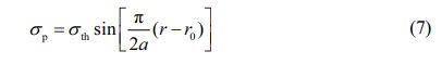
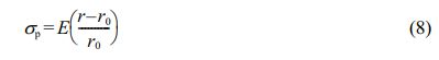
When the atoms are slightly offset, r - r0 is very small, and the stress change of the material satisfies Hooke's law:
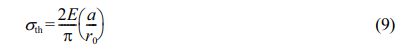
Derivative of the above two formulas with respect to r, the expression of fracture strength (σth) of ceramic materials can be obtained as follows:
Assume that during the fracture process of engineering ceramics, the external force (W) is equal to the energy required by the material to form a new surface:
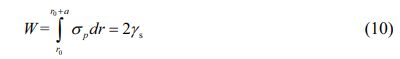
In the formula, γs is the free surface energy of the material.
Obtained:
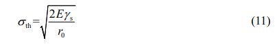
According to Formula (11), the theoretical fracture strength of ceramic materials is mainly affected by the equilibrium distance between atoms in the material structure, the elastic modulus of the material or the free surface energy of the material. For corroded Si3N4, the atomic spacing in the material structure increases with the creation of loose grains. With increasing r0, the appearance of SiO2 in the material leads to a decrease in its atomic packing density, thus reducing the surface free energy and γs. Finally, reducing the fracture strength σth and the difficulty of processing.
Diameter variation
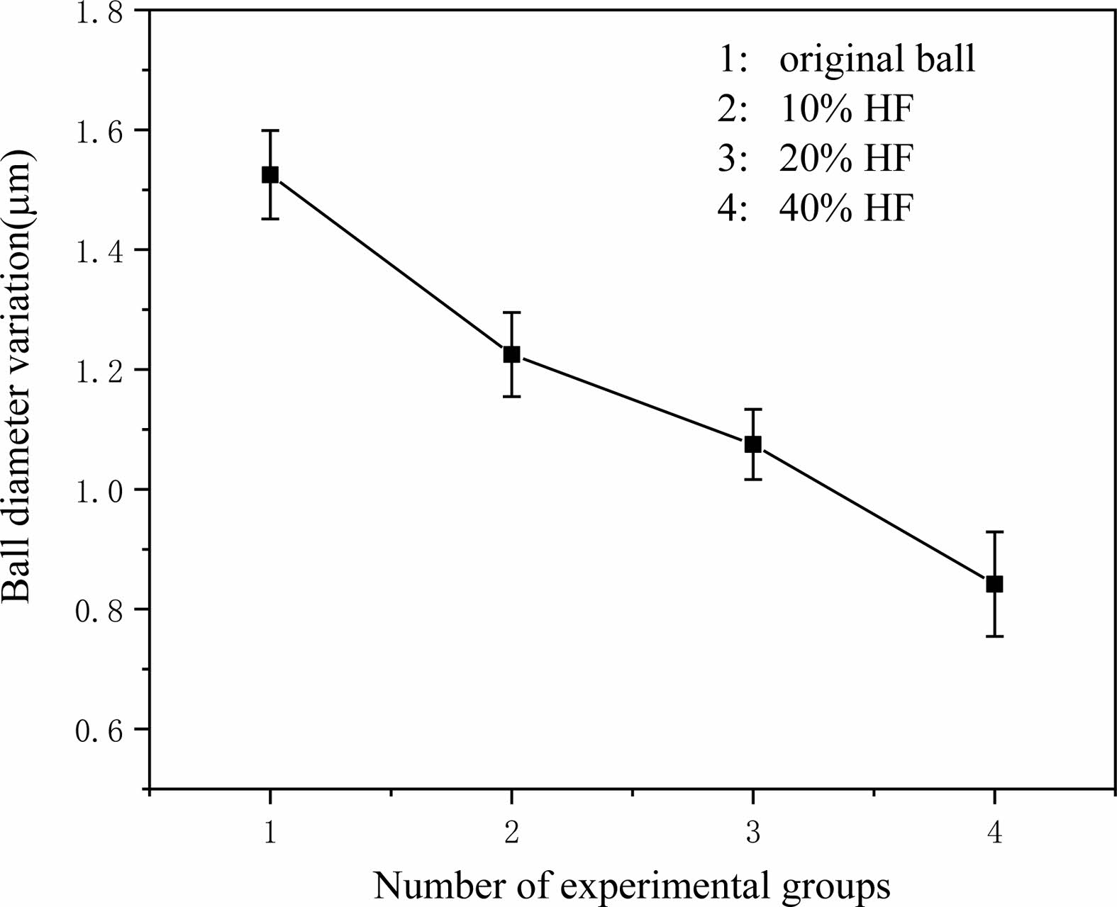
The results of ball diameter variation are shown in Fig. 9. It can be observed that the overall ball diameter variation decreases with increasing concentration of hydrofluoric acid.
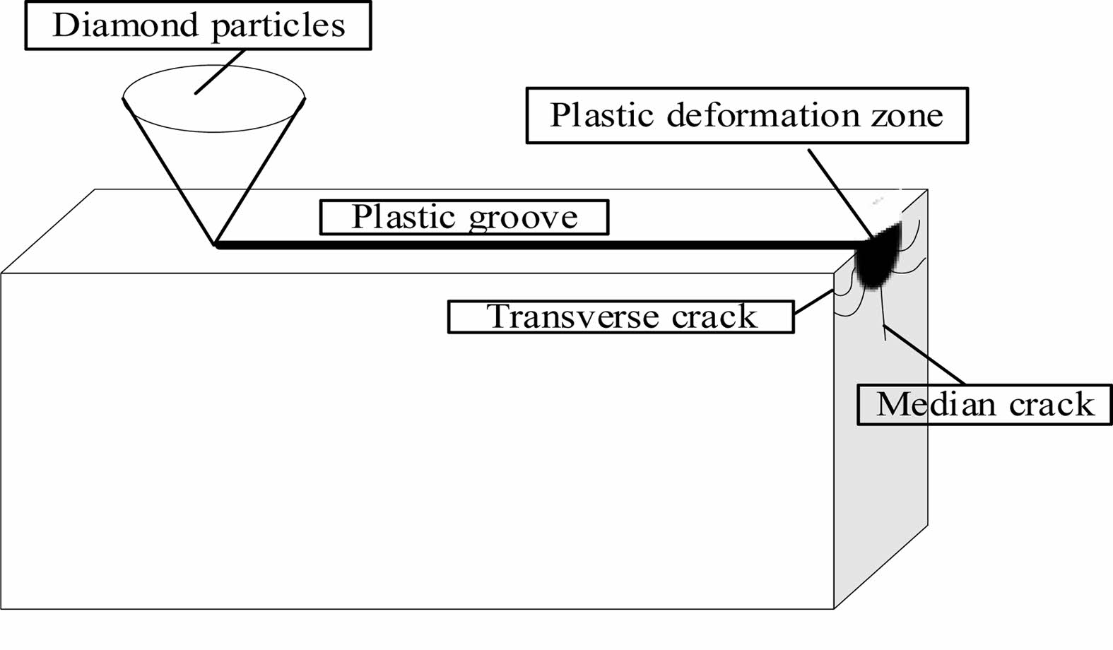
With increasing concentration, the surface strength of the material decreases and is easier to remove, thus improving the precision of Si3N4 ceramic balls. When the abrasive pressure is within a certain range, a plastic deformation zone exists below the indenter, and the corrosive effect of hydrofluoric acid increases the size of the plastic region of the Si3N4 material [29]. As the load increases, two major crack extensions occur in the plastic deformation zone, and when the indenter load exceeds the critical value of the material itself, the crack extensions produces brittle removal, as shown in Fig. 10.
Under the condition of applying the same load, the plastic zone of Si3N4 ceramic balls increases after the pretreatment of Si3N4 ceramic balls by hydrofluoric acid corrosion, the plastic removal increases during rough grinding, the material surface chipping generated by the brittle removal of large particles decreases, and the surface fragmentation rate of Si3N4 ceramic balls decreases, which is conducive to the improvement of the surface quality after the grinding process.
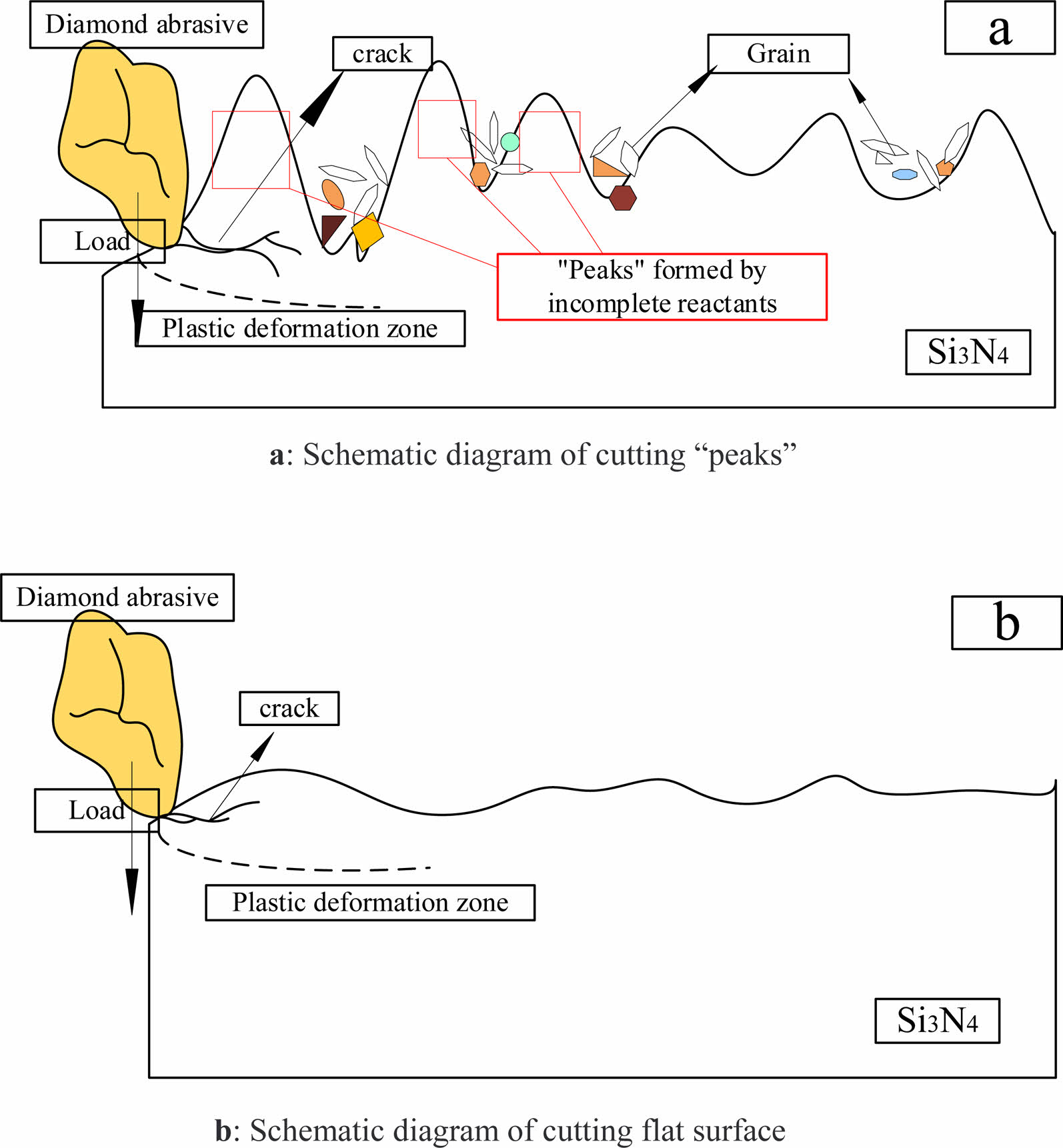
Fig. 11(a) shows the “peaks” of uncorroded Si3N4 surface cutting by diamond abrasive. The fracture strength of the material decreases with increasing reaction time of the Si3N4 material in hydrofluoric acid. Compared with the flat surface of Si3N4 in Fig. 11(b), the removal width of the “peaks” is narrower, and the extension of cracks and fracture of the “peaks” are more likely to occur. It can reduce the processing cost while grinding efficiently.
The removal of the “peak” is not a one-time process; some of the corroded layer remains on the Si3N4 surface after rough grinding, which can be completely removed after sufficient grinding. Different densities of each part of the material will lead to different corrosion rates, but the corrosion rate of hydrofluoric acid for 120 h is almost constant. The difference in corroded depth resulting from different corrosion rates will be much smaller than the error in the shape of the grinding plate, assembly errors, installation accuracy errors and the amount of error in the variation of ball diameter caused by the uneven force on each ball. With the guarantee of the ball-forming mechanism of the device, the ball diameter variation after pretreatment with hydrofluoric acid is reduced to a certain extent, and the reduction of ball diameter variation is more conducive to the subsequent finish grinding.
Surface Morphology after Grinding
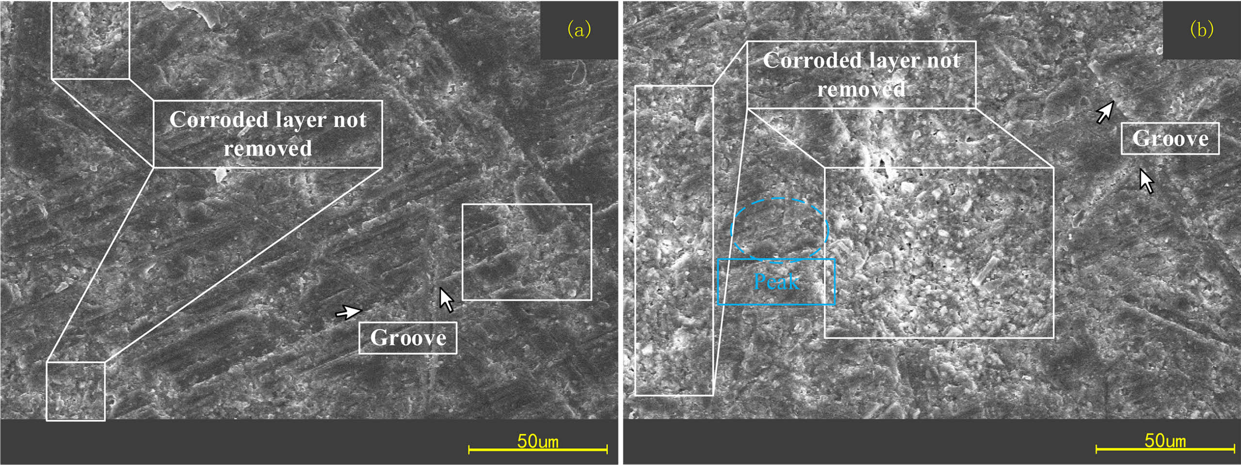
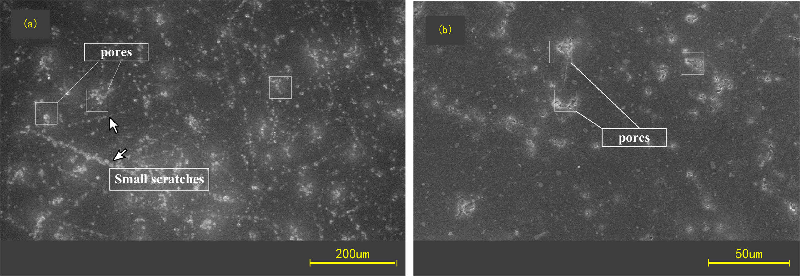
SEM was used to observe the surface of Si3N4 ceramic balls after rough grinding and finish grinding in comparison. The results are shown in Figs. 12 and 13.
It can be observed that there are more obvious scratches or grooves on the surface of Si3N4 ceramic balls after rough grinding, and the corroded layer has not been completely removed, which exhibits fine grains. Because the rough grinding process focuses on the removal rate, the diamond size is larger and the grinding pressure is higher, the surface of Si3N4 ceramic balls after rough grinding shows deeper scratches or grooves. The subsequent processing needs to remove the corroded layer first. No obvious residues of hydrofluoric acid reaction were found on the surface of the finish ground balls and there are few scratches on the surface. The corroded part is basically removed in the finish grinding stage. After sufficient finish grinding, the ball's removed thickness is much greater than that of the corroded layer. Theoretically, the corroded part is completely removed.
Composition analysis
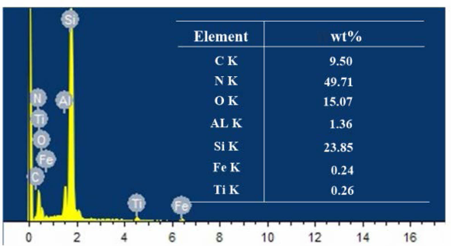
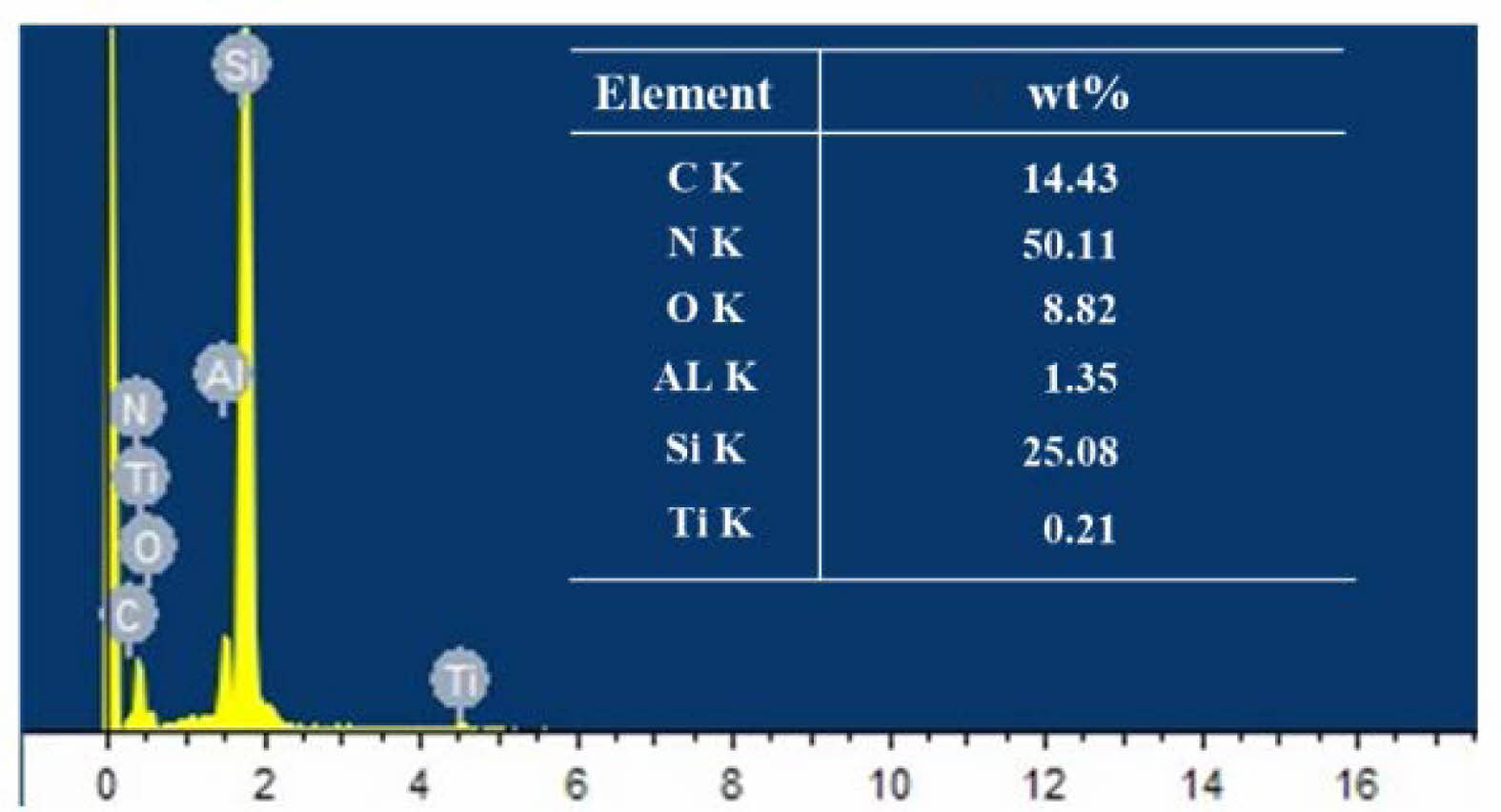
Although no obvious corroded layer residue was observed after finish grinding, to exclude the possible existence of special conditions in the microform, EDS energy spectrum analysis was used to analyze the surface of the original balls as well as the finish grinding balls to clarify whether there was any change in chemical composition, and the results are shown in Figs. 14 and 15. The main elemental components in the energy spectrum are Si and N. The Ti, Al and O elements in the original ball composition are considered to be sintering aids such as alumina, and the C element is considered to be a toughening agent component. Elemental Fe appeared on the surface of the finish ground balls, which is due to the use of cast iron plates for processing ceramic balls, which left some Fe monomers and Fe compounds on the surface of the balls after processing. No F was found, indicating that the hydrofluoric acid reaction residue had been completely removed. Comparing the EDS energy spectrum of the original ball and the fully processed ball after pretreatment with hydrofluoric acid, there is no change in the major elements of the Si3N4 ceramic ball. The content of each other element changed slightly because of the extra coming of iron, but the overall composition of the material remained basically unchanged. Therefore, it can be determined that the hydrofluoric acid corroded layer on the surface of the Si3N4 ceramic balls can be completely removed by sufficient grinding, and the material properties of the Si3N4 material are not affected.
|
Fig. 8 Material removal rate. |
|
Fig. 9 Ball diameter variation. |
|
Fig. 10 Schematic diagram of crack propagation |
|
Fig. 11 Abrasive cutting model (a: Schematic diagram of cutting “peaks”; b: Schematic diagram of cutting flat surface). |
|
Fig. 12 Surface morphology of ceramic balls after rough grinding. |
|
Fig. 13 Surface morphology of ceramic balls after finish grinding. |
|
Fig. 14 EDS spectrum of the ceramic ball surface after finish grinding |
|
Fig. 15 EDS spectrum of original ball surface. |
(1) When hydrofluoric acid reacts with Si3N4 ceramic balls, the thickness of the corroded layer increases with the hydrofluoric acid concentration and reaction time.
(2) Hydrofluoric acid can destroy the surface structure of Si3N4, making it easier to remove the surface material. Under the same grinding processing conditions, the removal rate of rough grinding from the corroded balls is 2-3 times higher than the removal rate of the original balls, and the cost is only approximately half of what it was. It saves processing cost while improving processing efficiency.
(3) Due to the pretreatment effect of hydrofluoric acid, the ball diameter variation of Si3N4 ceramic balls is significantly improved under the same process, which is beneficial to the subsequent process.
(4) After sufficient grinding, the corroded layer can be completely removed, and the material is tested to be unchanged, which will have no effect on the performance of the finished Si3N4 ceramic balls.
This work was supported by the National Natural Science Foundation of China (NSFC) [grant numbers 51975388, 52105196]; Liaoning Provincial Department of Education Project [grant numbers LJKZ0597]; PhD Fund of Liaoning Province of China [grant number 2020-BS-159]; and Young and Middle-aged Innovation Team in Shenyang [grant number RC210343].
- 1. L.T. Wei, Y.H. Yu, and J. Jiao, J. Ceram. Process. Res. 19[2] (2018) 126-129.
- 2. Y. Lu, J.F. Yang, and J.Q. Gao, J. Ceram. Process. Res. 9[6] (2008) 657-660.
- 3. S.H. Ahn and K.W. Nam, J. Ceram. Process. Res. 22[1] (2021) 54-60.
-

- 4. G. Levesque, and N.K. Arakere, Int. J. Solids Struct. 45[25-26] (2008) 6301-6315.
-
- 5. Y.H. Wu, S.H. Li, and K. Zhang, Key Eng. Mater. 291-292 (2005).
-
- 6. T. Kurobe, H. Kakuta, and M. Onoda, J. Jpn. Soc. Precis. Eng. 62[12] (1996) 1773-1777.
-
- 7. B.H. Lv, J.L. Yuan, F. Cheng, and F. Yang, Adv. Mater. Res. doi: 10.4028/www.scientific.net/AMR. 69-70 (2009) 69-73.
-
- 8. N. Umehara, T. Kirtane, R. Gerlick, V.K. Jain, and R. Komanduri, Int. Mach. Tool. Manu. 46[2] (2006) 151-169.
-
- 9. T.H.C. Childs, S. Mahmood, and H.J. Yoon, Tribol. Int. 28[6] (1995) 341-348.
-
- 10. B.H. Lv, J.L. Yuan, Y.X. Yao, and Z.W. Wang, Mater. Sci. Forum. 532 (2006) 460-463.
-
- 11. K.R. Mikeska, S.J. Bennison, and S.L. Grise, J. Am. Ceram. Soc. 83[5] (2000) 1160-1164.
-
- 12. H. Klemm, J. Am. Ceram. Soc. 93[6] (2010) 1501-1522.
-
- 13. M. Herrmann, J. Schilm, W. Hermel, and A. Michaelis, J. Ceram. Soc. Jpn. 114[1335] (2006) 1069-1075.
-
- 14. J. Schilm, M. Herrmann, and G. Michael, J. Eur. Ceram. Soc. 24[8] (2004) 2319-2327.
-
- 15. M. Herrmann, J. Am. Ceram. Soc. 96[10] (2013) 3009-3022.
-
- 16. A.H. Oh, H.S. Lee, B.G. Kim, S.C. Choi, Y.G. Jung, and G.S. An, J. Ceram. Process. Res. 21[4] (2020) 400-406.
-
- 17. S.C. Jeong, S.H. Ahn, and K.W. Nam, J. Ceram. Process. Res. 18[7] (2017) 506-520.
- 18. J.R. Frade and M. Cable, J. Mater. Sci. 32[10] (1997) 2727-2733.
-
- 19. M. Herrmann and J. Schilm, Ceram. Int. 35[2] (2009) 797-802.
-
- 20. R. Conradt, J. Am. Ceram. Soc. 91[3] (2008) 728-735.
-
- 21. G.A.C.M. Spierings and J. van Dijk, J. Mater. Sci. 22[5] (1987) 1869-1874.
-
- 22. J.R. Frade and M. Cable, J. Am. Ceram. Soc. 78[1] (1995) 90-96.
-
- 23. T.A. Michalske and S.W. Freiman, J. Am. Ceram. Soc. 66[4] (1983) 284-288.
-
- 24. M. Herrmann, J. Schilm, G. Michael, J. Meinhardt, and R. Flegler, J. Eur. Ceram. Soc. 23[4] (2003) 585-594.
-
- 25. J. Schilm, M. Herrmann, and G. Michael, J. Eur. Ceram. Soc. 27[12] (2007) 3573-3588.
-
- 26. B. Seipel and K.G. Nickel, Ceram. Int. 30[2] (2004) 267-271.
-
- 27. T. Sato, Y. Tokunaga, T. Endo, M. Shimada, K. Komeya, K. Nishida, and T. Kameda, J. Mater. Sci. 23[10] (1988) 3440-3446.
-
- 28. S.W. Sharkawy and A.M. El-Aslabi, Corros. Sci. 40[7] (1998) 1119-1129.
-
- 29. J.H. Gong, in “Fracture mechanics of ceramics” (Beijing: Tsinghua University Press, 2001).
 This Article
-
2022; 23(5): 685-693
Published on Oct 31, 2022
- 10.36410/jcpr.2022.23.5.685
- Received on Apr 7, 2022
- Revised on Jun 24, 2022
- Accepted on Jun 25, 2022
Services
- Abstract
introduction
hydrofluoric acid corrosion experiment
grinding experiment
conclusions
- Acknowledgements
- References
- Full Text PDF
Shared
Correspondence to
- Songhua Li
-
aSchool of Mechanical Engineering, Shenyang Jianzhu University, Shenyang 110168, China
bNational-Local Joint Engineering Laboratory of NC Machining Equipment and Technology of High-Grade Stone, Shenyang 110168, China
Tel : +86-24-24694319 Fax: +86-24-24694319 - E-mail: lisonghua@sjzu.edu.cn
Clean-Energy Research Institute(CRI), Hanyang University, 222, Wangsimni-ro, Seongdong-gu, Seoul, 04763, Korea
E-mail: jcpr@hanyang.ac.kr