


- Effect of Al2O3/PSZ and Al2O3/YSZ ceramic coating in CI engine fueled with ternary blends of castor seed oil and jatropha oil biodiesel dosed with diesel
P. Mohan Kumara,*, V.C. Uvarajab and P. Madhuc
aDepartment of Mechanical Engineering, Jayalakshmi Institute of Technology, Thoppur, Dharmapuri-636352, Tamil Nadu, India
bDepartment of Mechanical Engineering, Bannari Amman Institute of Technology, Dathyamangalam-638401, Tamil Nadu, India
cDepartment of Mechanical Engineering, Karpagam College of Engineering, Coimbatore-641032, Tamil Nadu, IndiaThis article is an open access article distributed under the terms of the Creative Commons Attribution Non-Commercial License (http://creativecommons.org/licenses/by-nc/4.0) which permits unrestricted non-commercial use, distribution, and reproduction in any medium, provided the original work is properly cited.
In this research work, alumina (Al2O3) with Partially Stabilized Zirconia (PSZ) and Yttria Stabilized Zirconia (YSZ) were coated on the engine piston and intake and exhaust valves using the atmospheric plasma spray technique as a thermal barrier coating (TBC) over NiCrAl bond coat. The aim of this work is to experimentally investigate the thermal cycling behavior and performance and emission analysis of the coated engine fuelled with ternary blends produced from castor and jatropha seed oils dosed with diesel. Three ternary blends were prepared in various proportions of B20, B40 and B50 and tested in coated and uncoated engines. The experimental findings revealed that Al2O3/YSZ based TBC has good thermal cycling behavior and the formation of thermally generated oxide (TGO) was primarily responsible for the spallation of the coating. The ternary blends showed higher brake thermal efficiency (BTE) and lower specific fuel consumption (SFC) when operated in the TBC engine. At B20 operating conditions maximum improvement of 2.98% and 3.43% BTE is recorded using Al2O3/PSZ and Al2O3/YSZ coated engine compared to conventional engine operated with neat diesel. In emissions, compared to conventional diesel engines, both TBC coated engines produced less HC and CO with increased NOx levels
Keywords: Biodiesel, Ternary blends, Thermal barrier coating, Thermal cycle test, Engine performance
The nation's economic status depends on energy resources being accessible and even being successfully transformed. Diesel is the main key source for the rapid growth of the nation’s economy. Due to unique advantages such as higher compression ratio, higher efficiency, and lower fuel consumption, compression ignition (CI) engines are employed in a number of industries, including agriculture, transportation, and power sectors. Based on the statistical analysis, it is clear that demand for energy is growing continuously. But the natural energy resources available are dwindling all over the world at an astounding rate. Therefore, seeking an alternative to this exhausting natural fuel is a must [1]. Emissions from these engines, such as carbon monoxide (CO), unburned hydrocarbons (UHC) and particulate matter (PM) have contaminated the atmosphere. In this pursuit, it is critical to replace conventional polluting fuels with renewable, environ- mentally friendly fuels and to keep the environment clean [2]. Biodiesel the most alternative fuels, used in engine directly or mixed with diesel to reduce exhaust pollutant emissions [3].
Many studies have reported the results conducted on IC engines with different types of biodiesel and have achieved better performance with a greater reduction in engine emissions. Aransiola et al. [4] prepared neem biodiesel using a transesterification process and utilized it for diesel engines. The study showed lower emissions of CO and NO than pure diesel. Preparation and utilization of ternary blends for diesel engines have attracted attention in recent years due to improved efficiency and decreased emissions [5]. Thakkar et al. [6] conducted combustion modelling using ternary blends of biodiesel/n-butanol/diesel on IC engines. The study reported a significant reduction in all engine emissions. Kumar et al. [7] reported that the ternary blends of pongamia and waste cooking biodiesel with diesel showed equal BTE compared to diesel. The engine emissions such as HC and CO are also reduced with the use of ternary blends compared to neat diesel. Ternary blends of linseed, rubber seed and diesel blends in IC engines were prepared and utilized as a fuel for IC engines by Sudalaiyandi et al. [8]. The study utilized 10%, 20% and 25% of each biodiesel to make three different blends of B20, B40 and B50. The study showed increased BTE with reduced SFC for biodiesel blends. The use of ternary blends also showed reduced NO2 and CO emissions compared to conventional diesel fuel. Raguraman et al. [9] have taken various tests on IC engines using different blends of pyrolysis oil with diesel fuel. The study utilized pyrolytic oil derived from thermocol wastes and pressed oil cake. The study suggested 10% blend of pyrolysis oil for IC engine fuel to get equal performance as diesel fuel. At higher loads the engine shows equal performance with reduced emissions compared to diesel fuel at 10% blend. Biodiesel with alcohol content could be a suitable replacement for IC engine operations. Goga et al. [10] tested an IC engine fuelled with rice bran oil biodiesel and n-butanol. The study showed improved performance with reduced hazardous exhaust emissions. Fagundez et al. [11] investigated the engine operating characteristics with a mixture of n-butanol/ethanol as fuel in an engine. The result showed worse performance than ethanol due to lower octane number. Without any modification to the diesel engine, triglycerides give good engine performance as a better alternative fuel [12]. The lower volume proposition of rapeseed oil blended with diesel fuel without any engine modification shows higher smoke, CO and HC emissions than diesel under all loads. But in a higher blend proposition, all emissions seem lower than diesel. However, NOx emission becomes worse simultaneously [13].
Thermal Barrier Coating in engine components has drawn great attention for the past two decades due to its intense properties like reduced emissions, stresses and corrosion [14]. TBCs generally consist of two-part systems that include a base bond coat and a top ceramic coat. Al2O3, SiO2, MCrAlY alloys, and many other materials were commonly used for the bond coat. Among these materials, Al2O3 is popular and has been utilized for many studies due to its low oxygen diffusivity and greater resistance to corrosion [15, 16]. It is also used for many engineering applications and is known as high-temperature ceramics [17]. YSZ, mullite, alumina, PSZ, CeO2, La2Zr2O7, silicates, spinel, are the commonly applied ceramic coatings of engine components. Kim [18] conducted a survey on the application of Al2TiO5 ceramics for the reduction of PM from diesel engines. The low thermal expansion and low Young’s modulus of the Al2TiO5 make it well suitable for coating in the engine particulate filter. Mohamed Musthafa et al. [19] conducted experiments on engine performance coated with 200 µm fly ash. The study showed increased BTE with reduced SFC. In this study, the emission of smoke was also reduced. The study conducted by Jianguozhu [20] use of 8% PSZ on Ni substrate improved the Young’s modulus and hardness of the base material. Utilization of PSZ on a four stroke diesel engine showed 7.5 ppm reduction in HC emissions, 0.04% reduction in CO emissions. However, NOx emissions increased by up to 10 ppm. The use of CaZrO3 coating on the cylinder head, valves and piston crown of the six cylinder water cooled engine shows the reduction on BSFC upto 285 g/KW-h with 38% increased efficiency [21]. On a single cylinder CI engine, Praveen Raman [22] employed YSZ as a TBC material with algal oil biodiesel and found increment in heat release rate and in-cylinder pressure of 13% and 20% respectively. Hejwowski and Weronski [23] used Al2O3 +40% TiO2, ZrO2+8% Y2O3, Al2O3+40% ZrO2 with different coating thickness of 3500, 3000 and 2500 µm. The study reported that the reduction of 21.4% in SFC.
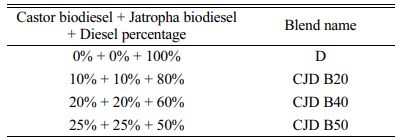
Based on the collected literatures, it is observed that there was inadequate research work on the use of ternary blend in TBC engine. This study focused on preparing ternary biodiesel blends of jatropha (J) and castor (C) biodiesels with pure diesel (D) to analyze the engine operating characteristics of 50%Al2O3-50%PSZ (TBC1) and 50%Al2O3-50%YSZ (TBC2) coated engines. The fuel blends used in these studies were made by varying the percentages of jatropha and castor oil biodiesel in the fuel. Blended samples (CJD) are B20-(80 10 10), B40-(60 20 20) and B50-(50 25 25) respectively.
Test fuel
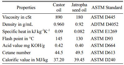
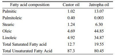
Ricinus communis (castor seed) and jatropha seed oil used for this study were obtained from the cold press method. The collected oil is then converted into biodiesel through a transesterification process. Prior to the conversion, the oil was tested for its physical characterization and fatty acid composition. The physical characteristics and fatty acid profile of the oils are given in the Table 1 and 2. Here, the physical analysis of the castor and jatropha seed oils was performed by following the ASTM standards mentioned in the Table 1.
Preparation of biodiesel
Due to lower acid value of the selected vegetable oils, base catalyzed transesterification procedure was opted for this study. Initially 0.1 N of dilute KOH solution is prepared by dissolving 4 grams of KOH in 1 litre of water. The castor seed oil is next blended with methanol (CH3OH) and diluted with 0.1 N KOH in the desired ratio. In the next step, 400 ml of raw castor seed oil with 100 ml of methanol and 9 ml of dilute 0.1 N potassium hydroxide solutions were mixed well. The mixture is heated then to 60 ºC and kept for 90 minutes. After heating the prepared oil mixture, it was allowed to quench for 1440 minutes. Glycerin formed during the biodiesel production process is obtained at the bottom and removed. At the end, the electronic weighing machine is used to calculate the biodiesel produced as a balance from the solution. The same process is repeated to produce biodiesel from jatropha seed oil.
Preparation of ternary blends
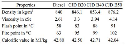
Castor and jatropha oils have higher fatty acid contents. The selected jatropha oil has a low viscosity, cheap and available in plenty when compared to castor oil. Blending these biodiesels with diesel provides a noble economic feasibility. In this study, the prepared ternary biodiesel blends shown in the table were prepared and utilized for engine analysis. All prepared fuels were tested in the engine at different loading conditions of 0%, 25%, 50%, 75% and 100%. Table 3 shows the prepared ternary blends and Table 4 shows their properties.
Preparation of coatings
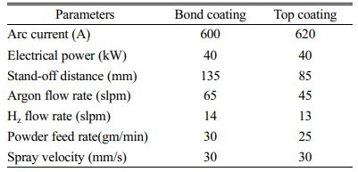
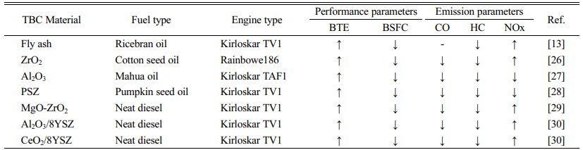
TBC is a ceramic coating that is generally processed by the atmospheric plasma spray (APS) technique. This is a convenient method for coating the cylinder head, piston crown and valves [24]. For this, the surface of the substrate is cleaned by acetone. To improve the bond strength, a grit-blasting process is done over the surfaces for 6 μm [25]. In this study, 100 μm NiCrAl is used as the bond coating material and 200 μm of 50%Al2O3-50%PSZ and 50%Al2O3-50%YSZ are coated over NiCrAl. The overall thickness of TBC is maintained at 300 μm. Table 5 shows operating procedures applied to APS processes. In order to maintain the same compression ratio mentioned in the standard diesel engine, a micro machining process was carried out prior to the coating. Table 6 shows some recent studies related to TBC engines operated with diesel and biodiesel.
Thermal cycling test
A Thermal cycling test is executed in an incinerator. In this experiment, the sample is heated in an incinerator and then quenched in a cold environment. In this study, the coated specimen was taken for a thermal cycling test with dimensions of length 15 mm, width 10 mm and thickness 5 mm. The samples are heated to 800 °C and maintained for about 5 minutes. After that, the specimen is quenched to room temperature by dipping in water maintained at 25 °C. In this study, the tests were performed after 60 cycles. During experimentation, the samples are inspected carefully to check spallation every 15 cycles.
Experimental setup and procedure
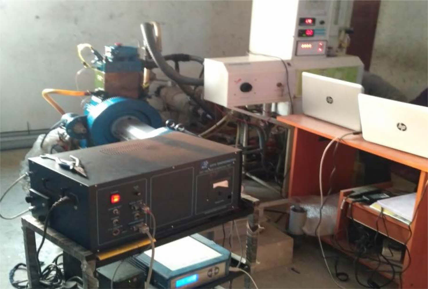
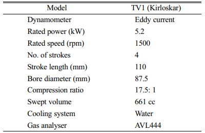
The overall experimental set up is shown in Fig. 1 and the technical specifications of the test engine are listed in Table 7. The engine is attached to a dynamometer, which works based on eddy-current theory. The dynamometer is calibrated every time before use. The engine is started manually and operated with neat diesel until it reaches a steady state condition. Before conducting the experiment, the engine was thoroughly checked to ensure that there were no fuel and lubricant leaks. When the coolant water reached 50 °C the engine was ensured reaching steady state. Totally the readings were taken in three different phases. In the first phase, the engine was operated with neat diesel and its ternary blends on an uncoated engine. The values such as fuel consumption, exhaust temperatures were measured at increased load conditions. The tests were conducted by changing its load from 0 to 100% at 25% load interval. In each test, the fuel consumption, smoke, concentrations of CO, HC and NOx emissions were measured at constant speed. An AVL type multi-gas analyzer was used to find the exhaust gas concentrations. In the second and third phases, the TBC coated pistons were fixed and the experiments were repeated.
|
Fig. 1 Experimental setup |
Thermal cycling behavior
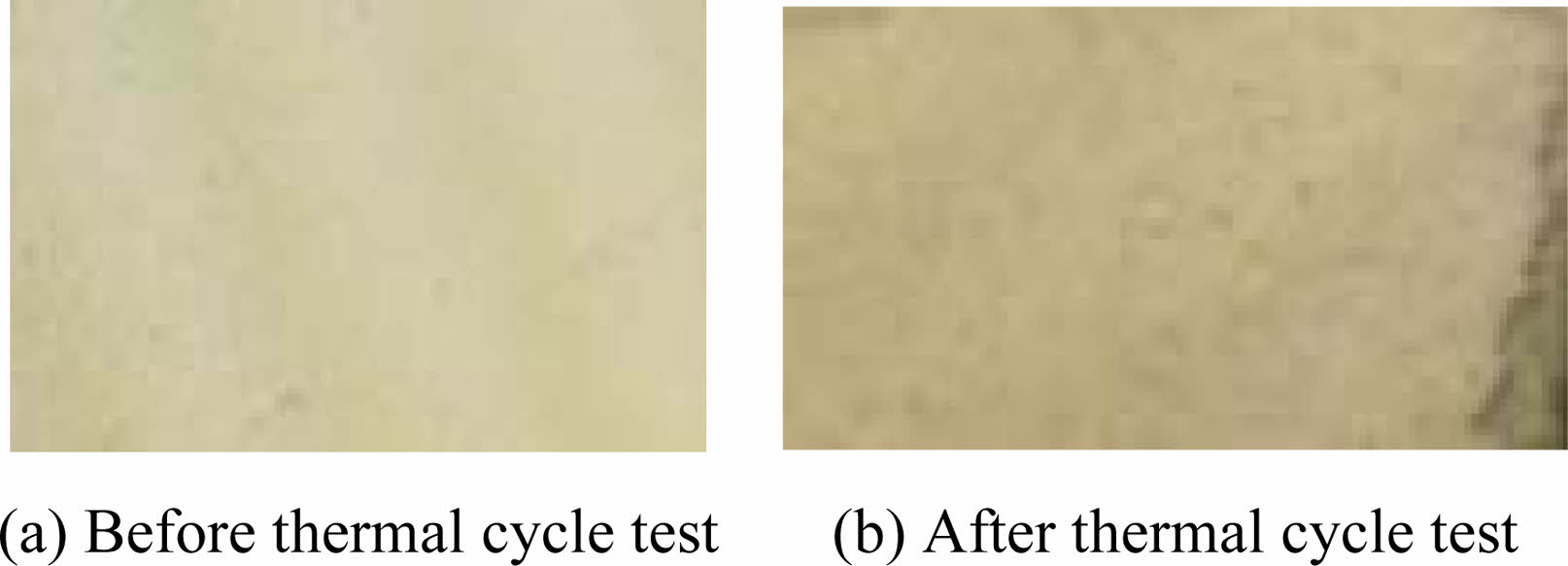
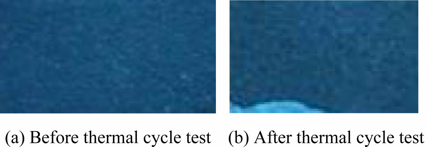
The cyclic oxidation kinetics of two plasma sprayed coated materials were investigated using a cyclic oxidation test. These tests are performed to find the lifetime of coating at 1000 °C. Generally, a typical coating experiences spallation at the corners. The microscopic images of TBC1 and TBC2 coated materials after the tests are shown in Figs. 2 and 3. In this test, no spallation was found in the edges of two coated materials after 100 cycles. However, after 100 cycles, spallation occurred at the corners. For TBC1 material, the spallation occurred after 120 cycles and for TBC2 material, it started after 135 cycles. According to the observations made during this test on the coated sample, spallation started at the corner and subsequently spread to the nearby areas. The thermal stress at the edges of the coated material due to rapid heating and sudden cooling resulted in spallation [31]. The life of the coating can be further improved by a nanostructured coating that offers better thermal cyclic oxidation resistance [32]. The spallation in the material occurred due to thermally grown oxide and the coefficient of thermal expansion between the bond coat and the top coat. It has also been experimentally investigated in many studies [33, 34].
Microstructure analysis
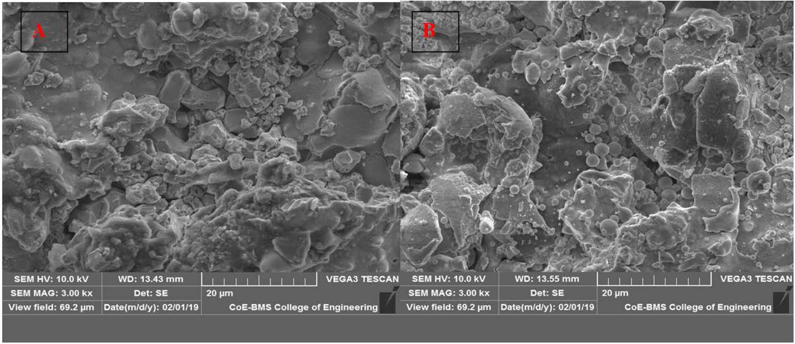
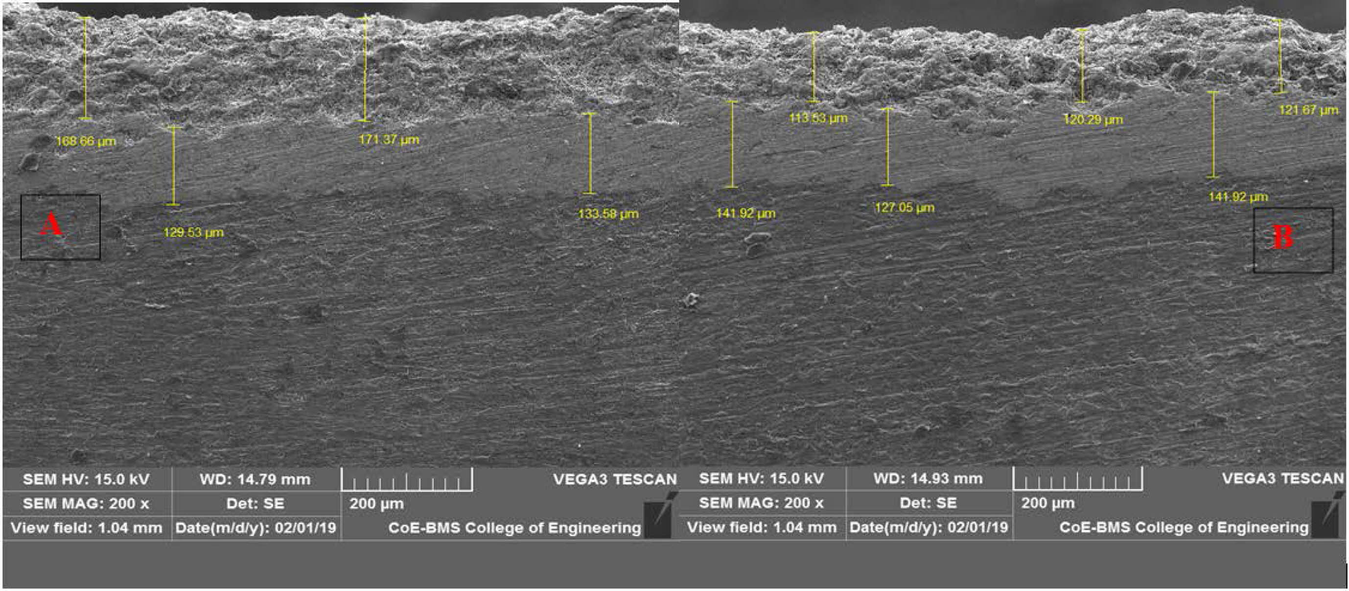
The SEM photographs of the two TBCs are shown in Fig. 4. From the figures, it can be understood that both coatings exhibit a rough surface along with micro cracks. Some of the open voids are also identified by SEM analysis. The rough surface is caused by partially melted rough ceramic powders and mismatched particles during the plasma spraying process. Furthermore, as seen in SEM images, the surface of TBC1 and TBC2 has extremely few pores. The difference in co efficient of thermal expansion between coating material and ceramic powder may be another factor for the presence of micro cracks [35]. The cross section micrograph of TBC1 and TBC2 is depicted in Fig. 5. It can be understood from the cross sectional image that, TGO scale are formed in between two coats. In both coatings, some transverse cracks appear around the interface of the ceramic layer and TGO. These kind of cross lined cracks in the coating are the hitches to thermal shock performance [36]. The formation of the TBC2 coating over NiCrAl has more micro level pores than the TBC1 coating over NiCrAl. The transverse cracks between the bond and ceramic coat of TBC2 make provisions for maximum thermal cycling life time compared to TBC1.
Engine analysis
Brake thermal efficiency
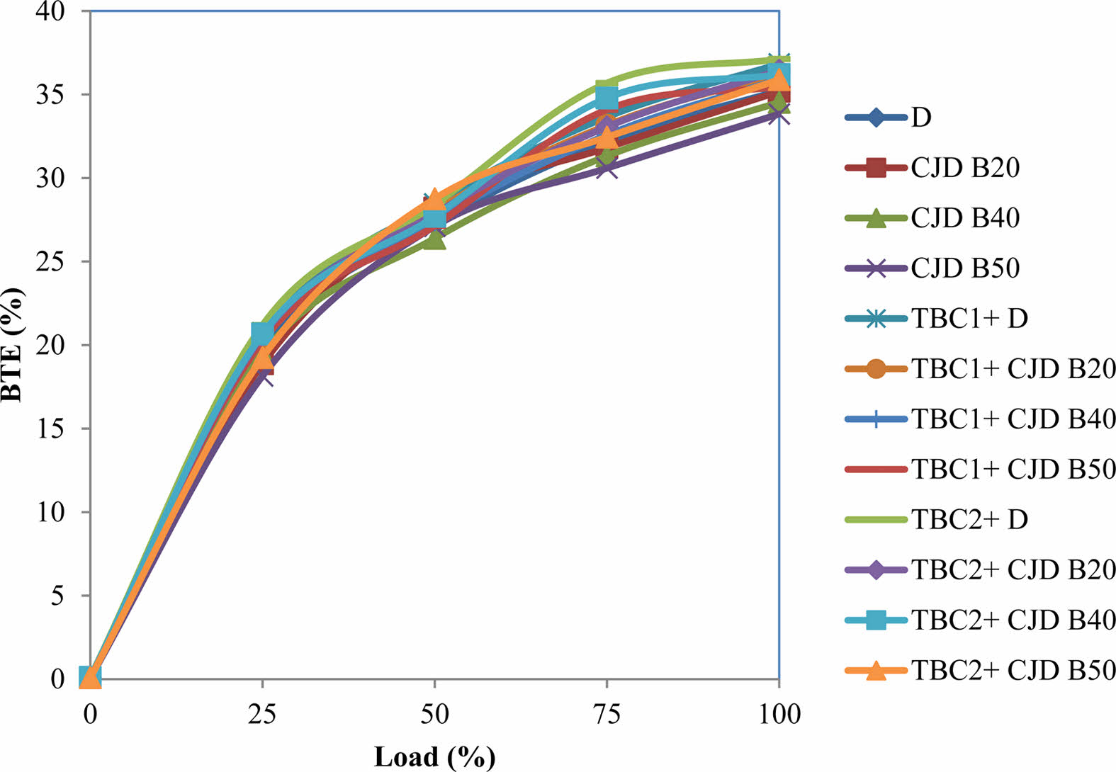
The values of BTE of the ternary blends with coated and uncoated engines are illustrated in Fig. 6. The BTE of the ternary blend fuel and pure diesel at maximum load is 35.23%, 35.18%, 34.53%, 33.83%, 36.83%, 36.28%, 35.91%, 35.468%, 37.12%, 36.449%, 36.19% and 35.88% for neat diesel, CJD B20, CJD B40, CJD B50, TBC1+D, TBC1+CJD B20, TBC1+ CJD B40, TBC1+CJD B50, TBC2+D, TBC2+CJD B20, TBC2+CJD B40 and TBC2+CJD B50 respectively. The maximum BTE value was recorded for pure diesel operated with a TBC2 coated engine, while the minimum BTE value was recorded for 50% blended fuel operated with a conventional engine. At all loads, the TBC coated engines have higher BTE than conventional engines. Comparing to diesel operated in conventional engine, the maximum improvement of 2.92% and 3.38% BTE is recorded with 20% blend operated in TBC1 and TBC2 engine respectively. The increase in BTE is generally aided by the reduction in fuel consumption for delivering equal output power. The coating layer in the piston and valves has the effect of causing a high pressure ratio [29]. The slight increase in pressure ratio improved the braking power of the engine. In agreement with Das et al. [37] the increment in BTE of a coated engine with respect to increased load is due to an improved pre-thermal reaction, which progresses the flame velocity and leads to complete combustion. When the load is increased, more fuel is supplied and more heat is produced. The coating in the piston preserves the generated heat and converts it into useful work, which increases the brake power. The BTE of the engine operated with biodiesel is very low. In particular, the engine operated with CJD B40 and CJD B50 showed very lower BTE of 34.53% and 33.83%, respectively. The decreased BTE is due to lower calorific value and higher fuel consumption compared to other blended fuels [38].
Brake specific fuel consumption
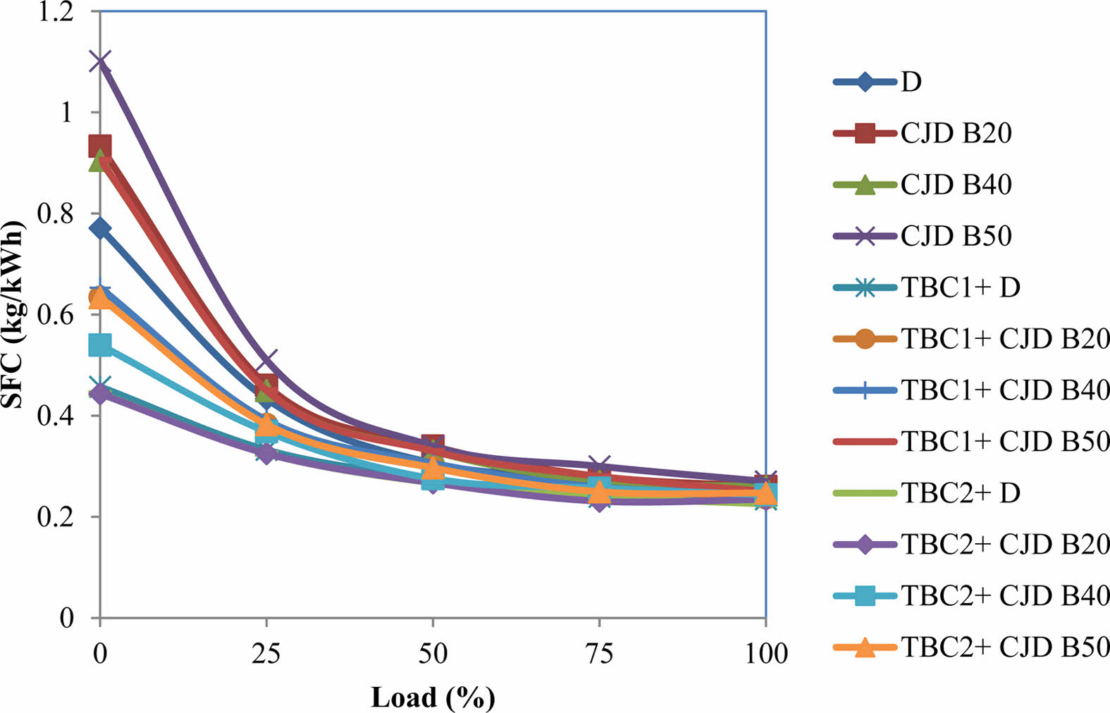
In coated engines, more pressure is applied on the surface of the piston due to increased combustion temperature [39]. This means that the same amount of fuel can generate the same power in TBC engines. Fig. 7 demonstrates that the value of SFC linearly decreases with increased loads. The SFC values of the ternary blends with coated engines are lower than diesel at 100% load. The BSFC for neat diesel, CJD B20, CJD B40, CJD B50, TBC1+D, TBC1+CJD B20, TBC1+ CJD B40, TBC1+CJD B50, TBC2+D, TBC2+ CJD B20, TBC2+CJD B40 and TBC2+CJD B50 are 0.256 kg/kWh, 0.26 kg/kWh, 0.26 kg/kWh, 0.27 kg/kWh, 0.234 kg/kWh, 0.237 kg/kWh, 0.247 kg/kWh, 0.25kg/kWh, 0.225 kg/kWh, 0.234 kg/kWh, 0.243 kg/kWh and 0.247 kg/kWh respectively. When diesel is operated in a standard engine, the value of BSFC is decreased by up to 8.59% and 12.11% in TBC1 and TBC2 engines. Compared with conventional engine, the maximum reduction of BSFC was recorded with a 20% blend of ternary fuel, which shows 7.42% and 8.59% of reduction when operated in TBC1 and TBC2 engines. The higher air turbulence pushed into the chamberassisted to form a homogenous mixture within the engine cylinder as the load increased. This resulted in higher combustion efficiency and lower fuel usage. Due to increased cylinder gas temperatures in TBC engines, the ignition delay time was decreased, which improved the combustion efficiency [40].
Emission analysis
CO emission
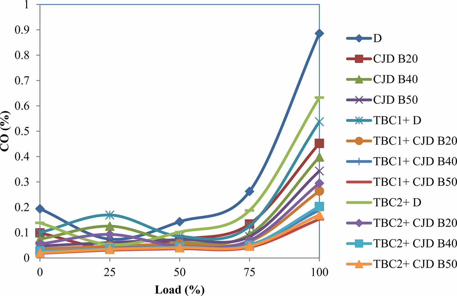
Fig. 8 shows CO emissions with respect to applied load for all twelve operating conditions. From the figure it is clearly identified that CO percentage emissions increase for increased loads. The formation of CO at lower load for all cases is slightly the same, but the emission increases as load increases rapidly. The maximum CO production is observed with neat diesel operated in a conventional engine. The formation of CO is reduced when biodiesel is used. At the same time, when compared to conventional engines, the CO emissions decreased for all fuel blends operated in coated engines. Generally, incomplete combustion generates more CO [41]. The complete combustion due to adequate oxidants in the 50% ternary fuel produces lower CO than neat diesel and lower blends in all engines. At 100% load, neat diesel produces 0.885% of CO emissions whereas TBC1+CJD B50 produces lower level of 0.153% CO. Almost 82.7% of CO emissions were reduced by 50% ternary blend fuel used in the TBC1 coated engine. The abridged pre-mixed combustion in the coated engines reduced CO formation at the initial stage and the higher cylinder temperature during diffusion combustion speed up the oxidation of CO [37]. From the experimental results, as compared to conventional engines operated with neat diesel, CJD B20, CJD B40, CJD B50 fuels, TBC1 engine emits 39.32%, 41.81%, 52.51% and 55.39% lower CO and the TBC2 engine emits 28.59%, 34.73%, 48.99% and 50.44% lower CO.
HC Emissions
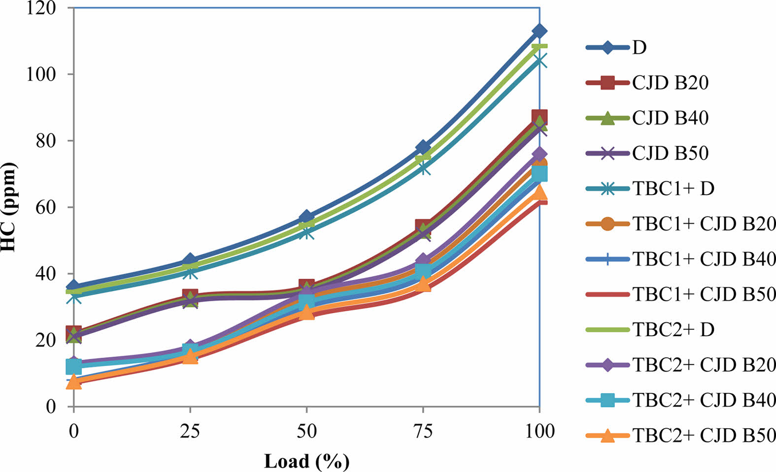
The emission of HC in ternary fuel and neat diesel operated in the engines is depicted in Fig. 9. The readings were taken with increased engine loads. From the experimental results, it can be understood that at 100% load conditions, a considerable reduction in HC emissions was recorded for all tested fuels operated in TBC engines. Comparing to conventional engine, CJD B20, CJD B40, CJD B50 fuels TBC1 engine emits 7.84%, 16.14%, 20.24% and 26.55% lower HC and TBC2 engine emits 4.0%, 12.64%, 17.85% and 22.68% lower HC. The lower emission of HC for biodiesel in coated engines may be due to increased combustion temperature caused by lower heat rejection to the exhaust systems [19]. It is also attributable to a reduction in heat losses to the engine cooling water and an increase in the after-combustion temperature [42]. The results clearly show that the ceramic coating on the engine enhances the combustion characteristics of the engine, including mixture ratio and oxygen amount. At higher loads, the differences in HC emissions are observable. But at lower loads, the changes are not ample. The supply of fuel and net heat produced inside the cylinder is low, which is not enough to achieve complete combustion.
NOx emissions
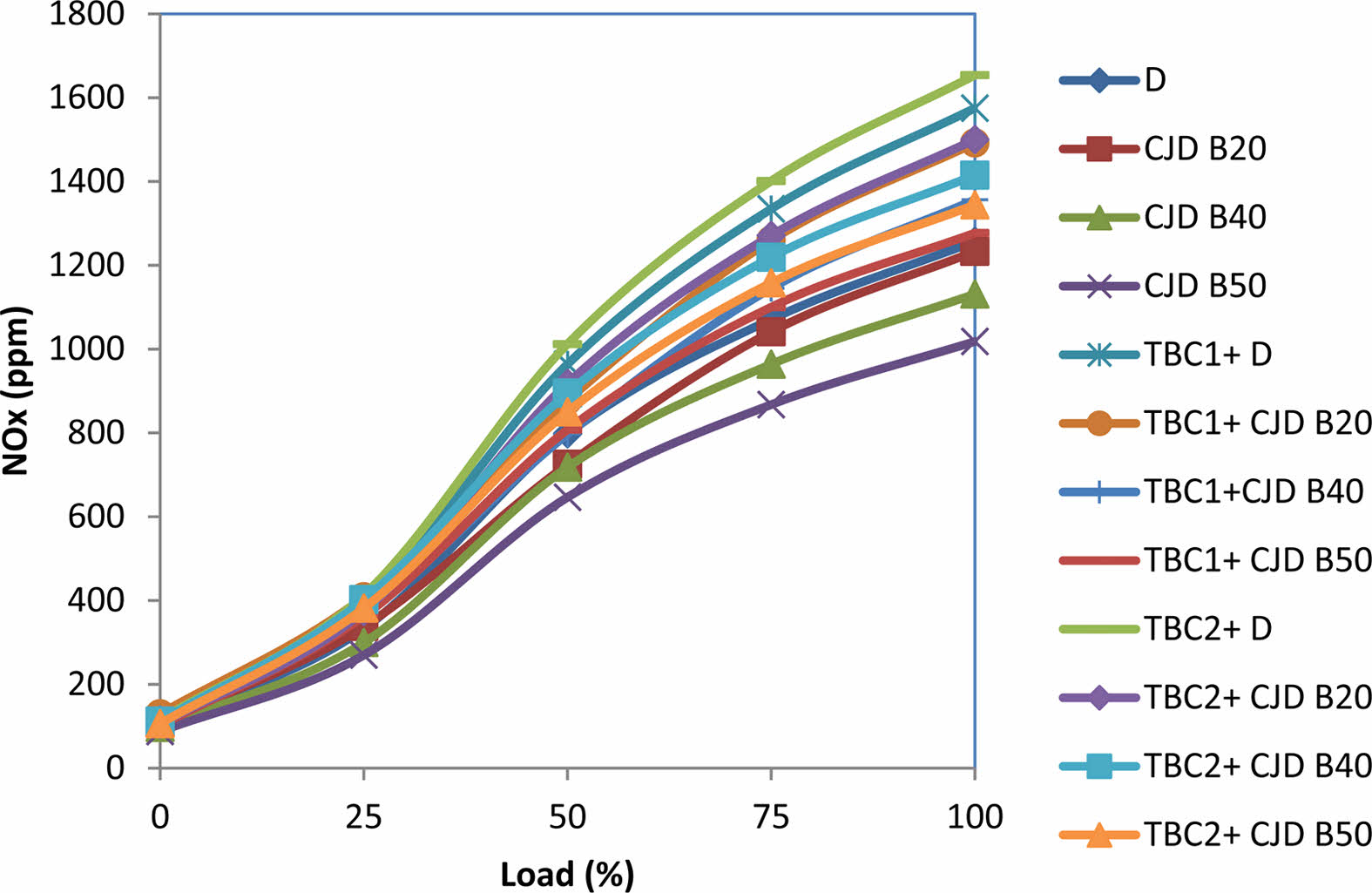
The effect of NOx concentration on coated and non-coated engines operated with different tested fuels is depicted in Fig. 10. Initially, lower NOx emissions are observed for all engines, though at higher loads, the engine emits maximum NOx. When diesel is used as a working fuel, the increase of NOx is 25.3% and 31.56% for TBC1 and TBC2 engines respectively compared to conventional engines. The main reason for the increased NOx production is the higher combustion chamber temperature [8]. Consistent with the Zeldovich mechanism, during combustion, the OH radicals are produced and react with nitrogen atoms to formulate further NOx [43]. At 100% load, the value of NOx for neat diesel, CJD B20, CJD B40, CJD B50, TBC1+D, TBC1+CJD B20, TBC1+CJD B40, TBC1+CJD B50, TBC2+D, TBC2+CJD B20, TBC2+CJD B40 and TBC2+CJD B50 are 1257 ppm, 1233 ppm, 1131.3 ppm, 1018.17 ppm, 1575 ppm, 1491.93 ppm, 1356.3 ppm, 1277.03 ppm, 1653.75 ppm, 1500 ppm, 1415 ppm and 1344.25 ppm respectively. These results are also consistent with previous research findings [44, 45]. More than 90% of NOx produced in a conventional engine comes as NO, with the remaining 10% consisting of NO2, NO3 and NO4. When coated engines are used, the formation of NO is reduced by 60%. In general, it can be concluded that, in TBC engines, the percentage of harmful NO was lowered with increased NOx level.
|
Fig. 2 Macroscopic view of TBC-1 sample. |
|
Fig. 3 Macroscopic view of TBC-2 sample. |
|
Fig. 4 Surfacemorphologies of top surface (a) TBC1 (b) TBC2. |
|
Fig. 5 Cross sectional morphologies of TBC (a) TBC1 (b) TBC2 |
|
Fig. 6 Brake thermal efficiency for various blends. |
|
Fig. 7 Specific fuel consumption for various blends. |
|
Fig. 8 Emission of CO for various loads. |
|
Fig. 9 Emission of HC for various loads. |
|
Fig. 10 Emission of NOx for different loads. |
The current research focused on finding the impact of thermal barrier coating on CI engine fuelled with ternary blends of castor oil and jatropha oil biodiesel dosed with diesel. The tests were performed on conventional engines as well as Partially Stabilized Zirconia and Yttria Stabilized Zirconia coated diesel engine. 50%Al2O3-50%PSZ and 50%Al2O3-50%YSZ TBC coatings are made by the atmospheric plasma spraying technique. Before conducting the performance and emission analysis on the engines, a thermal cycle test was conducted on the coated samples. The following are the key findings of the current research:
· The thermal cycling performance of TBC2 coating demonstrated increased coating life by reducing TGO, resulting in lower stress at the intermediate layer
· The spallation at coating was caused by increased residual stress in the intermediate layer. The expansion of TGO and phase transition are the causes of increased strains
· At 100% load conditions, BTE for all blends in both coated engines shows higher than conventional engine operated with diesel fuel
· When compared to conventional engines operated with neat diesel, TBC1 and TBC2 coated engines had a maximum improvement of 2.98% and 3.43% BTE at B20 operating circumstances
· The results also showed a decreased value of SFC in the TBC engine due to lower thermal conductivity. For all tested fuel, the coated engine showed lower consumption than the conventional engine. Compared to conventional engines operated with neat diesel, TBC1 coated engines had a maximum decrement of 7.41% while operating with CJD B20
· The heat transmission in both the coated engines was seen to be reduced, and as a result, the performance and emission characteristics of the engine were positively affected
· Due to coating in engine components, the emission characteristics are decreased in CO, HC with a slight increment in NOx concentration. Compared to conventional engines operated with neat diesel, TBC1 and TBC2 engine operated with CJD B50 shows lower CO emissions of 82.72% and 80.8%. Similarly HC emissions were reduced by 45.69% and 42.83% respectively
· The increased NOx emissions on coated engines are attributed to the increment in exhaust gas temperature
According to the findings, the B20 and B40 ternary blend biodiesel could be a hopeful alternative to conventional diesel in PSZ and YSZ coated engines, providing improved performance and lower emissions.
IC : Internal Combustion
CI : Compression Ignition
TBC : Thermal barrier coating
APS : Atmospheric plasma spray
BTE : Brake Thermal Efficiency
Al2O3 : Aluminium oxide
PSZ : Partially stabilized zirconia
YSZ : Yttria stabilized zirconia
BSFC : Brake Specific Fuel Consumption
KOH : Potassium hydroxide
TGO : Thermally grown oxide
SEM : Scanning electron microscope
CO : Carbon monoxide
HC : Hydrocarbon
NOx : Oxides of nitrogen
PM : Particulate matter
- 1. C. Vibhakar, R.S. Sabeenian, S. Kaliappan, P.Y. Patil, P.P. Patil, P. Madhu, C. Sowmya Dhanalakshmi, and H.A. Birhanu, Adv. Mater. Sci. Eng. 2022 (2022) 8175552 .
-

- 2. X. Li, J. Ceram. Process. Res. 23[1] (2022) 53-56.
-
- 3. A.S. Kumar, S. Yuvaraj, and S. Janaki, J. Ceram. Process. Res. 21[2] (2020) 217-225.
-
- 4. E.F. Aransiola, E. Betiku, D.I.O. Ikhuomoregbe, and T.V. Ojumu, Afr. J. Biotechnol. 11[22] (2012) 6178-6186.
-
- 5. M.G.R.M. Mofijur, A.M. Rasul, J. Hyde, A.K. Azad, R. Mamat, and M.M.K. Bhuiya, Renew. Sustain. Energy Rev. 53 (2016) 265-278.
-
- 6. K. Thakkar, S.S. Kachhwaha, P. Kodgire, and S. Srinivasan, Renew. Sustain. Energy Rev. 137 (2021) 110468.
-
- 7. P. Kumar, M.P. Sharma, and G. Dwivedi, Egypt. J. Pet. 25[2] (2016) 255-261.
-
- 8. K. Sudalaiyandi, K. Alagar, M.P. VJ, and P. Madhu, Fuel 285 (2021) 119255.
-
- 9. D. Raguraman, A. Kumar, S. Prasanna Raj Yadav, P.Y. Patil, J. Samson Isaac, C. Sowmya Dhanalakshmi, P. Madhu, and J. Isaac JoshuaRamesh Lalvani, Adv. Mater. Sci. Eng. 2021 (2021) 3728852 .
-
- 10. G. Goga, B.S. Chauhan, S.K. Mahla, and H.M. Cho, Energy Rep. 5 (2019) 78-83.
-
- 11. J.L.S. Fagundez, D. Golke, M.E.S. Martins, and N.P.G. Salau, Energy 176 (2019) 521-530.
-
- 12. A. Srivastava and R. Prasad, Renew. Sustain. Energy Rev. 4[2] (2000) 111-133.
-
- 13. P. Appavu, V.R. Madhavan, H. Venu, and A. Mariadoss, Int. J. Ambient Energy 42[15] (2021) 1803-1809.
-
- 14. A. Chattarki and K.G. Basavakumar, Thermal Barrier Coating on IC Engines; A Review. In Recent Trends in Mechanical Engineering (pp. 47-68). Springer, Singapore (2021).
-
- 15. C. Gatzen, D.E. Mack, O. Guillon, and R. Vaßen, Adv. Eng. Mater. 22[6] (2020) 2000087.
-
- 16. M. Farahmandjou and N. Golabiyan, J. Ceram. Process. Res. 16[2] (2015) 1-4.
- 17. A. Maryam and H.P. Mohammad, J. Ceram. Process. Res. 23[2] (2022) 188-198.
-
- 18. I.J. Kim, J. Ceram. Process. Res. 11[4] (2009) 411-418.
- 19. M. Mohamed Musthafa, S.P. Sivapirakasam, and M. Udayakumar, Energy 36[5] (2011) 2343-2351.
-
- 20. J. Zhu and K. Ma, Theor. Appl. Mech. Lett. 4[2] (2014) 021008.
-
- 21. I. Taymaz, K. Çakır, and A. Mimaroglu, Surf. Coat. Technol. 200[1-4] (2005) 1182-1185.
-
- 22. S. Praveen Raman, S. Kishnamoorthi, and S. Nagendran, Int. J. Adv. Res. Ideas Innov. 4[3] (2018) 2256-2262.
- 23. T. Hejwowski and A. Weroński, Vacuum 65[3-4] (2002) 427-432.
-
- 24. C. Ozturk and T. Demircan, J. Ceram. Process. Res. 21[4] (2020) 443-441.
-
- 25. W. Zielecfei, P. Pawlus, R. Perłowski, and A. Dzierwa, Arch. Civ. Mech. Eng. 13[2] (2013) 175-185.
-
- 26. B. Işcan, J. Energy Inst. 89[1] (2016) 150-157.
-
- 27. M.M. Musthafa, S.P. Sivapirakasam, and M. Udayakumar, J. Renew. Sustain. Energy 2[5] (2010) 053105.
-
- 28. V. Karthickeyan and P. Balamurugan, Heat and Mass Transfer 53[10] (2017) 3141-3154.
-
- 29. R. Thirunavukkarasu and S. Periyasamy, Arabian J. Sci. Eng. 45[11] (2020) 9699-9707.
-
- 30. G. Venkadesan and J. Muthusamy, Ceram. Int. 45[3] (2019) 3166-3176.
-
- 31. M. Nejati, M.R. Rahimipour, and I. Mobasherpour, Ceram. Int. 40[3] (2014) 4579-4590.
-
- 32. C. Zhou, N. Wang, and H. Xu, Mater. Sci. Eng.: A, 452 (2007) 569-574.
-
- 33. H. Jamali, R. Mozafarinia, R.S. Razavi, and R. Ahmadi-Pidani, Ceram. Int. 38[8] (2012) 6705-6712.
-
- 34. C.R.C. Lima, N. Cinca, and J.M. Guilemany, Ceram. Int. 38[8] (2012) 6423-6429.
-
- 35. F. Zhou, Y. Wang, Z. Cui, L. Wang, J. Gou, Q. Zhang, and C. Wang, Ceram. Int. 43[5] (2017) 4102-4111.
-
- 36. H.X. Wu, Z. Ma, L. Liu, Y.B. Liu, and D.Y. Wang, Ceram. Int. 42[11] (2016) 12922-12927.
-
- 37. D. Das, G. Majumdar, R.S. Sen, and B.B. Ghosh, Journal of The Institution of Engineers (India): Series C, 95[1] (2014) 63-68.
-
- 38. F. Stroke, Am. J. Mech. Eng. 2[6] (2014) 151-158.
- 39. C. Yao, J. Hu, P. Geng, J. Shi, D. Zhang, and Y. Ju, Fuel 206 (2017) 593-602.
-
- 40. S. Özel, E. Vural, and M. Binici, Fuel 263 (2020) 116537.
-
- 41. A.K. Agarwal, H. Karare, and A. Dhar, Fuel Process. Technol. 121 (2014) 16-24.
-
- 42. G. Sivakumar and S.S. Kumar, Alex. Eng. J. 53[4] (2014) 787-794.
-
- 43. A.M. Mellor, J.P. Mello, K.P. Duffy, W.L. Easley, and J.C. Faulkner, Skeletal Mechanism for NOx Chemistry in Diesel Engines. SAE Transactions, (1998) 786-801.
-
- 44. T. Ma, D. Chen, H. Wang, M. Yao, and A. Xu, Fuel 303 (2021) 121259.
-
- 45. K.S. Senthil, K. Purushothaman, and K. Rajan, Therm. Sci. 21 (2017) 489-498.
-
 This Article
-
2022; 23(5): 647-655
Published on Oct 31, 2022
- 10.36410/jcpr.2022.23.5.647
- Received on Mar 11, 2022
- Revised on Mar 24, 2022
- Accepted on Jun 4, 2022
Services
- Abstract
introduction
materials and methods
results and discussion
conclusion
nomenclature
- References
- Full Text PDF
Shared
Correspondence to
- P. Mohan Kumar
-
Department of Mechanical Engineering, Jayalakshmi Institute of Technology, Thoppur, Dharmapuri-636352, Tamil Nadu, India
Tel : +91 9489921230 - E-mail: mohan2989@gmail.com
Clean-Energy Research Institute(CRI), Hanyang University, 222, Wangsimni-ro, Seongdong-gu, Seoul, 04763, Korea
E-mail: jcpr@hanyang.ac.kr