


- Heavy metal removal using carbon nanotube-biomorphic filters
Jung Gyu Park, Min Ji Suh and Ik Jin Kim*
Institute for Processing and Application of Inorganic Materials, (PAIM), Department of Materials Science and Engineering, Hanseo University, 46, Hanseo 1-ro, Haemi-myun, Seosan-city, Chungnam 31962, Korea
This article is an open access article distributed under the terms of the Creative Commons Attribution Non-Commercial License (http://creativecommons.org/licenses/by-nc/4.0) which permits unrestricted non-commercial use, distribution, and reproduction in any medium, provided the original work is properly cited.
Carbon nanotubes (CNTs)-based composites have attracted substantial interest as potential adsorbents for heavy metals removal, due to their unique properties of chemical, mechanical, and thermal stability, and their high surface area. In this study, carbon nanotube filters were fabricated by a three-step processing route of carbonising reaction of biomorphic carbon materials (BCMs), hydrothermal method for template synthesis and coating on the BCMs, and catalytic chemical vapor deposition (CCVD). The BCMs with well-developed hexagonal honeycomb structure were then subjected to a wetting process that resulted in the formation of a Fe–, Co–, Cu–, and Ni–ion loaded LTA on the BCMs; and finally, the CNTs were synthesized by catalytic chemical vapor deposition of acetylene (C2H2). Multi-walled carbon nanotubes (MWCNTs) with inner diameter of 7.31 nm, outer diameter of 38.53 nm, and maximum yield of 15.50% were synthesized at 650 °C for 120 min with Co nanoparticles, and the ID/IG of CNTs of 0.97 was obtained. Aqueous solutions of Mn(II), Cu(II), Cr(III), Cd(II), and Pb(II) were used to test for the removal of heavy metal. For the nanofiltration, we found removal efficiencies for Mn, Cu, Cr, Cd, and Pb of around (98.22, 99.29, 98.22, 98.41, and 99.99)%, respectively
Keywords: Carbon nanotube filter, LTA template, Permeability, Heavy metal ions, Removal efficiency
Carbon nanotubes (CNTs) have excellent mechanical properties, electrical and thermal conductivity, and also high surface area, so they are applied to adsorption and decomposition water treatment, environmental sensing, solar cells, hydrogen storage, green high-strength building materials, and nanostructure filters [1, 2]. However, there are still many difficulties in the synthesis and utilization of CNT materials, and industrialization is limited, due to the high cost, low yield, and low-quality synthesis results, especially for making the bulk materials. To overcome these shortcomings, CNT composites are being studied using the complex structure of carbonized wood. Wood is a renewable resource, and has a unique and sophisticated porous structure, making it very suitable for filters and catalyst supports [3, 4]. Such a structure is suitable to allow a carbon source to uniformly penetrate it, such as methane (CH4) or acetylene (C2H2), and it is also desirable to maintain the shape and size of CNTs [5, 6].
The high filtration efficiency of CNTs can be explained by the structure in which the high surface area and large aspect ratio form strong Van der Waals forces between individual carbon nanotubes [7]. High-density CNT networks forming various pore sizes from micropores to mesopores supported on ceramic substrates [8] can be used to remove contaminants from air or aqueous physical adsorbents [9], and for water filtration, heavy metal removal, and as gas adsorption filter [10-12].
The chemical pathway for synthesizing CNTs on BCMs is to decompose hydrocarbons through metal nanoparticle catalysts, such as cobalt (Co), iron (Fe), nickel (Ni), and copper (Cu) [13]. However, the nano-metal particles are strongly agglomerated at high temperatures during the CNTs synthesis. Therefore, to maintain the uniformity and narrow distribution of nanoparticles in bulk structures, such as porous ceramics and nanostructured BCMs, templates such as LTA zeolite and Silicalite-1 are required [14, 15]. In particular, a porous support that exhibits a non-continuous surface and a high surface area can both contribute significantly to particle stabilization, and create a fine dispersion of well-defined particles. Therefore, the number of catalyst particles required to increase the CNTs yield can be greatly increased. This is because they form the nucleation sites necessary for the synthesis of CNTs [16].
In this study, we fabricated CNT nanofilters by three different reaction techniques. First, a hierarchical carbon substrate was developed through a carbonization reaction; second, an LTA template was synthesized and coated on BCMs by a hydrothermal method. Finally, after loading the catalytic metal ions on the template, a CNTs filter was fabricated through catalytic chemical vapor deposition (CCVD). We investigated the effect of metal catalysts on the morphology, yield, and thermal properties of the CNTs. We also tested the effect of removing heavy metals of the prepared CNTs filter.
Raw materials
BCMs were prepared using Cypress (Hinoki, Chamaecyparis obtuse). To synthesize and coat LTA template on the BCMs, Tetramethylammonium hydroxide (TMAOH), Aluminum isopropoxide (AIP), Tetraethyl orthosilicate (TEOS), and Sodium hydroxide (NaOH), (all from Sigma-Aldrich) were used as raw materials. To load the metal catalyst on BCM, Iron(II)-chloride tetrahydrate (FeCl2·4H2O, ≥99.0%, Samchun), Cobalt(II)-chloride hexahydrate (CoCl2·6H2O, ≥97.0%, Samchun), Nickel chloride tetrahydrate (NiCl2·4H2O, ≥98.5%, Sigma-Aldrich), and Copper (II) chloride dihydrate (CuCl2·2H2O, ≥99.0%, Sigma-Aldrich) were used. Carbon nanotubes were grown by the CCVD method by the introduction of carbon-feeding gas C2H2 (10 sccm) at 650 °C for 60 min.
Synthesis of CNTs on BCMs
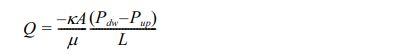
The carbonization process to produce BCMs slowly heats the natural wood precursor in an inert atmosphere to a temperature above 800 °C. To avoid collapse of the specimen structure during the carbonization process, the specimens were slowly heated in N2 gas flow of 10 cm3/min in a horizontal electric furnace at a heating rate of 0.5 °C/min to 600 °C for (6-8) h. Subsequently, the temperature was raised to 1,100 °C at a rate of 3 °C/min to obtain porous carbon materials, as shown in Fig. 1(a). CNTs were synthesized on the BCMs using hydrocarbon gas of acetylene (C2H2) at a high temperature of 650 °C of 60 min in Ar atmosphere. After the carbonization process, LTA templates were synthesized and coated in and out of the BCMs by an in situ method. Co-, Fe-, Cu-, and Ni- metal catalysts on BCMs were loaded on the LTA template under the wetting process. Finally, Fig. 1(c) shows that CNTs were synthesized by the CCVD method.
Characterization
Field emission SEM (FESEM, FESEM LEO 1530 VP) was measured at an acceleration voltage of 1.0 kV. High-resolution transmission electron microscopy (HRTEM, JEOL JEM-3011) was performed at an acceleration voltage of 200 kV. Powder X-ray diffraction (XRD, Rigaku D/max 2500 VL/PC) was performed using Cu Kα radiation (40 kV, 40 mA, k = 1.5418 Å). The pattern was recorded from 2θ = (10 to 70)° and in 0.04° steps with a counting time of 2 seconds per step. Thermogravimetric analysis (TGA, Seiko Extar 7300, TG/DTA 7300) was used to measure the amount of carbon deposited in the experiment using an approximately 5 mg sample heated in air from (298 to 1,073) K at a heating rate of 10 K/min. Raman spectroscopy (Raman system FRA-106/S) was performed using a 1,064 nm (Nd-YAG) laser excitation line
Permeability analysis
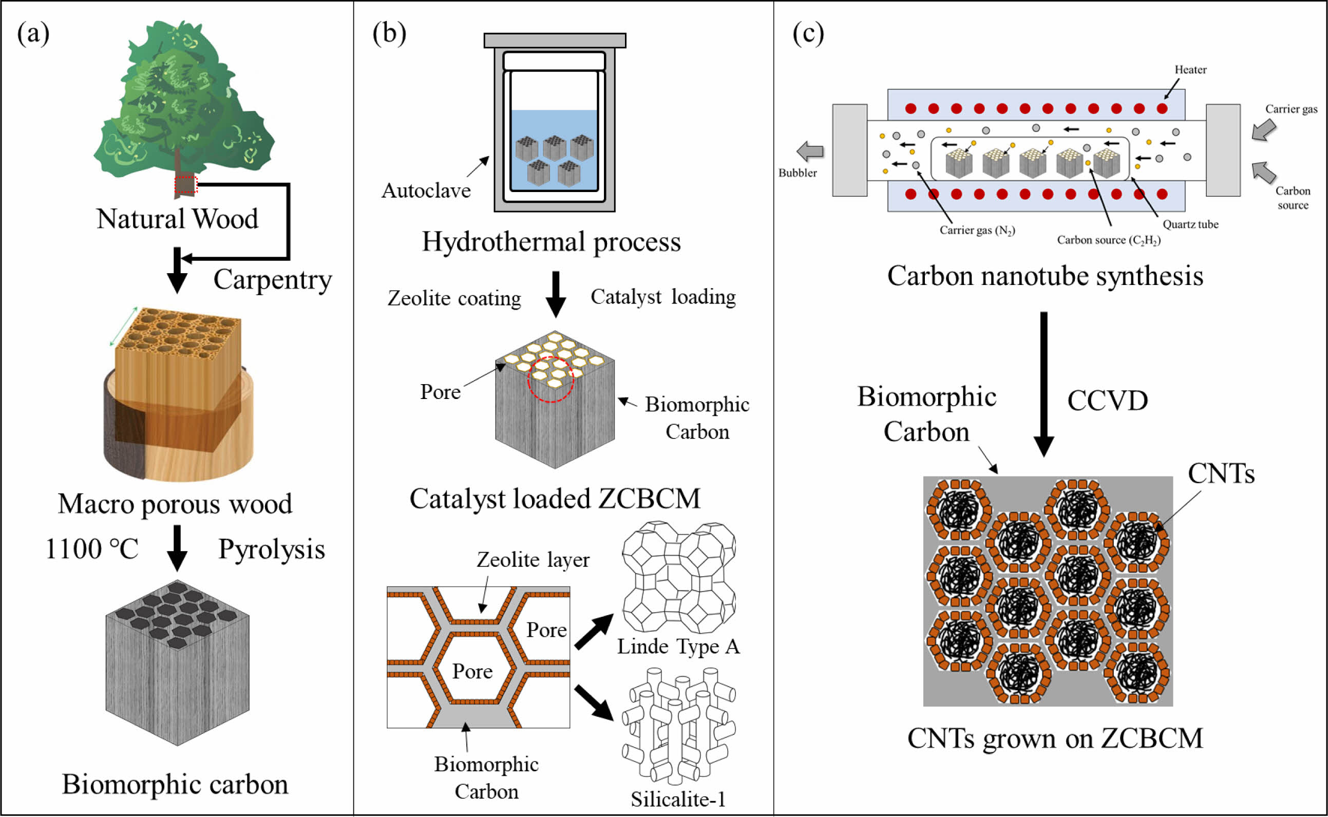
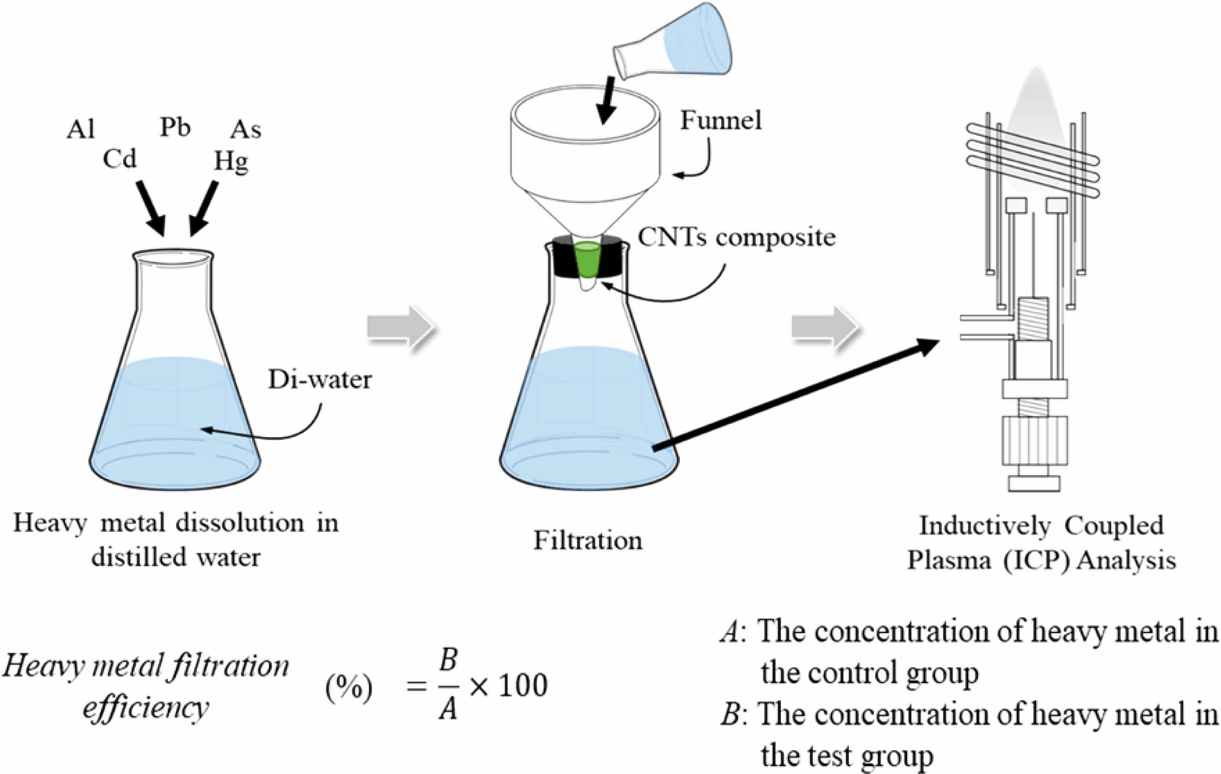
The permeability evaluation through Darcy’s law was carried out by designing a unique custom device. The skeleton was constructed using prefabricated angle steel. Polyurethane (PU) tubing having a diameter of 6 mm was used to construct the inlet/outlet of nitrogen. A one-touch fitting was installed to mount the sample in the central part of the device. Two pressure gauges were fitted to measure the pressure applied to the front and back of the sample. A bubble flow meter was attached to the exhaust to measure the flow of the passed gas fluid. The sample was mounted on a PMMA cuvette cut on both sides, and wrapped several times using a Teflon thread seal tape to prevent gas leakage. A one-touch fitting with a diameter of 6 mm was firmly fixed with epoxy glue to both ends of the cuvette. The gas flow was measured using a bubble flow meter, while N2 of the appropriate pressure was applied as shown in Fig. 2. The permeability of CNTs - BCMs was calculated as follows:
where, Q is the flow rate of gas (m3/s), A is the cross-sectional area of the sample (m2), Pup and Pdw are the upstream pressure and downstream pressure of the sample tube (Pa), μ is the viscosity of flow gas (Pa·s), and L is the length of the sample (m).
Heavy metal ion adsorption analysis
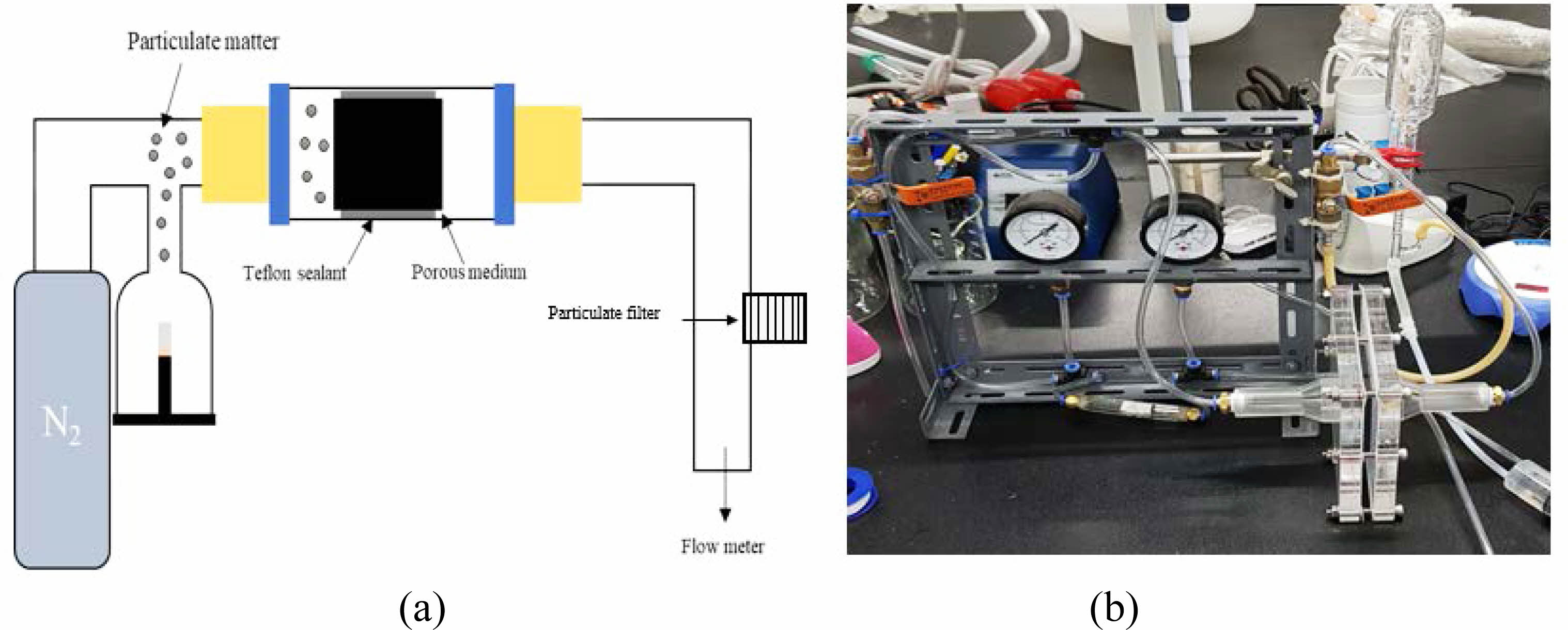
Figure 3 shows the heavy metal filtration performance of the CNTs-BCMs filter using ICP-OES. First, a 100 ppm standard solution (Quality Control Standard 21, PerkinElmer Pure), in which heavy metals were dissolved and diluted with distilled water to (5, 10, and 20) ppm, to prepare a calibration curve with 2% of aqueous HNO3 as a rinse solution. Second, Chromium (VI) oxide, Manganese (II) chloride, lead (II) acetate trihydrate), cadmium sulfate 8/3-hydrate, and Copper (II) chloride (all from Sigma-Aldrich) were dissolved in distilled water to prepare (10 ± 2) ppm samples. CNTs-BCMs were loaded into a cylindrical cartridge having a diameter of 10 mm and a height of 10 mm. They then functioned as a filter by adding 20 mL of the prepared heavy metal solution (Fig. 3). The filtered solution was passed through a maximum 10,000 K of inductively coupled plasma to generate a spectrum, and we analyzed the filtered concentration against the calibration curve. The solution before and after the filtration was analyzed twice, and the value was calculated using the following equation by the reduced value:

where, R is the reduction rate, A is the concentration of the filtered heavy metal solution, and B is the concentration of the initial heavy metal solution as a control group, respectively.
|
Fig. 1 Schematics of the synthesis of CNTs on BCMs: (a) pyrolysis, (b) template coating and catalyst loading, and (c) CNTs synthesis. |
|
Fig. 2 (a) Schematic of the permeability analysis, and (b) photo of the device. |
|
Fig. 3 Schematic of the heavy metal adsorption of the CNTs-BCMs nanofilter. |
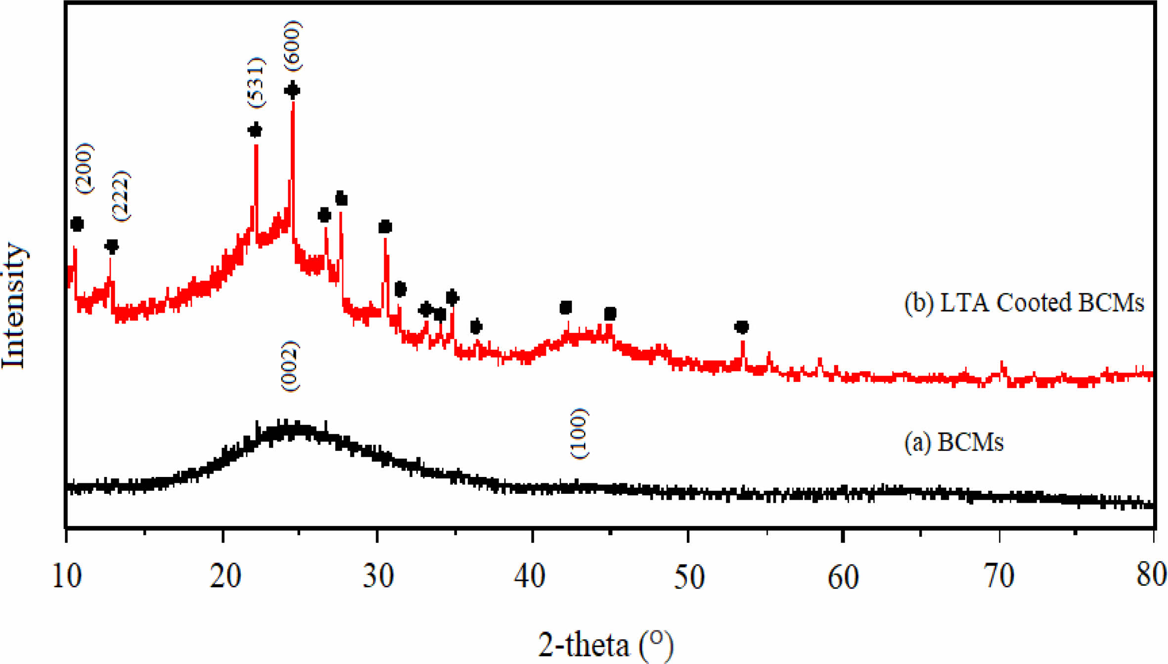
Fig. 4 shows XRD plots of the LTA template synthesized on the surface of the BCMs by an in situ method and BCMs by the pyrolysis of Cypress in Ar atmosphere. These peaks were then compared to JCPDS files. Compared to JCPDS file # 97-002-4901, the corresponding peaks reflected the yield of LTA phase, 2θ = 10° (220), and 24° (600). A single-phase with an average lattice constant of 24.61 Å was found in the obtained XRD. This is a simple cubic arrangement of eight tetrahedra with D4R [14]. The XRD patterns of BCMs agree well with the standard JCPDS file (41-1487), which confirms the formation of the crystalline structure of graphite carbon. The obtained diffraction peaks are indexed to the corresponding peaks for (002) and (100) at the 2θ = (24 and 43)° crystal planes of graphitic carbon, respectively [17].
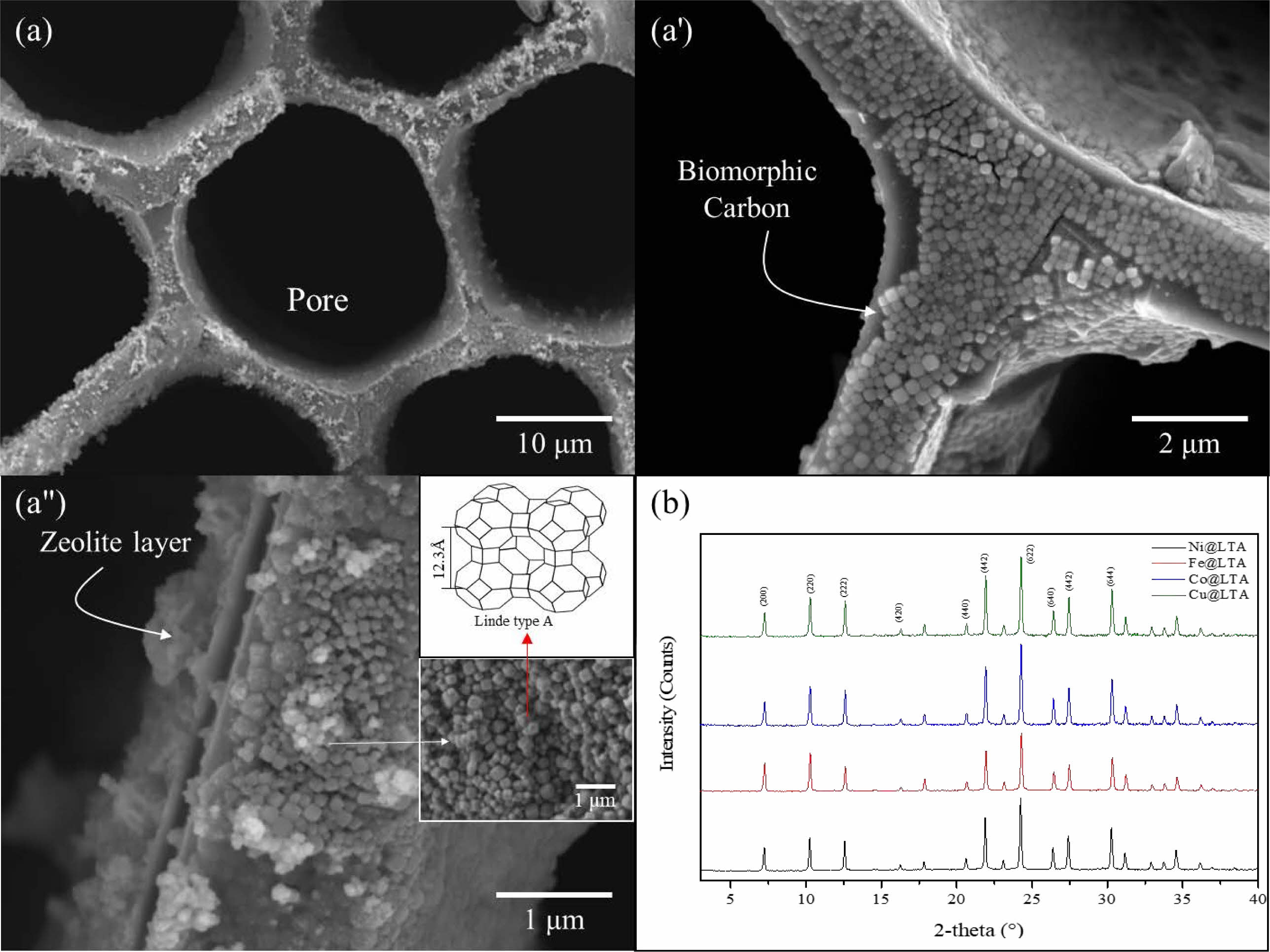
Figs. 5(a) & (a') show the hexagonal cell structure of BCMs, with BCMs pore size of (18.8 to 23.7) μm, and each cell wall thickness of about (2.30 to 1.40) μm. Most of the cell pores have a rectangular shape, showing a regular net shape with carbon walls bonded together. The compressive strength of BCMs with a pore size of 19.60 μm and a wall thickness of 2.3 μm is 52.65 MPa. LTA template is uniformly coated on the inside and outside of the BCMs honeycomb structure, which can be observed in Figs. 4(a') & (a''). LTA crystals are well-developed cubic crystals coated in fine layers. The size of these crystals is about 120 nm. Fig. 5(b) is an XRD pattern in which a very small amount of metal catalyst is supported on the LTA crystal. The corresponding peak with the standard JCPDS file (97-002-4901) shows an LTA single phase, 2θ = 7° (200), 10° (220), 13° (222), 22° (531), and 24° (600), respectively [9].
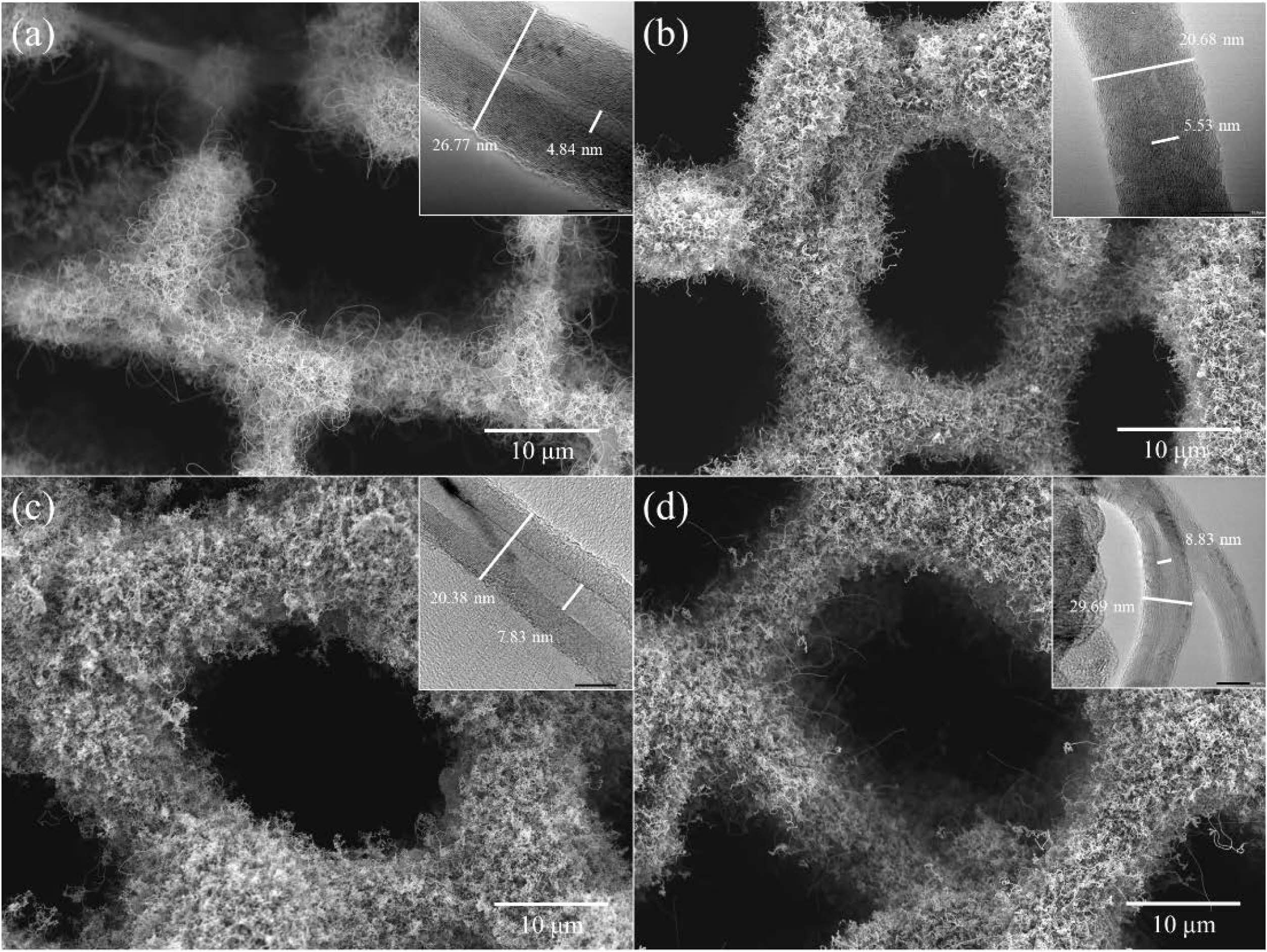
Fig. 6 shows the FESEM and TEM images of CNTs grown at 650 °C for 60 min on BCMs loaded with Fe-, Cu-, Ni-, and Co- metal catalysts. All CNTs grew uniformly and firmly in and around the BCMs. The synthesized CNTs are built into a more entangled and tighter network throughout the LTA-coated BCMs. All CNTs were synthesized with multi-layered carbon nanotubes such as hair, and the yield of CNTs was very good in Ni- and Co- loaded BCMs, as shown in Figs. 6(c) & (d). The figures show the high yield of 15.50 % and crystallinity in the breathable BCMs with 1.02 × 10⁻⁷ m3/s XYZ. Their structure is thought to be because the gaseous carbon starting materials can be distributed on the catalyst surface particles. Hence, it can be assumed that the decomposition of carbon atoms from C2H2 forms coaxial cylindrical graphene sheets layer-by-layer around the CNTs core [15].
The TEM image in Fig. 6(c) shows a small outer wall of a CNT with a diameter of about 20.38 nm and an inner diameter of 7.833 nm. The outer wall of the CNTs synthesized in Fig. 5(d) is relatively thick, and the outer and inner diameters are about (29.69 and 8.83) nm, respectively, and have a dense layered structure. The basic growth mechanism of CNTs is known for their better adhesion tendency to the substrate [18]. All CNTs are MWCNTs with bamboo-like structures. In the cluster containing Cu metal, a belt-shaped carbon material was formed instead of the CNTs.
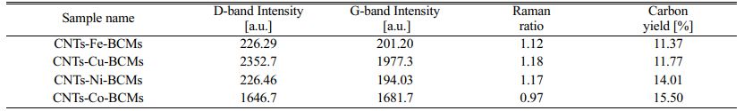
All CNT samples show an initial weight loss tendency up to 195 °C, which can lead to loss of water physically adsorbed by the zeolite [19]. In the subsequent heating process of TGA, all samples undergo a two-step weight loss pattern. In the first stage of (100 to 250) °C, amorphous carbon is burned; and in the second stage (≥450 °C), MWCNTs are respectively burned from (580 to 610) °C. The carbon yield of CNTs synthesized by CCVD is calculated as follows:

where, mcat is the initial catalyst amount (before reaction), and mtot is the total sample weight after synthesis [20]. All CNTs samples show the weight loss of (85-90)% (Table 1).
In the Raman spectra results, two strong peaks can be observed within the wavelengths (1,340 and 1,600) cm−1, designated as D- and G-bands, respectively. In all Raman spectra, MWCNTs, a characteristic of a disordered sp2 hybrid carbon material, was observed. The D-band indicates defects in the graphite crystal, while the G-band corresponds to the tangential stretching (E2g) mode of highly oriented pyrolytic graphite, and indicates the presence of crystalline graphite carbon in MWCNTs. The intensity of the D-band against the G-band measures the degree of CNT defects and crystal phase development, and is used for the qualitative characterization of nanotubes [21].
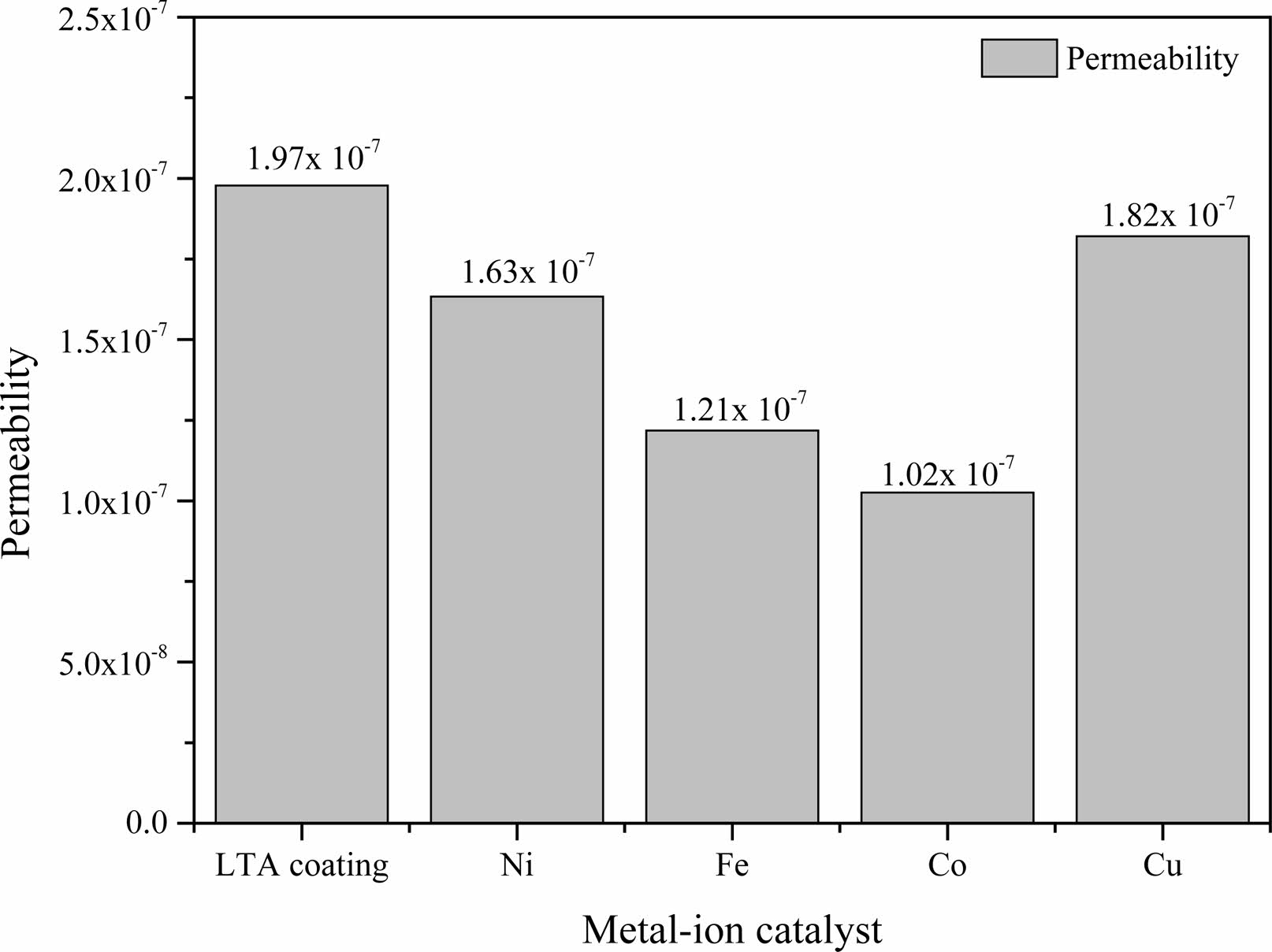
Fig. 7 shows the permeability of the synthesized CNTs at 923 K for 60 min on various catalyst-supported LTA-coated BCMs. As CNTs were synthesized for all samples, the overall permeability was lowered. The permeability of LTA-coated BCMs without CNTs as a control were measured to be 1.97 × 10⁻⁷ m-2. On the other hand, the permeabilities of CNTs-BCMs loaded with Cu-, Ni-, Fe-, and Co- catalysts were (1.82, 1.63, 1.21, and 1.02) × 10-7 m-2, respectively, depending on the type of loaded catalyst. The largest difference from the control group was the Co- catalyst loaded CNTs-BCMs, which was 51.82% different. The permeability decreases because the synthesized tangled CNTs interfere with the gas flowing through the filter. In addition, there was a difference in permeability according to the synthesis yield of CNTs, so the CNTs-BCMs loaded with Co catalyst having the highest synthesis yield of 15.50% showed the lowest value of permeability of 1.02 × 10⁻⁷ m2 (Table 1):
To test the effectiveness of an adsorption process, the amount of pollution that was successfully removed from the solution during the adsorption process is precisely calculated. In general, the performance depends on the adsorption capacity of the specified CNTs materials, which in turn is characterized by several variables, such as the surface area, yield of active sites on the adsorbent’s surface, and the degree of attraction between the used materials and the heavy metals [22]. Table 2 show the results of quantitative analysis using ICP-OES for filtrates in which heavy metal ions were filtered on carbon nanotube-grown samples according to the type of catalyst. Five heavy metals were removed from all samples, and Pb showed more than 99.99% complete filtration efficiency. In detail, the heavy metal solution contained Mn, Cu, Cr, Cd, and Pb, and the initial concentrations before filtration were (10.82, 11.54, 11.62, 12.50, and 10.61) ppm, respectively. The filtrate that was passed through the CNTs–BCMs contained in the cartridge was reduced to less than 1 ppm in all heavy metals by the adsorption performance of CNTs, which can adsorb up to 92.3 mg/g of Pb on a single metal [22]. In addition, the adsorption performance differed according to the yield of CNTs.
Table 2 shows that the highest filtration efficiency was achieved in the highest yield of CNTs Co LTA samples.
|
Fig. 4 XRD patterns of (a) BCMs, and (b) LTA-coated BCMs. |
|
Fig. 5 FESEM images of (a) BCMs, (a') & (a'') LTA-coated BCMs, and (b) XRD pattern of metal catalyst loaded LTA-BCMs |
|
Fig. 6 FESEM and TEM (Inset) images of multi-walled CNTs grown on Fe-, Cu-, Ni-, and Co- loaded LTA-BCMs for 60 min at 650 °C for 60 min. |
|
Fig. 7 Permeability of the CNTs grown on various catalyst-loaded LTA-BCMs. |
|
Table 1 Raman Spectra and the Carbon Yield (TGA) of Carbon Nanotube-BCMs at 650 °C for 60 min with respect to various Catalysts. |
|
Table 2 Result of the Heavy Metal Filtration Efficacy Valueof CNTs-BCMs Filter with Various Catalysts. |
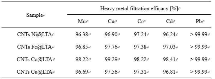
The CNTs grown on Co- and Fe-ion loaded BCMs well-developed hexagonal honeycomb structure shows the permeability of (1.02 and 1.2) × 10-7 m3/s, respectively. All CNTs synthesized on a metal catalyst-loaded BCMs are typical MWCNTs. The microstructure of the MWCNTs showed a wall thickness of (20.38-29.69) nm, and a narrow inner hole of (4.84-8.83) nm. The CNTs grown on the Cu metal catalyst-supported BCMs achieved the highest Raman ratio of ID/IG = 1.18, but the carbon yield was slightly lower at 11.77%. The highest carbon yield (15.50%), and superior quality CNTs were achieved in the co-loaded BCMs. Due to their high aspect ratio and large specific surface area, high-density CNT networks that form pore sizes ranging from micropores to mesopores can be used as filters for gas adsorption, water filtration, and other purification systems. The filtration efficiency of various heavy metals over 98% was observed, and the case of Pb showed perfect filtration efficiency.
This research was supported by the Basic Science Research Program through the National Research Foundation of Korea (NRF), funded by the Ministry of Education (201800790001).
- 1. M.F.L. De Volder, S.H. Tawfick, R.H. Baughman, and A.J. Hart, Science 339[6119] (2013) 535-539.
-

- 2. J.G. Park, S.Y. Kim, I. S. Han, and I. J. Kim, J. Ceram. Proc. Res. 21[2] (2020), 170-191.
-
- 3. J. Ramírez-Rico, J. Martínez-Fernandez, and M. Singh, Int. Mater. Rev. 62[8] (2017) 465-485.
-
- 4. S.Y. Kim, H.U. Kim, Y.H. Seong, I.S. Han, S.K. Woo, and S.H. Kim, J. Porous Mater. 25[2] (2017) 603-609.
-
- 5. J. Kong, A.M. Cassell, and H. Dai, Chem. Phys. Lett. 292[4-6] (1998) 567-574.
-
- 6. J.H. Hafner, M.J. Bronikowski, B.R. Azamian, P. Nikolaev, A.G. Rinzler, D.T. Colbert, K.A. Smith, and R.E. Smalley, Chem. Phys. Lett. 296[1-2] (1998) 195-202.
-
- 7. A.I. Zhbanov, E.G. Pogorelov, and Y.-C. Chang, ACS Nano 4[10] (2010) 5937-5945.
-
- 8. S. Mazumder, N. Sarkar, J.G. Park, I.S. Han, and I.J. Kim, Mater. Chem. Phys. 171[1] (2016) 247-251.
-
- 9. M. Rajabi, K. Mahanpoor, and O. Moradi, RCS Adv. 7 (2017) 47083-47090.
-
- 10. A. Fujiwara, K. Ishii, H. Suematsu, H. Kataura, Y. Maniwa, S. Suzuki, and Y. Achiba, Chem. Phys. Lett. 336[3-4] (2001) 205-211.
-
- 11. R. Das, B.F. Leo, and F. Murphy, Nanoscale Res. Lett. 13[1] (2018) 1-10.
-
- 12. H.Y. Yang, Z.J. Han, S.F. Yu, K.L. Pey, K. Ostrikov, and R. Karnik, Nat. Commun. 4[1] (2013) 1-8.
-
- 13. E.T. Thostenson, Z. Ren, and T.-W. Chou, Compos. Sci. Technol. 61[13] (2001) 1899-1912.
-
- 14. W. Zhao, D.N. Seo, H.T. Kim, and I.J. Kim, J. Ceram. Soc. Jpn. 118[1383] (2010) 983-988.
-
- 15. W. Zhao, H.T. Kim, and I.J. Kim, J. Ceram. Proc. Res. 13[1] (2012), 81-85.
- 16. J.G. Park, S.Y. Kim, Z. Wei, J.H. Jeon, S.Y. Kim, and I.J. Kim, J. Ceram. Proc. Res. 18[2] (2017) 161-165.
- 17. M. Pawlyta J.N. Rouzaud, and S. Duber, Carbon. 84 (2015) 479-490.
-
- 18. M.J. Height, J.B. Howard, J.W. Tester, and J.B. Vander Sande, J. Phys. Chem. B 109[25] (2005) 12337-12346.
-
- 19. Y. Li, X.B. Zhang, X.Y. Tao, J.M. Xu, W.Z. Haung, J.H. Luo, Z.Q. Luo, T. Li, F. Liu, Y. Bao, and H.J. Geise, Carbon 43[2] (2005) 295-301.
-
- 20. C.M. Chen, M. Chen. F.C. Leu, S.Y. Hsu, S.C. Wang, S.C. Shi, and C.F. Chen, Diamond Relat. Mater. 13[4-8] (2004) 1182-1186.
-
- 21. J.H. Lehman, M. Terrones, E. Mansfield, K.E. Hurst, and V. Meunier, Carbon 49[8] (2011) 2581-2602.
-
- 22. T.-X. Fan, S.-K. Chow, and D. Zhang, Prog. Mater. Sci. 54[5] (2009) 542-659.
-
 This Article
-
2022; 23(5): 559-565
Published on Oct 31, 2022
- 10.36410/jcpr.2022.23.5.559
- Received on Sep 23, 2020
- Revised on Oct 12, 2021
- Accepted on Oct 16, 2021
Services
- Abstract
introduction
experimental setup
results and discussion
conclusions
- Acknowledgements
- References
- Full Text PDF
Shared
Correspondence to
- Ik Jin Kim
-
Institute for Processing and Application of Inorganic Materials, (PAIM), Department of Materials Science and Engineering, Hanseo University, 46, Hanseo 1-ro, Haemi-myun, Seosan-city, Chungnam 31962, Korea
Tel : +82-41-660-1661 Fax: +82-41-660-1661 - E-mail: ijkim@hanseo.ac.kr
Clean-Energy Research Institute(CRI), Hanyang University, 222, Wangsimni-ro, Seongdong-gu, Seoul, 04763, Korea
E-mail: jcpr@hanyang.ac.kr