


- Experimental investigation in the selection of blank material during deep drawing process using finite element analysis
Sangeetha Na,*, Brathikan V Mb, Nitheeshwar R Kc and Jayabalu Sc
aSenior Associate Professor, Kumaraguru College of Technology, Coimbatore, India, 641049
bAssistant Professor, Kumaraguru College of Technology, Coimbatore, India, 641049
cStudent, Kumaraguru College of Technology, Coimbatore, India, 641049This article is an open access article distributed under the terms of the Creative Commons Attribution Non-Commercial License (http://creativecommons.org/licenses/by-nc/4.0) which permits unrestricted non-commercial use, distribution, and reproduction in any medium, provided the original work is properly cited.
Deep Drawing is the forming process where the shape of the punch is projected to the blank by the application of force with the help of a die and blank holder. Obtaining a quality product in the deep drawing process mainly depends on the characteristics of blank materials. The deep drawing process influences the process parameters like blank holder force, coefficient of friction for the lubricants, etc. The deep drawing process was conducted using a hydraulic press machine with a maximum capacity of 50 Newton for blank materials like cold roll steel, stainless steel, aluminum alloys, and tungsten. The blank force required for the deep drawing process was investigated on various materials and analysed with the material properties. The Finite Element method is used to check the quality of the deep drawing product by applying various forces obtained in the experimental methods. Shear Stress and Strain obtained in the product during the deep drawing process were studied and verified with the analytical stress and strain. It was found that ductile material yields a very good drawing ratio whereas brittle material such as Titanium has very little drawing ratio which could be further enhanced by the combination of reinforcement or a mixture of allied metals
Keywords: Deep Drawing, lubricant, Blank material, Sheet metal, Coefficient of friction
The development and up-gradation of deep drawing are needed and very important in industries and that gives many advantages like reducing wastages in time, material, and tools which improves the quality and time, increasing productivity [1]. The force required for the holder to hold the blank is also a very important and unavoidable parameter that is to be maintained properly. The blank holder force should be maintained properly unless some defects like cracks, tearing, wrinkling, etc., will be developed during the process so the holding force should be determined correctly and maintained properly [2]. Since the friction coefficient of oil and stiffness of the material determines the blank holder force, a clear study is done on the blank material and lubricants, used in the drawing process. As this is complicated work to do, a computer-optimized system is implemented to get higher accuracy and quality of the product outcome [3]. The characteristics of the oil used as lubricant makes a significant effect on the drawing process which reduces the weariness of the tool and reduces friction which in turn reduces the heat between the punch and blank. Thus, the quality of the output product increases, and the accuracy of the dimension is also remarkably close to the actual dimension. The energy consumption in forming the product has been reduced [4]. Plevy found that compared to oil lubricant, a solid polymer film lubricating barrier is more efficient when coated on sheets used as blanks which reduce the energy consumption to draw the desired job. When we use polymer film as a lubricant instead of oil the friction between the punch, die & blank is reduced even when it has low clearances between each part [5].
Sometimes brass is used as blank material for decorative purposes since it has improved properties as compared to steel-like conductivity of heat and electri- city and any metals can be used for this purpose for their usage based on the process supporting material properties. The required properties must be obtained by doing many experiments. Through various experiments, various data are obtained which would be helpful in determining the parameters suitable for the drawing process [6]. By using the coulomb formula, the friction coefficient is found. And the precision evolution is found by the extensometer. In the manufacturing field, many processes are used to manufacture products, and forming of the product without material removal has the greatest scope among the manufacturing sectors, deep drawing satisfies these conditions. And most aerospace and automobile casing and body parts are manufactured using the deep drawing process [7]. The suitable parameters could be obtained after analysis of the deep drawing with the necessary conditions. There are two main types of analysis to analyze the deep drawing process. First, an experiment is conducted to find the parameters to obtain zero defective products. Another is the numerical method; this can be done faster than the experimental method as it doesn’t require any experimental trials to be performed. The deformation in the flange is mainly by shear deformation and the deformations are not in the path of strain for a circular blank that is used to draw circular objects. The ability to draw the object from its blank is related to, the diameter of the blank which is taken initially, and the parameters of the desired product. Finite element analysis is used in the analysis of the square deep drawing process for laminated steel brass sheet metals [8].
For the various types of blank material used, FEA is done to find the effect by varying the loads, resulting from variation in the thickness & strain during the end of this process. Different parameters were used and analyzed to get the highest drawing force [9]. The optimization, geometric characterization, and development of blank are demonstrated [10-11]. During high tem- peratures, the wear characteristics of silicon carbide ceramics are investigated [12]. The effect of friction and wear characteristics for silicon nitrite mainly depends on the amount of silicon dioxide nano-colloid present [13]. The investigations revealed that the wear properties are reduced by the inclusions of mullite, and aluminium titanate added to porcelain ceramics [14]. Wear properties and bending strength of the composites reinforced with additives; silicon oxide and titanium oxide are studied [15]. The calcium oxide, magnesium oxide added to stabilized zirconia ceramics produced by different pressing methods are investigated for their wear properties [16]. Gray cast iron machining is demon- strated to study the cutting performance and wear mechanism of tungsten carbide and cobalt ultrafine cemented carbide [17]. Optimization techniques are used for multi-objective functions to obtain optimal process parameters and they can be applied to all manufacturing processes [18, 19]. Several optimization techniques are followed for the assessments of machinability of the manufacturing process and these optimization techniques are helpful in determinization of the optimum machining process parameters [20-23].
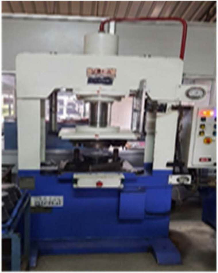
Based on the survey, the main objective of this work is framed as to study the effect of blank material properties affecting the product quality by a computational technique using Abaqus, mathematical calculations by using necessary formulas & experimentation work using a hydraulic press machine of maximum load capacity of 50 newtons.
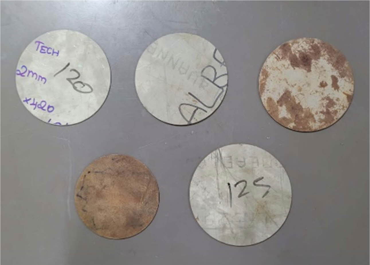
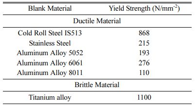
The calibration of the machine is done, and the specified pressure of the punch is preset during its action. Next, the pressure to hold the workpiece during punching is set depending upon the thickness of the blank used. During the drawing process, the punch moves towards the blank at the specified pressure. The machine is controlled by two modes: manual and automatic. The down and up movement of the punch is fully controlled manually via buttons. The punch moves when the button is pressed and returns when the button is released in automatic mode. It has safety sensors on each side to directly punch on the blank and detect human interruption during the method and that will enhance the safety of operators. The blank materials of various properties are selected based on the appli- cation for this study. The detail of the blank materials and their yield strength is mentioned in Table 1.
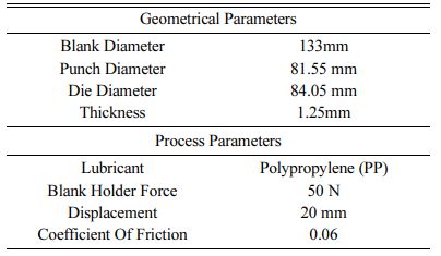
The selected materials fall under the category of ductile and brittle materials based on their properties. All the metals considered are ductile materials, whereas titanium falls under brittle material. The experiment was carried out only by varying the material and maintaining the rest of the geometrical and machining parameters constant. The parameters that are considered for this process are mentioned in Table 2.
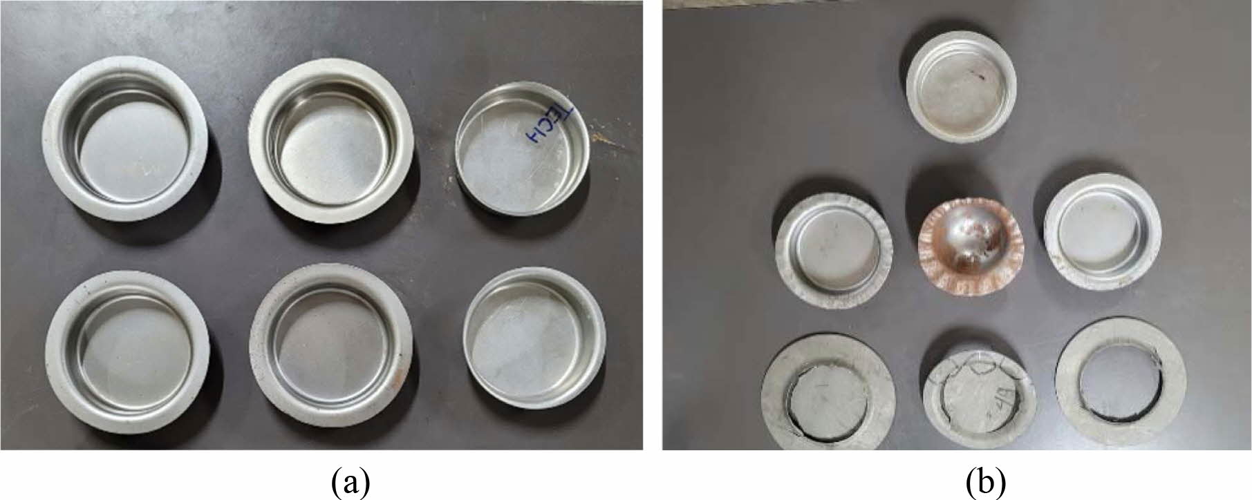
The Table 2 displays the geometrical parameters & process parameters that have been maintained constant while performing this experiment. The punch force and time required for drawing were noted respectively. When Titanium was used as blank material it was found to be a failure during the deep drawing process, cracks were developed as its brittleness property dominates during the process.
The maximum loading capacity of the machine can reach 50 tons. It is equipped with a 5-horsepower motor. The dimensions of the machine bed are 500 ´ 500 mm.
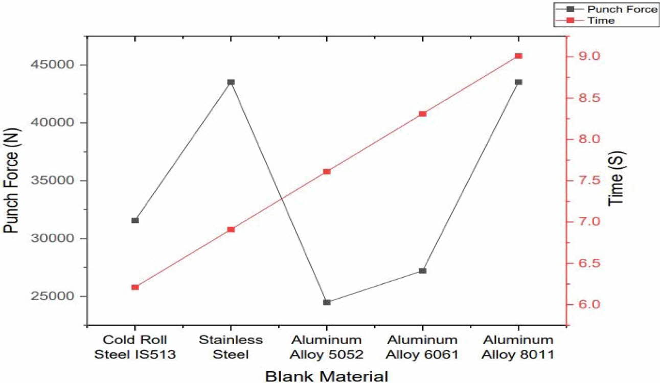
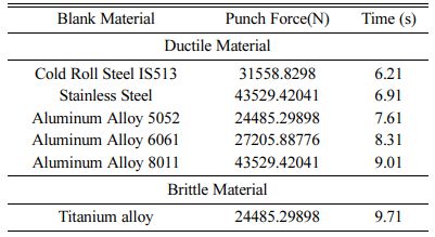
The Table 3 displays various types of blank material used during the experiment and also shows that the punch requires various forces according to the materials used. Here the punch force and time were high for Aluminum Alloy 8011 & least for Cold Roll Steel IS513.
Fig. 3 shows that aluminium Alloy -8011 and stainless steel require more force than the other given metals. As well as an aluminium alloy – 5052 requires lower force than other metals but the time taken to draw the object is mostly the same for all metals. This is the result obtained while experimenting with the process. Fig. 1 2 4 5
Inference
Each material has unique properties, so the for- mability ratio is different. Due to this reason, various punch force is required for the drawing process. Even though Titanium metal is a brittle material, and it is not suitable for the deep drawing process, experiments were conducted on titanium material to study the failure mode on force on which it started to fail, and time taken for the same.
|
Fig. 1 Aluminium and mild steel blanks. |
|
Fig. 2 Deep Drawing Machine. |
|
Fig. 3 Blank Material vs Punch Force & Time |
|
Fig. 4 (a) Drawn Product and (b) Defective Product. |
|
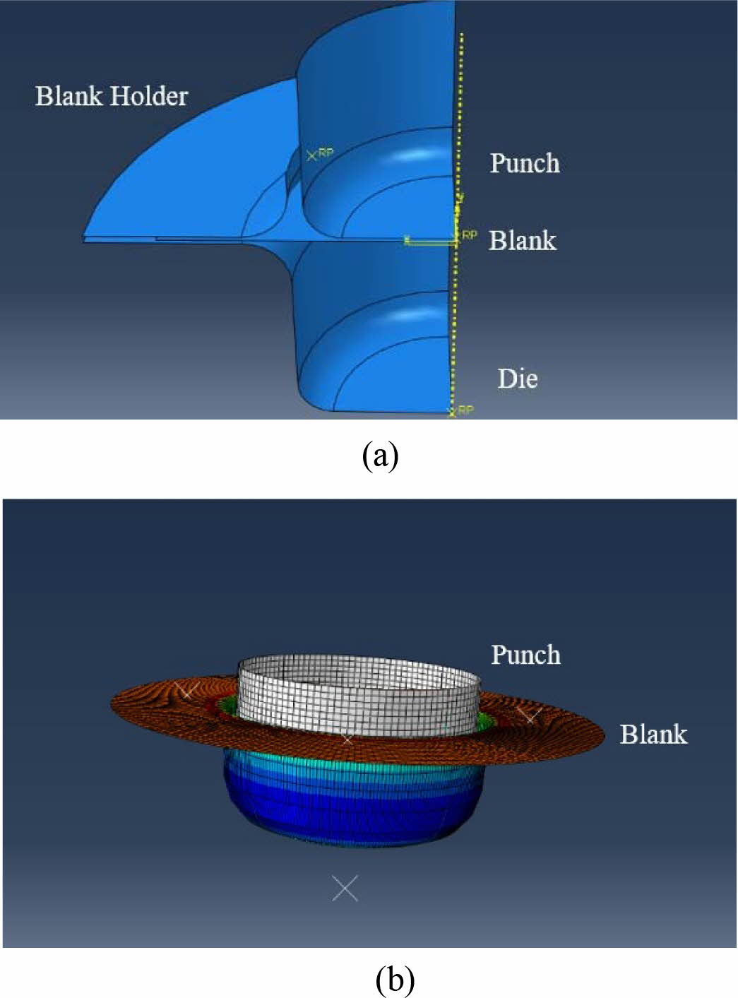
Fig. 5 (a) 3D model of the quarter blank and (b) Finite Element model of the blank. |
|
Table 3 Types of blank material used & its process parameters by experimental analysis |
Punching force (P) required for deep drawing process of various material is obtained using the basic formula, p = πDtσy. The Punch Force (P) is calculated using blank dimeter and the yield stress of the various material used in this experimentation process. BHF is calculated as the 1/3rd of the required punch force for the process.
The punch force concerning the friction force (P) is calculated by using the formula, P = [(πdt(1.1σ) In(D/d)) + [2Hd/D]e(μπ/2)]+B. The induced stress during the drawing process can be found by σ1 = p1/(π/4) [d12 -(d1 - 2t)2 [11].
The punching force, blank holder force required for all the blank materials are calculated and listed in Table 3.
Explicit Dynamic Analysis was also carried out to predict the punching force. Stress and strain value of the blank material under deep drawing process is also studied for all the experimental cases to verify the results obtained during the experimentation. Using ABAQUS software the 3D model of the punch, blank, die and blank holder are created. Further the 3D model is assembled with the necessary constrains such that the blank material is drawn in from the edges and therefore slides in-between the holder and the holder and the die. The outer edge of the blank is clamped, inwards. This is achieved by defining the displacement to punch, that draws the blank towards the die creating the required shape. Blank holder is assigned with force to hold the blank material during the process. The contact between the punch, blank and die is induced with a friction coefficient of 0.1. Simulations are run and analyzed for different blank materials used and keeping the rest of the parameter constant. Finally, the required data obtained are presented in the form of a table, and a graph.
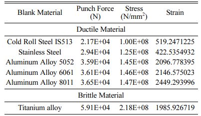
Table 4 shows that it requires various force is required for various materials and stress, and strain also varies. Here Punch force, stress & strain was high for Titanium alloy and least for Cold Roll Steel IS513.
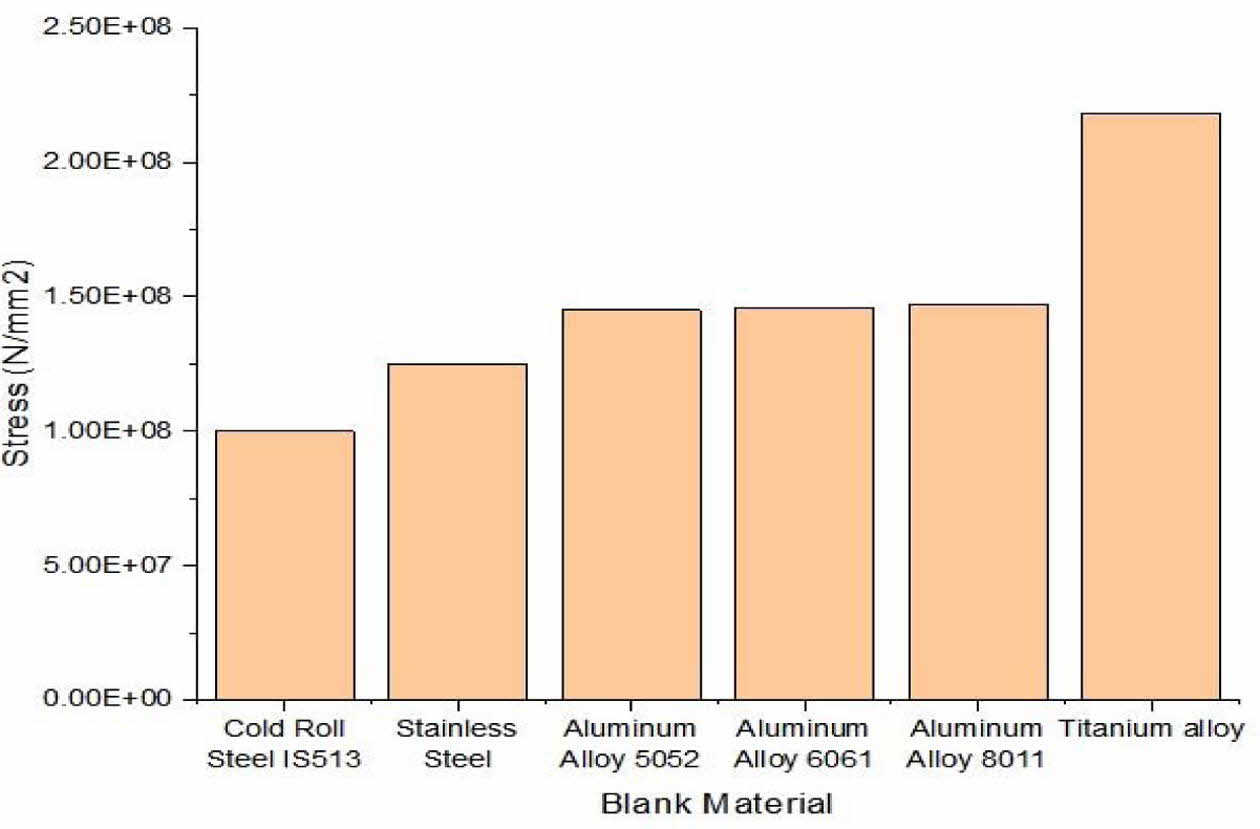
Fig. 6 represents the induced strain concerning the blank material during the metal forming process. Aluminum alloy 8011 produces more strain but stainless steel produces the least. It shows Aluminum alloy 8011 can withstand more load than others by mathematical analysis.
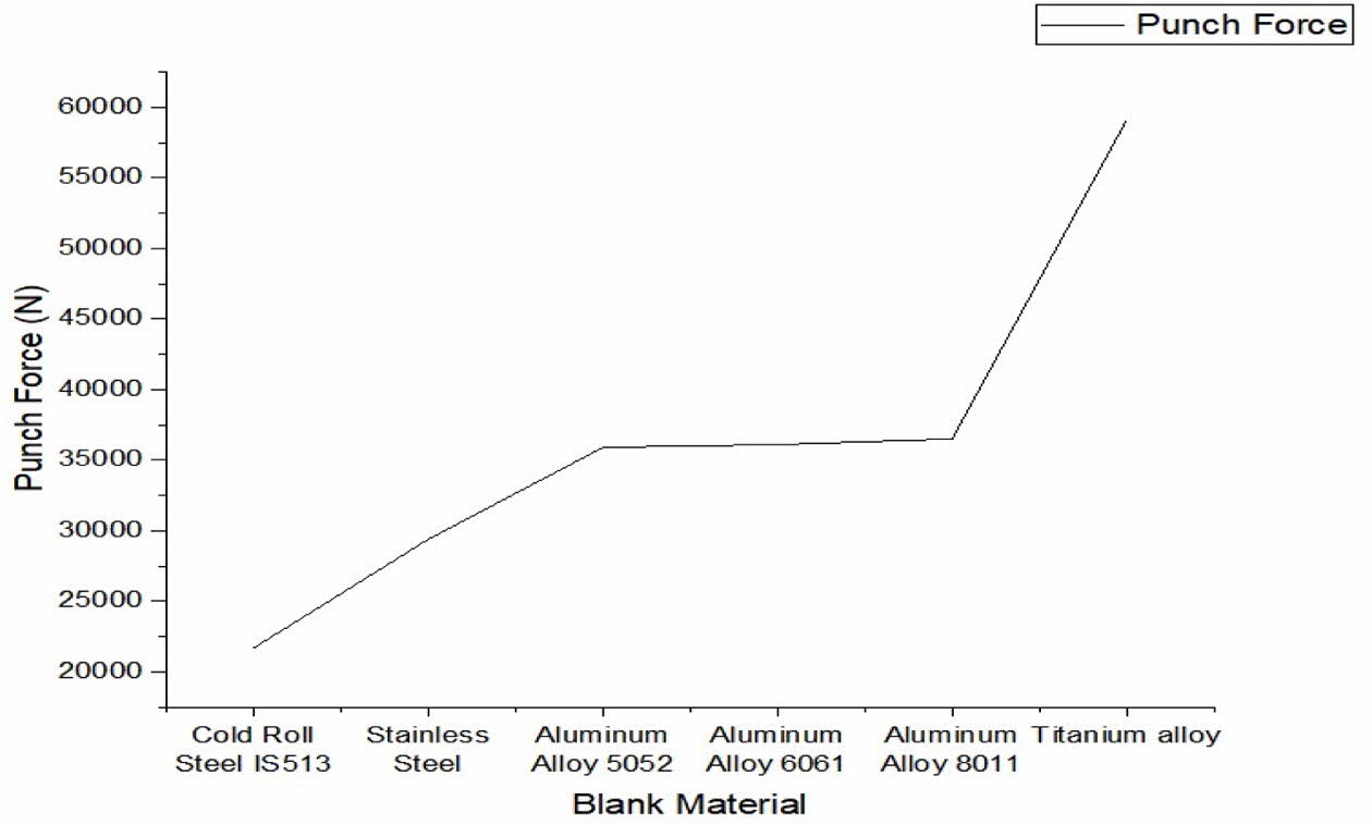
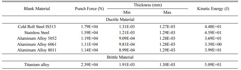
Fig. 7 shows that the aluminum alloys require mostly the same punch force on calculation as the properties are very similar to each other. Table 5 shows that there is no major difference in thickness when the material is varied. Here the punch force was maximum for Titanium Alloy and least for Cold Roll Steel IS513. The Kinetic Energy is maximum for Titanium alloy & least for Aluminum Alloy 6061.
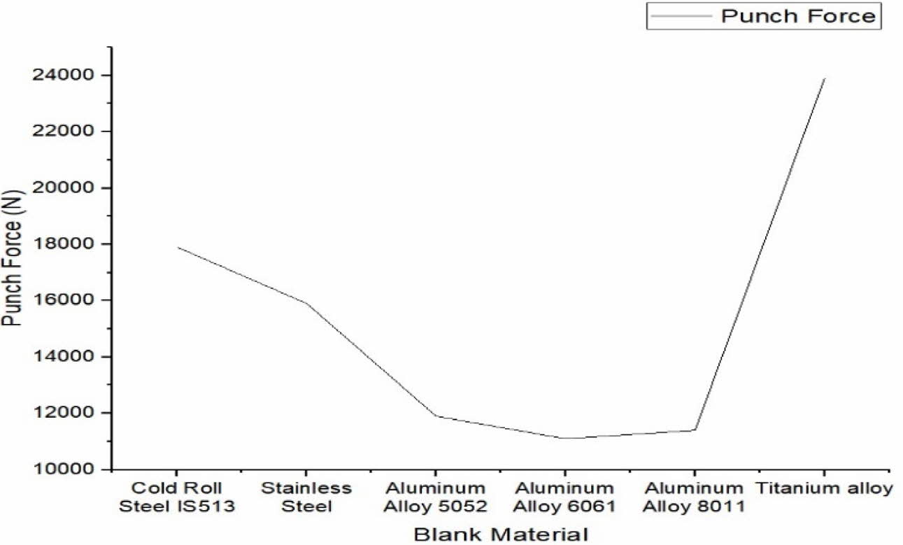
Fig. 8 represents that titanium is the toughest and more brittle metal, the titanium metal breaks at low temperature. For deforming process, the metal should be heated, and then it should undergo a deformable process.
Inference
Due to various material properties, the drawing ratio differs from material to material hence various punch force is required during the deep drawing process. It is observed that the punching force required for the Cold Roll Steel is high since it has high yield stress comparing to all the materials that are considered in this study. The change in young’s modulus bring the variation in strain also. Since titanium is a brittle material, the drawing ratio for Titanium must be high during the process of forming, if not the metal may break during the forming process. This was analyzed using the Finite Element Method.
|
Fig. 6 Stress with respect to blank material obtained by mathematical calculation. |
|
Fig. 7 Punch force required for various materials obtained by mathematical calculation. |
|
Fig. 8 Various material vs Punch force in FEA. |
|
Table 4 Types of blank material used & its process parameters by mathematical calculation |
This paper made us, how the blank material plays an important role in the workflow of the material. Improper selection of material without analyzing the properties i.e., ductility, and malleability leads to the crack which results in the failure of the product. Punch force also depends on the blank materials used. Stress varies with respect to the punch force. Blank holder force also differs concerning blank materials to ensure the smooth flow of the material and to avoid wrinkles and tears. Thus, all the parameters considered in this research work are correlated with each other playing an important role in determining the product quality.
This project work would not have been possible without the financial support of Kavi Techno Works, Coimbatore & Kumaraguru College of Technology, Coimbatore. I am especially indebted to Kavi Techno Works, Coimbatore for providing us with this problem statement & who has been supportive during this project. We would especially like to thank the research cell Kumaraguru College of Technology, Coimbatore for their professional guidance.
- 1. S. Thiruvarudchelvan and M.J. Tan., J. Mater. Process. Technol. 192 (2007) 8-12.
-

- 2. R.V. Reddy, T.A.J. Reddy, and G.C.M. Reddy, Int. J. Eng. Trends Technol. 3[5] (2012) 669-676.
- 3. R. Sajja and S. R. Chalamalasetti, Int. J. Adv. Appl. Math. and Mech, 1[3] (2014) 109-120.
- 4. H. Hoffman Met. Form. Handbook. Springer Science & Business Media. (1998).
- 5. H. Naceur, Y.Q. Guo, J. L. Batoz, and C. Knopf-Lenoir, Int. J. Mech. Sci. 43[10] (2001) 2407-2434.
-
- 6. R.H. Wagoner and J.L. Chenot, Wagoner. Metal forming analysis, Cambridge University Press (2001).
-
- 7. G.E. Dieter and D. Bacon, Mechanical metallurgy [3] (1976).
- 8. H.A. Ameen, IRAQI J. Mech. Mater. Eng. 20[1] (2020) 12-24.
-
- 9. C.P. Singh and G. Agnihotri, Mater. Today: Proc. 4[2] (2017) 2411-2418.
-
- 10. H. Gharib, A.S. Wifi, M. Younan, and A. Nassef, J. Achiev. Mater. Manuf. Eng. 17[1-2] (2006) 245-248.
- 11. A. Aminzadeh, S.S. Karganroudi, and N. Barka, Int. J. Adv. Manu. Tech., 117[3] (2021) 1193-120.
-
- 12. S.H. Ahn and K.W. Nam, J. Ceram. Process. Res. 18[11] (2017) 767-776.
- 13. S.H. Ahn and K.W. Nam, J. Ceram. Process. Res. 17[10] (2016) 1046-1051.
- 14. T.Boyraz and A. Akkuş, J. Ceram. Process. Res. 22[2] (2021) 226-231.
-
- 15. S.H. Ahn and K.W. Nam, J. Ceram. Process. Res. 22[1] (2021) 54-60.
-
- 16. A. Akkus and T. Boyraz, J. Ceram. Process. Res. 19[3] (2018) 249-52.
- 17. J. Chen, M. Gong, and S.H. Wu, J. Ceram. Process. Res. 16[2] (2015) 244-248.
- 18. R. Thirumalai, J.S. Senthilkumaar, P. Selvarani, and S. Ramesh, Proc Inst Mech Eng C J Mech Eng Sci. 227[9] (2013) 1889-1897.
-
- 19. R. Thirumalai and J.S. Senthilkumaar, J. Mech. Sci. Technol. 27[4] (2013) 1109-1116.
-
- 20. R. Thirumalai, M Vivekraj, J. Ceram. Process. Res. 23[2] (2022) 228-232.
-
- 21. R. Thirumalai, S. Karthick, M. Giriraj, J. Ceram. Process. Res. 23[2] (2022) 221-227.
-
- 22. Mukeshkumar, S.K. Tamang, Dipika Devi, M. Dabi, K.K. Prasad, and R. Thirumalai, J. Ceram. Process. Res. 23[2] (2022) 373-382.
-
- 23. M. Sivaperumal, R. Thirumalai, S. Kannan and K.S.S. Rao Yarrapragada, J. Ceram. Process. Res. 23[2] (2022) 404-408.
-
 This Article
-
2022; 23(4): 529-534
Published on Aug 31, 2022
- 10.36410/jcpr.2022.23.4.529
- Received on Feb 25, 2022
- Revised on Jun 19, 2022
- Accepted on Jun 25, 2022
Services
- Abstract
introduction
experimental analysis
mathematical calculation & finite element analysis
conclusion
- Acknowledgements
- References
- Full Text PDF
Shared
Correspondence to
- Sangeetha N
-
Senior Associate Professor, Kumaraguru College of Technology, Coimbatore, India, 641049
Tel : +91 9443779513 - E-mail: Sangeetha.n.mec.@kct.ac.in
Clean-Energy Research Institute(CRI), Hanyang University, 222, Wangsimni-ro, Seongdong-gu, Seoul, 04763, Korea
E-mail: jcpr@hanyang.ac.kr