- Experimental analysis and investigation of the performance of 3Al2O3·2Sio2· La2O3 ceramic-coated piston
M. Rajeshwarana,*, B. Shreeramb, T. Thangeeswaric and D. Elil Rajad
aMother Teresa College of Engineering and Technology, Illuppur, Pudukottai, India
bDepartment of Mechanical Engineering, KGISL Institute of Technology, Coimbatore, Tamilnadu, India
cDepartment of Physics, Vel Tech Multitech Dr. Rangarajan, Dr. Sakunthala Engineering College, Chennai, Tamilnadu, India
dDepartment of Mechanical Engineering, St. Joseph Institute of Technology, Chennai, Tamilnadu, IndiaThis article is an open access article distributed under the terms of the Creative Commons Attribution Non-Commercial License (http://creativecommons.org/licenses/by-nc/4.0) which permits unrestricted non-commercial use, distribution, and reproduction in any medium, provided the original work is properly cited.
In IC – Internal Combustion engines, two third of the useful energy produced is lost due to inefficient cooling and exhaust systems. Thus the efficiency of any IC engine can be effectively improved by reducing the energy lost in exhaust and cooling. Thermal Barrier Coatings -TBC of engine components has been reported to the best alternative to improve the emission, performance and combustion characteristics. In this study, Mullite - Lanthanum oxide (ML) ceramic composite has been proposed as TBC coatings in IC engine. In addition, Nickel – Chromium (NiCr) ceramic composite as adhesive layer has been used. The microstructural study – SEM and FTIR of the ceramic coatings were evaluated. The performance characteristics like BTE and emission characteristics like HC, CO, smoke emission of the engine at various operating loads were studied in a single cylinder. The results indicate that the ppm values reduced by 23% for HC; CO emission reduced by 50%; reduced smoke emission values by 23% and augmented BTE values
Keywords: Mechanical Homogenizer, Thermal Barrier Coatings, Plasma spray, Prosopis juliflora methyl ester (PJME), Trans-esterification, Iron oxide nano particles (IONP)
Thermal Barrier Coatings (TBC) of engine com- ponents like piston, combustion chamber etc. has been reported to maintain the in chamber temperature and hence improves the performance [1]. Increase in the chamber temperature as high as 7.2% has been reported when TBC coatings are employed [2]. Recently, lots of ceramic materials has been reported as TBC. The desirable parameters for selection of any TBC material are its less thermal conductivity, high thermal expansion coefficient, excellent chemical resistance, high adhesion values [2, 3]. Zircon, lanthanum zirconates, lanthanum aluminates and pervoskites have excellent performances as TBC [4-10]. Kumar et al., has reported addition of 5% lanthanum oxides enhance the thermal resistance properties during sintering [11]. Also, the flexural strength values were improved up to 78%. Thermal conductivity values of Lanthanum Zirconates was observed to have low values when compared to yittria zirconia [5]. But its less toughness values limits its application for use as a potential TBC [12-17].
Some of the few ceramic materials that are most promising as Thermal Barrier Coatings are:
a. Zirconium oxides: It has been reported to have excellent thermal conductance, thermal resistance, high co-efficient of thermal expansion.
b. Zirconium oxides: It has been reported to have high co-efficient of thermal expansion, less thermal conductance and less thermal residual stress.
c. Mullite: The most promising TBC material with of its high corrosion resistance, low density and very low thermal conductivity.
National biofuel mission was launched in 2003; followed by National policy on biofuels in 2009. As per the policy, it was insisted to give top most priority to non-edible oils with feedstock [18]. In Early 2007, 5% blended biodiesel was proposed. In 2020, the blend ratio was increased up to 20%. The most desirable properties for use of Biodiesel is its non-toxic nature, sulphur free and renewable sources. Post processing of certain edible and inedible oils to the desired charac- teristics is required. Acidic values as high as 45 mg KOH/g in certain vegetable oil extracts has been reported and its values reduces when it is subjected to twin step trans-esterification process [19]. The process parameters like molecular ratio of alcohol to oil, catalyst proportion added, temperature and reaction time affects the trans-esterification values. Molecular ratio of alcohol to oil is the key amongst these process parameters [20]. Hanny et al., has reported 3 step trans-esterification process with acid, alkali and post treat- ment stages [21]. Jatropha curcas oil subjected to this 3 step trans-esterification process with 600 C tempera- ture, reaction time of 120 minutes and 4:1 as molecular ratio (alcohol : oil) reported to reduce the acidic values by 65% [22]. Enhanced BTE values were reported when oil extracts from preheated cotton seed oil is used. The admirable combustion characteristics and lesser viscosity values of the oil has been reported to be the reason [23]. Methyl ester blended with Mahua used as a fuel (B100) in single cylinder diesel engine with reported a significant rise in the brake specific fuel consumption values by 23% and reduction in BTE values than neat diesel [24]. Currently lots of literature has been reported to use Prosopis Juliflora Methyl Ester (PJME). The use of B25 bio diesel blend (25%- PJME biofuel and 75%-diesel) has reported to have reduced emission properties and improved engine performance when compared with B20 and B30 blend ratios [19].
Use of Nano - Fe2O3 (IONP) Ion Oxide Nano Particles as additive reported to have enhanced emission char- acteristics. Syed aalam et al., has reported that Al2O3 Nano additives with methyl ester blends has enhances the BTE, Heat Release Rate (HRR), reduced the Hydro Carbon (HC) emission and density values of the exhaust gases [25]. The addition of such metal additives reacts with H2O and the hydroxyl radical released enhances the combustion characteristics. The use of Al2O3 Nano particles enhances H2 level at temperatures as high as 650 C.
In this current work, efforts has been made to evaluate the performance, emission and combustion characteristics of ceramic coated piston crown fuelled with Fe2O3 Nano particle blended with 25% PJME in diesel engine. PJME after twin step trans-esterification was used before blending with IONP. Literature with use of IONP additive with PJME as bio diesel was hardly reported.
TBC Coating Preparation
Bilayered TBC coatings is prepared by using NiCr as bond coat and Mullite – Lanthanum (ML) as top coats (composition listed in Table 2) [1]. TBC material were prepared using commercially available 99% pure lanthanum oxide powder, 99% pure aluminium oxide powder, 99% pure SiO2 powder from Sigma-Aldrich, India. Nickel – Chromium with alloy number 43vf for bond coat is purchased from METCO, Mumbai, India [1]. The bond coat of NiCr is used to enhance the tribological properties like wear, corrosion at elevated temperatures as high as 1000 C. Mullite (3Al2O3 – 2 SiO2) is mixed with Lanthanum oxide (La2O3) in 90:10 by weight ratio. The ML mixture is ball milled at 200 rpm for 240 minutes with 1:20 ratio [27-28].
Plasma Process
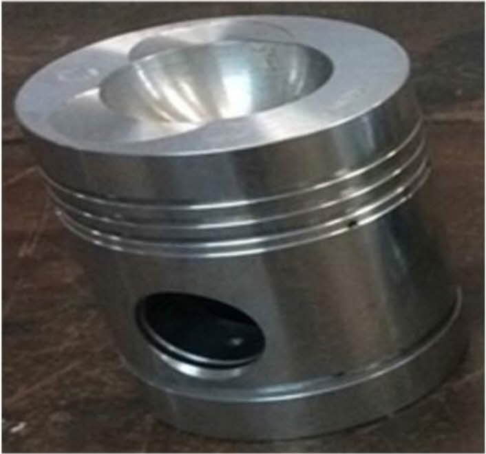
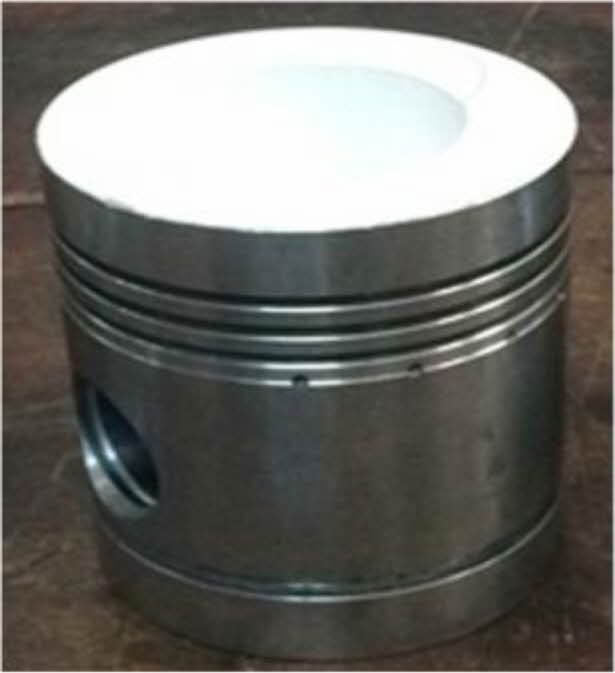
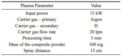
15 kW Plasma torch Ion Arc Tech, Coimbatore was used for processing of ML and NiCr spraying. ML powder is fed to plasma gun with Argon as carrier gas at 20 litre per minute, 15cm stand-off distance by using powder feeder – Metalizing Equip. Coimbatore. The test specimen were coated at plasma operating parameter (listed in Table 3) [27-28]. The images of the specimen before and after bilayered coatings is shown in Fig. 4 & 5.
Engine Setup and Measurements
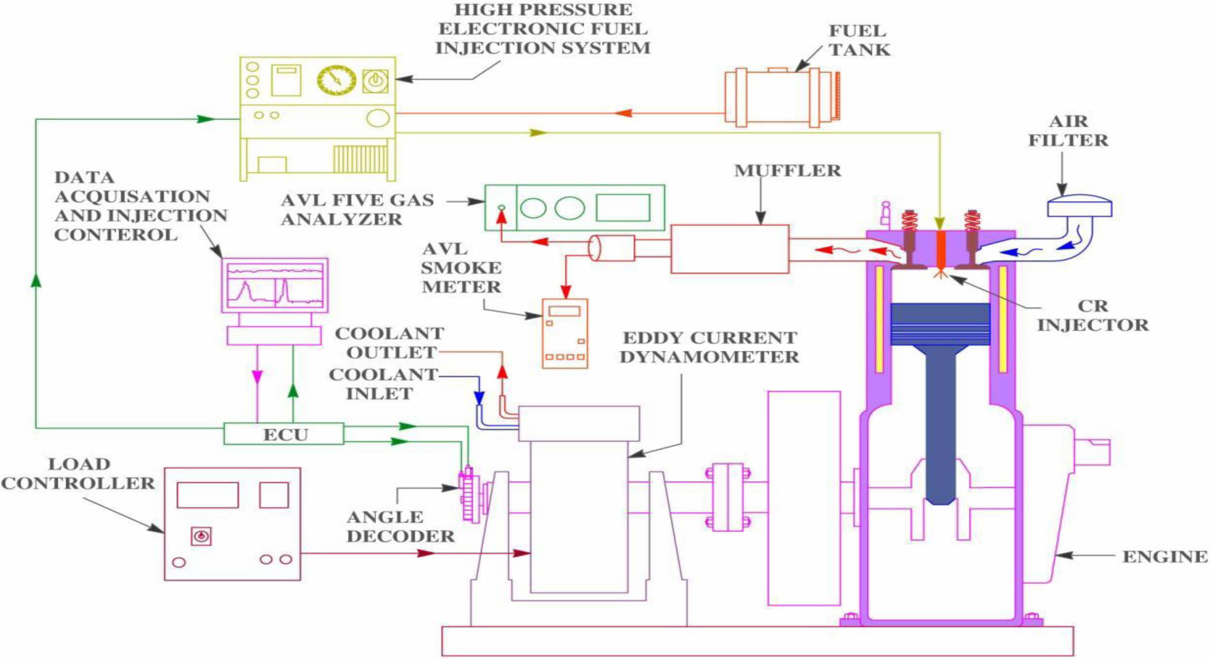
The performance and emission characteristics of the PJME test fuel with ML bilayered coated piston crown were done on Jeeto – 4 stroke, 9 HP, single cylinder, common rail injection diesel engine. The test setup and the accuracy of the gas analyser is shown in Fig. 6 and Table 4. The test setup was performed at pressure of 220 bar, 3000 rev/min. K-type thermocouple, AVL Di – gas analyser and Hartidge smoke tester were used for evaluation of exhaust gas temperature, HC / CO / NOx emission and smoke density values respectively. The equipment’s used in the test engine are : Eddy current dynamometer, Engine Control Unit – PE make, Data Acquisition Card – NI instruments, USA, Crank Angle – Kubber, Germany, Load Cell – VPG make, Cylinder Pressure – 350 bar, Air flow sensor – 0-250 mmWC and Fuel Flow Sensor (0-500 mm WC) – Yokogawa make.
Test Fuel
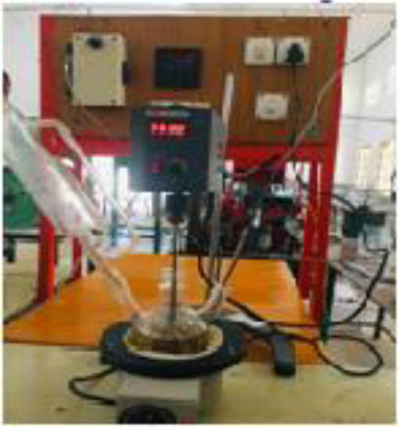
Prosopis Juliflora, a species of dicots belongs to flowering plants. The pulpy flat yellow fruits / pods of Prosopis Juliflora is of varying lengths from 60-300 mm and approximately yields upto 40kg/tree (shown in Fig. 1(a), 1(b) and 1(c)). Prosopis Juliflora is collected from the waste lands of Ramnathapuram district in Tamil Nadu. The dried pods after cleaning is powdered. Methanol as catalyst is mixed with alcohol in a stirrer at controlled pressure and temperature of 60 C. 100 ml of Prosopis Juliflora is mixed with this mixture and stirred for 60 minutes keeping other parameters as constant. Methyl Ester a by-product during trans-esterification of any edible / non-edible oils. Methyl Ester after 10 hrs. is separated after sedimentation. Reduction is the viscosity values as close as that of neat diesel was reported after two step process of washing with water keeping water: tannic acid at 20:1. Fig. 2 and Fig. 3 the schematic diagram to represent the preparation of test fuel. Acquired methyl ester is blended and used for performance evaluation in common rail direct injection (CRDI) diesel engines.
Preparation of F2O3 Nano Particles
Each litre of Methyl ester after extraction is doped with 0.025 g, 0.05 g, 0.075 g Fe2O3 Nano particles to make 25 ppm, 50 ppm and 75 ppm concentration levels. The mixture is stirred well in a homogenizer apparatus for 0.5 hrs. Nano particles is to be surface modified for steadiness. The presence of strong Van-der-Waals forces, preparation of homogeneous suspension will remain as a big challenge. Addition of surfactants or modification of surfaces to the particles has been reported to be the only possible solution. Mixture of Nano particles at 25 -75 ppm with C19H42NBr is weighed and is mixed with ethanol at 1% volumetric ratio. The mixture is stirred for 2 hrs inside a magnetic stirrer apparatus for formation of even Nano fluid.
Fuel Properties
The thermal and physical properties of the prepared test fuel blends were tested per ASTM standard (Table 1). Due to Higher molecular weight of the Nano blends, the density values were observed to be higher than the B25 fuel. Although, there was a dip in the calorific values; the flash and fire points of the Nano blends were significantly high. It is reported that the lower calorific values aids in the prospect of earlier combustion start.

|
Fig. 1 (a) Prosopis juliflora tree, (b) Prosopis juliflora pods, and (c) Prosopis juliflora seed. |
|
Fig. 2 Biodiesel extraction setup. |

|
Fig. 3 Preparation of fuel blend |
|
Fig. 4 Uncoated Piston |
|
Fig. 5 Mullite – 10% La2O3 – top coat and NiCr bond coated piston. |
|
Fig. 6 Engine Test Setup |
|
Table 2 Composition distribution model of MZ / ML composite processed using TAP |

FTIR of Fe2O3 nano particles
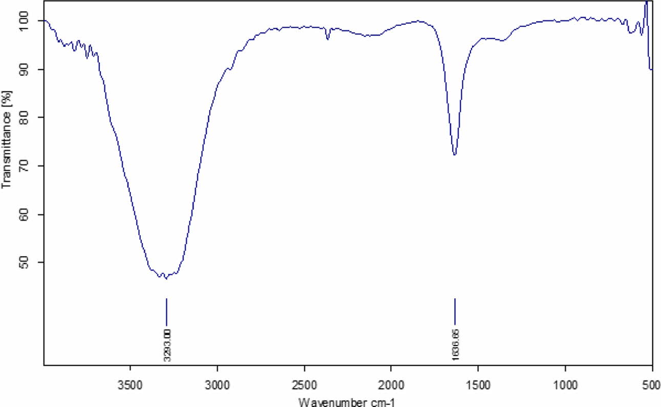
The crystalline nature of the nano powder is studied using FTIR study. The results of the study indicates that it is crystalline in nature (as shown in Fig. 7). It is observed to have higher frequency extending upto 735 cm-1 asymmetric absorption band at 589 cm-1. Also, it is observed to have peaks in the range 500 to 900 cm-1. The metal Fe-O bond of Fe2O3 is also evident at stretching vibration mode in two intense peaks at 584 cm-1 and 627 cm-1. In addition, C=O group is identified at 1636.65 cm-1 that is related to oleic acid molecule. The FTIR study reveals that the inverse spinel crystalline form endorsed the specific features of the spinel phase. Also, presene of certain subtances adsorbed in its surface.
Microstructure Characterization – SEM
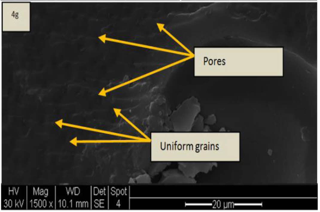
Scanning Electron Microscope – SEM images of the bilayered ML (top coat) and NiCr (bond coat) were studied using Philips XL40 make. As seen in SEM image (Fig. 8) the bilayered coatings surface has uniformly formed grains. As reported in literature, these uniformly formed grains in TBC improves the fracture toughness properties of the coatings [29-32]. The images also reflect that there is no crack on the bilayered coating surface. In Fig. 8, small pores holes are observed in the TBC coated surfaces; it is estimated to be due to the porosity increase in the plasma coated samples [22, 32, 33]. Also, the quick solidification of the edges and due to the release of trapped gases inside the coatings highly ropes to the pores formations are reported to be the reason [22].
Performance Characteristics - Brake thermal effi- ciency (BTE)
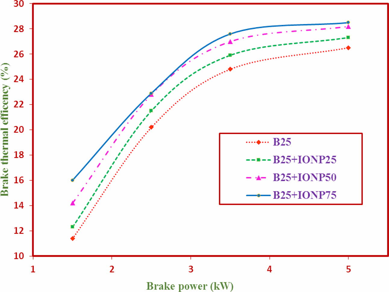
The results of the values of BTE of the coatings is represented in Fig. 9. The BTE values at maximum load condition for TF1, TF2, TF3 and TF4 are 24.62%, 24.73%, 24.71 and 24.96% respectively. The BTE values of the TF4 (B25+IONP75) is observed to have better BTE values when compared to other test fuels. This significant raise in the BTE values if due to higher combustion characteristics and maintenance of in chamber temperature [34]. It is also reported that, the nano particles added as a catalyst has greater surface area which contributes significantly to the chemical reaction [34]. From the experimental results, it is revealed that test fuel 4 has higher BTE performance values.
Emission Characteristics
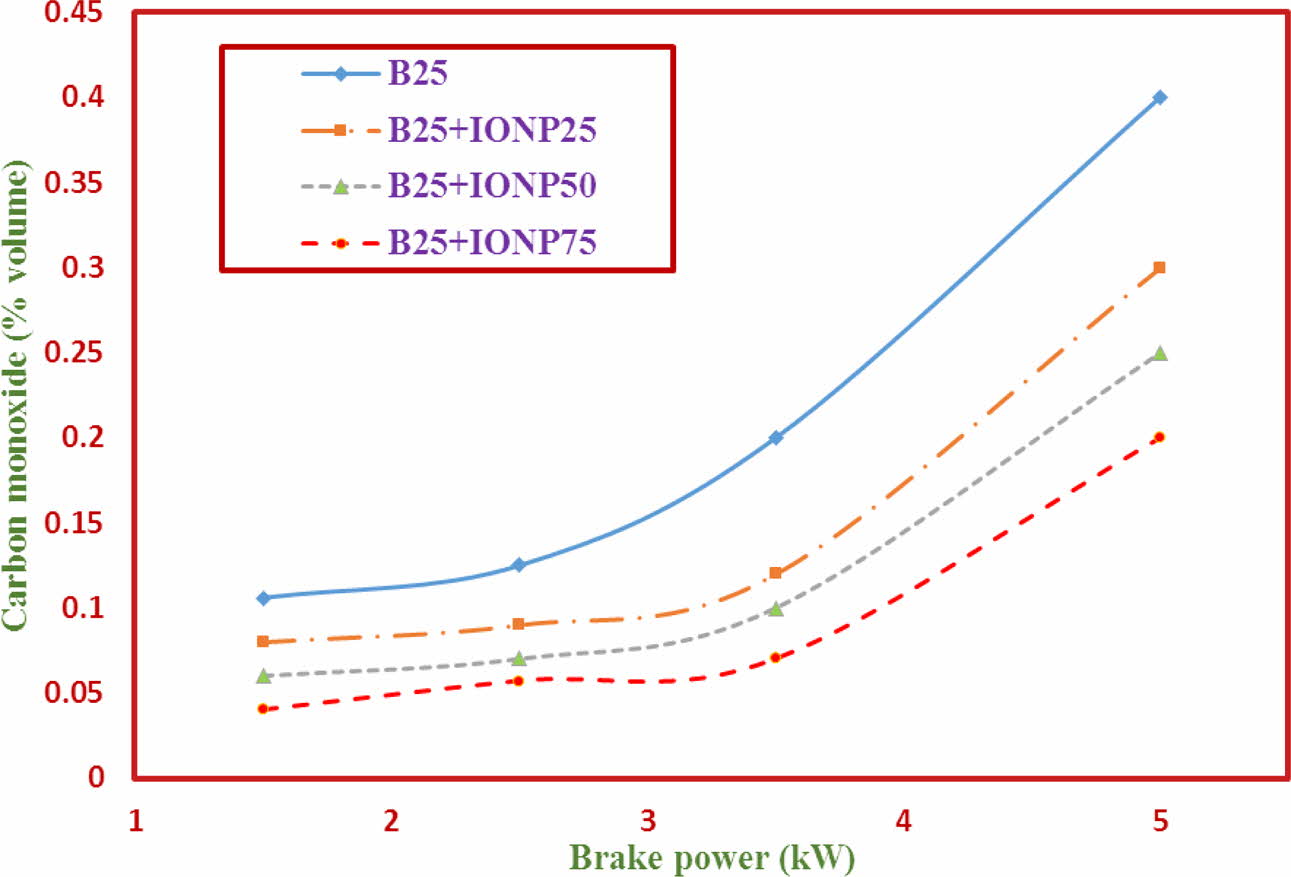
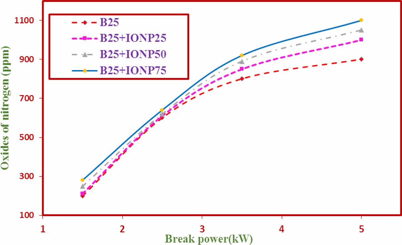
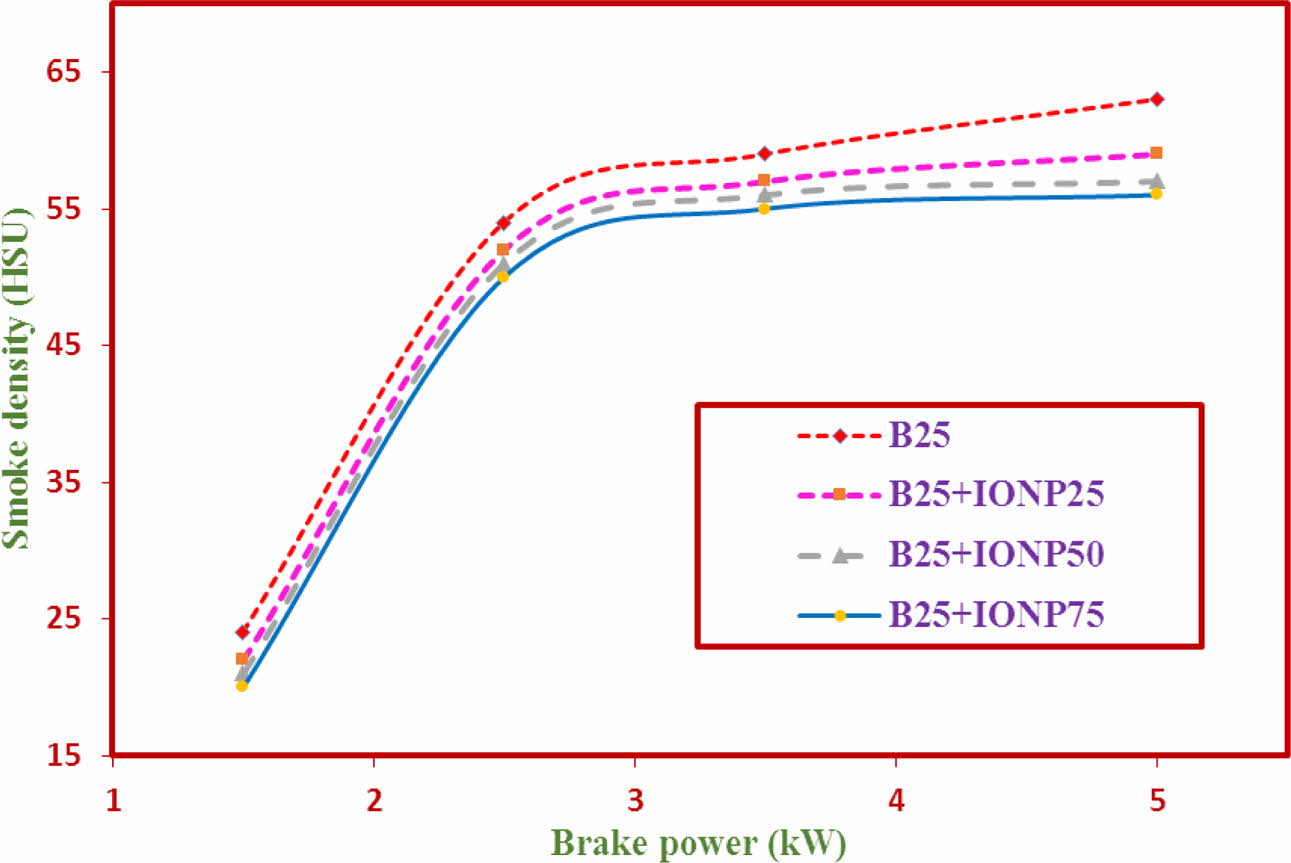
The results of the Hydro Carbon (HC), Carbon Monoxide (CO), NOx emission and smoke emission characteristics are represented in Figs. 10-13 respectively.
Hydrocarbon (HC)
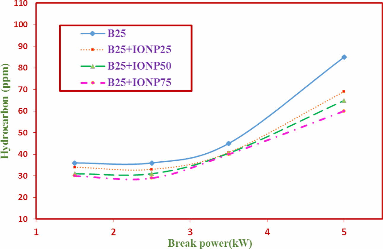
The variations of Hydro Carbon (HC) emission for TF1 to TF4 test fuels using bilayered coated piston crown is shown in Fig. 10. The results indicate that the HC emission levels with nano particles addition is reduced considerably. The emission values for TF1 to TF4 are 108 ppm, 100.2 ppm, 92.4 ppm and 83.8 ppm respectively. It is 22.4% reduction in HC emission values when TF1 fuel is compared with TF4 fuels. The results indicate that with the % increase in nano particle addition the oxygen level increases in the biodiesel blend. In addition, the maintenance of inchamber temperature due to ML bilayered coatings also reported to the reason.
Carbon Monoxide (CO)
The variations of Carbon Monoxide (CO) emission with brake power for TF1 to TF4 test fuels using bilayered coated piston crown is shown in Fig. 11. The results indicate that the CO emission levels with nano particles addition is reduced considerably. From the graph, it has been observed that the % reduction in CO emission values of TF2 – TF4 fuel with TF1 fuel are about 30%, 34% and 51.32% respectively. The nano particles blending acceelarates the combustion and reduces the ignition delay period. Due to this delay in ignition, the amount of fuel to O2 mixing is increased and aids in complete combustion of the fuel as reported in literature [36].
NOx Emissions
The variations of NOx emission for TF1 to TF4 test fuels using bilayered coated piston crown is shown in Fig. 12. From the graph, the results indicate that the NOx emission levels with nano particles addition is slightly increased for all test fuels. The NOx results for test fuels TF1 to TF4 were observed to be at 808ppm, 843ppm, 825 ppm and 884 ppm respectively. It is reported in literature that, the NOx values is affected by combustion temperature, local O2 concentration, and combustion time [28]. The % addition of nano particles invariably increases the % NOx emission values.
Smoke Emission
The results of smoke emission with brake power for TF1 to TF4 test fuels using bilayered coated piston crown at maximum load condition is shown in Fig. 13. The results indicate that the reduction in smoke density values for nano additive test fuels. The smoke emission values for test fuels TF1 to TF4 were observed to be at 78.7HSU, 66 HSU, 63HSU and 61.4 HSU respectively. The least of the smoke emission values were reflected at TF4 test fuel. The considerable amount of reduction in smoke emission was observerd at increasing % of Nano particles addition [36-47].
|
Fig. 7 FTIR spectrum of iron oxide nanoparticles |
|
Fig. 8 SEM image of ML coatings |
|
Fig. 9 Brake thermal efficiency against brake power. |
|
Fig. 10 HC Emission against brake power. |
|
Fig. 11 CO Emission against brake power. |
|
Fig. 12 NOx Emission against brake power. |
|
Fig. 13 Smoke emission against brake power. |
In this current work, Fe2O3 Nano particle blended with 25% PJME and Bilayered ML coatings in diesel engine were studied for its micro structure, performance, emission and combustion characteristics and the following conclusions were arrived:
• Bilayered ML coated piston crown coatings were intact even after endurance testing for 100 hrs.
• SEM image of the bilayered ML coatings surface has uniformly formed grains. BTE performance values improved for % increase in Nano particles addition from 25 ppm to 75 ppm and highest BTE value of 24% for test fuel 4.
• Calorific value and flash point values of test fuel with Nano particles were improved.
• Reduction in HC and CO Emission values as high as 26% and 48% respectively for test fuels with Nano particle additive (TF2 – TF3) when compared with test fuels without Nano particles addition (TF1) were observed.
• Slight increase in NOx emission values for test fuels with Nano particle additive (TF2 – TF3) when compared with test fuels without Nano particles addition (TF1) were observed
Based on the findings, it is concluded that Bilayered ceramic coatings with TF4 test fuel; the ppm values reduced by 23% for HC; CO emission reduced by 50%; reduced smoke emission values by 23% and augmented BTE values. The current research can be further extended to study the impact of the bilayered ceramic coatings on the mechanical properties.
- 1. P. Bridjesh, G. Rajendra Prasad. IJSRES. 1[4] (2014) 16-22.
- 2. X.Q. Cao, R. Vassen, D. Stöver. J. Eur. Ceram. Soc. 24 (2004) 1-10.
-

- 3. C. Aksel, Mater. Lett. 57 (2002) 708-714.
-

- 4. M. Matsumoto, N. Yamaguchi, H. Matsubara. Scripta. Materialia. 50 (2004) 867.
-

- 5. H. Lehmann, D. Pitzer, G. Pracht, R. Vassen, and D. Stover, J. Am. Ceram. Soc. 86 (2003) 1338.
-

- 6. M. Abbasa, L. Guoa, and H. Guo, Ceram. Int. 39 (2013) 5103-5111.
-

- 7. N.P. Bansal and D.M. Zhu, Surf. Coat. Tech. 202 (2008) 2698.
-

- 8. X.Q. Cao, Y.F. Zhang, J.F. Zhang, X.H. Zhong, Y. Wang H.M. Ma, Z.H. Xu, L.M. He, F. Lu, J. Eur. Ceram. Soc. 28 (2008) 1979.
-

- 9. H.B. Guo, H.J. Zhang, G.H. Ma and S.K. Gong, Surf. Coat. Tech. 204 (2009) 691.
-

- 10. C. Zanelli, M. Dondi, M. Raimondo and G. Guarini, J. Eur. Ceram. Soc. 30 (2010) 29-35.
-

- 11. P. Kumar, M. Nath, A. Ghosh and H.S. Tripathi, Materials Characterization, 101 (2015) 34-39.
-

- 12. R. Vassen, X. Cao, F. Tietz, D. Basu, and D. Stöver, J. Am. Ceram. Soc. 83[8] (2000) 2023-2028.
-

- 13. K.V. Kannan Nithin, N. Surriyanarayanan, and D.R. Antoneela Sola, J. Non-oxide Glasses 2 (2010) 23-34.
-

- 14. B. Shreeram, and I. Rajendran. J. Inorg. Organomet. P. 28[2] (2018) 2484-2493.
-

- 15. M.F. Bahbou, P. Nylen and J. Wigren, J. Therm. Spray. Techn. 13 (2003) 500-514.
-

- 16. Y. Li and K.A. Khor, Surf. Coat. Tech. 150[2-3] (2002) 125-132.
-

- 17. S.B. Weber, H.L. Lein, T. Grande, and M.A. Einarsrud, Surf. Coat. Tech. 227 (2013) 10-14.
-

- 18. Mustafa Balat, Energ. Convers. Manage. 52 (2011) 1479-1492.
-

- 19. M. Rajeshwaran, P. Ganeshan, K. Raja, J. Appl. Fluid. Mech. 11 (2018) 257-270.
-

- 20. A.E. Atabani, T.M.I. Mahlia, H.H. Masjuki, I.A. Badruddin, H.W. Yussof, W.T. Chong, and K.T. Lee, Energy, 58 (2013) 296-304.
-

- 21. H.J. Berchmans and S. Hirata, Bioresource. Technol. 99 (2008) 1716-1721.
-

- 22. D.F. Melvin Jose, R. Edwin Raj, B. Durga Prasad, Z. Robert Kennedy, and A. Mohammed Ibrahim, Appl. Energ., 88[6] (2011) 2056-2063.
-

- 23. M. Karabektas, G. Ergen, and M. Hosoz, Fuel 115 (2014) 855-860.
-

- 24. T. Shaafi, K. Sairam, A. Gopinath, G. Kumaresan, and R Velraj, Adv. Mater. Res-Switz. 49 (2015) 563-573.
-

- 25. C. Syed Aalam, C.G. Saravanan, M. Kannan, Alexandria Engineering Journal 54[3] (2015) 351-358.
-

- 26. B. Shreeram, I. Rajendran, and N. Pandiaraj, Int. J. Chem. Phys. Sci. 4 (2015) 20-28.
- 27. S. Yugeswaran, V. Selvarajan, M. Vijay, P.V. Ananthapadmanabhan, and K.P. Sreekumar, Ceram. Int. 2010; 36:141-149.
-

- 28. S. Bakthavathsalam, R.I. Gounder, and K. Muniappan. Environ. Sci. Pollut. R. 26 (2019) 24772-24794.
-

- 29. K.N. Pandiyaraj, R.R. Deshmukh, B.S. Ram, and R. Mahendiran, Nanosci. Nanotechnol. 2[1] (2014) 436-441.
- 30. M.M.S. Wahsh, R.M. Khattab, and M. Awaad, Adv. Mater. Res-Switz, 41 (2012) 31-36.
-

- 31. Masaki Yasuoka, Kiyoshi Hirao, Manuel E. Brito and Shuzo Kanzaki, J. Am. Ceram. Soc. 78[7] (1995) 1853-1856.
-

- 32. S. Yugeswaran, V. Selvarajan, P.V. Ananthapadmanabhan, and L. Lusvarghi. J. Phys. Conference Series 208 (2010) 012119.
-

- 33. W.J. Wang, Z.K. Fu, X. Cao, J. Guo, Q.Y. Liu, and M.H. Zhu, Tribol. Int. 94 (2016) 470-478.
-

- 34. H. Raheman and S.V. Ghadge, Fuel, 86[16] (2007) 2568-2573.
-

- 35. E. Buyukkaya, Fuel, 89[10] (2010) 3099-3105.
-

- 36. Remzi Gören, and Cem Özgür, J. Ceram. Process Res. 13[3] (2012) 262-266.
- 37. A.P. Senthil Kumar, S. Yuvaraj, and S. Janak, J. Ceram. Process Res. 21[2] (2020) 217-225
-

- 38. K. Suresh Kumar, K. Ganesan, and P.V. Subba Rao, Food Chemistry 107[1] (2008) 289-295.
-

- 39. C. Oner and S. Altun, Appl. Energy 86 (2009) 2114-2120.
-

- 40. M. Kannan, C.G. Saravanan, and S. Prasanna Raj Yadav, Int. J. Ambient Energy, 37 (2016) 354-362.
-

- 41. S. Lee, S.S. Choi, S. Li, J. Eastman. J. Heat. Transfer. 121[2] (1999) 280-289.
-

- 42. J.H. Lee, S.J. Lee, J.Y. Jeong, and S.J. Kim, J. Ceram. Process Res. 15[6] (2014) 519-524.
- 43. M. Chandrasekar, S. Suresh, A.C. Bose, Exp. Therm. Fluid. Sci. 34[2] (2010) 210-216.
-

- 44. M.M. Rashed, M.A. Kalam, H.H. Masjuki, M. Habibullah, H.K. Imdadul, M.M. Shahin, and M.M. Rahman, Ind. Crops. Prod. 89 (2016) 273-284.
-

- 45. H. Venu, V. Madhavan, J. Mech. Sci. Technol. 30[5] (2016) 2361-2368.
-

- 46. S. Baslayici, M. Bugdayci, and M.E. Acma, J. Ceram. Process Res. 22[1] (2021) 98-105.
-

- 47. W. Dong, Y. Liang, Q. Bao, X. Gu, and J. Yang, J. Ceram. Process Res. 22[3] (2021) 317-322.
-

 This Article
-
2022; 23(4): 459-465
Published on Aug 31, 2022
- 10.36410/jcpr.2022.23.4.459
- Received on Jan 12, 2022
- Revised on Feb 25, 2022
- Accepted on Feb 28, 2022
 Services
- Abstract
introduction
experimental work
materials and methods
results and discussion
conclusion
- References
- Full Text PDF
Shared
 Correspondence to
- M. Rajeshwaran
-
Mother Teresa College of Engineering and Technology, Illuppur, Pudukottai, India
Tel : +9442960598 - E-mail: biorajesh2011@gmail.com



 Copyright 2019 International Orgranization for Ceramic Processing. All rights reserved.